
Home ▸ STM32 Tutorials ▸ USB Tutorials ▸
Updated On: June 13, 2026
STM32 USB HID: Combine Mouse and Keyboard on One Port
This is Part 7 of the STM32 USB series. In the mouse and keyboard tutorial, we set up the STM32 as a mouse and as a keyboard, but as two separate projects.
In this post, we bring both together. The STM32 will act as a mouse and a keyboard at the same time, over a single USB connection. We will not use the Composite USB class this time. Instead, we will use one HID class and split the data using Report IDs.
If you have not gone through the mouse and keyboard tutorial yet, read that first. We will build directly on top of it, and we will reuse the working code from both projects.
You can follow the other parts of this series here:
- Part 1: STM32 USB CDC: Virtual COM Port
- Part 2: STM32 USB HID Gamepad
- Part 3: STM32 USB HID Mouse and Keyboard
- Part 4: STM32 USB MSC SD Card as External Drive
- Part 5: STM32 USB MSC with W25Q NOR Flash
- Part 6: STM32 USB Composite Device (CDC+HID)
How STM32 USB HID Mouse and Keyboard Combined Works
A single HID interface can carry more than one type of report. The trick is to add a Report ID as the first byte of every report. The host reads this byte first and knows whether the rest of the data belongs to the mouse or the keyboard.
This is different from the Composite class we used in Part 6. The Composite class creates two separate USB interfaces, one for each device. Here, we keep one interface and one endpoint, and we just tag each report with an ID.
Why Use Report IDs Instead of a Composite Class
A Composite device needs two interfaces, two endpoints, and extra descriptor work for the Interface Association Descriptor. That is more code and more places where things can go wrong.
With Report IDs, we only need one HID interface. We add a small 0x85 tag inside each descriptor block, and we add one extra byte at the start of each report buffer. The endpoint size is set to whichever report is bigger, so both reports fit through the same pipe.
This approach is simpler to set up, and it is the standard way most real devices, like gaming keyboards with built-in trackpads, handle multiple HID functions on one port.
Mouse Report With Report ID (5 Bytes)
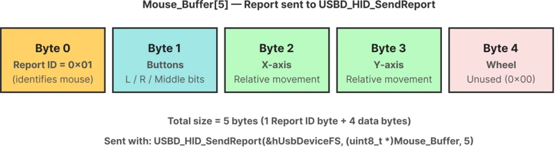
The plain mouse report was 4 bytes: button, X, Y, and wheel. Once we add the Report ID, it becomes 5 bytes. The Report ID always goes in byte 0, so every other byte shifts one position to the right.
| Byte | Content |
|---|---|
| 0 | Report ID = 0x01 |
| 1 | Button state |
| 2 | X-axis movement |
| 3 | Y-axis movement |
| 4 | Wheel (unused here) |
The image below shows the byte layout of the mouse report once the Report ID is added.
Keyboard Report With Report ID (9 Bytes)
The keyboard report was 8 bytes: modifier, reserved, and 6 key codes. With the Report ID added, it becomes 9 bytes.
| Byte | Content |
|---|---|
| 0 | Report ID = 0x02 |
| 1 | Modifier keys |
| 2 | Reserved (always 0x00) |
| 3–8 | Key codes (up to 6 keys) |
The image below shows the byte layout of the keyboard report once the Report ID is added.

Since the keyboard report (9 bytes) is bigger than the mouse report (5 bytes), we set the endpoint size to 9. The endpoint must be large enough for the biggest packet that passes through it.
STM32 Wiring for Mouse and Keyboard HID Project
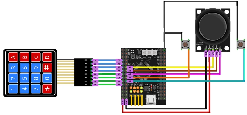
We are using the same parts as the earlier mouse and keyboard tutorial. The joystick handles mouse movement, two extra push buttons handle left and right click, and a 4×4 membrane keypad acts as the keyboard.
The image below shows the wiring diagram for the joystick and the two extra buttons, along with the Keyboard connected to the STM32.
Joystick and Buttons for the Mouse
The joystick gives us X and Y axis values through the ADC, and its own button works as the middle click.
| Signal | STM32 Pin | Function |
|---|---|---|
| Joystick X | PA1 | ADC1 Channel 1 |
| Joystick Y | PA3 | ADC1 Channel 3 |
| Joystick switch | PA5 | Middle click (input, pull-up) |
| Left click button | PA7 | Left click (input, pull-up) |
| Right click button | PC5 | Right click (input, pull-up) |
The joystick runs on the 3.3V supply from the development board. Both extra buttons connect to ground on one side, so pressing a button pulls the pin low.
4×4 Keypad Wiring for the Keyboard
The keypad has 4 row pins and 4 column pins. Rows are outputs, columns are inputs.
| Keypad Pin | STM32 Pin | Mode |
|---|---|---|
| Row 1 (R1) | PB2 | Output |
| Row 2 (R2) | PB0 | Output |
| Row 3 (R3) | PC4 | Output |
| Row 4 (R4) | PA6 | Output |
| Col 1 (C1) | PA4 | Input |
| Col 2 (C2) | PA2 | Input |
| Col 3 (C3) | PA0 | Input |
| Col 4 (C4) | PC2 | Input |
All column pins use pull-up resistors. Row pins stay high by default, and we pull one of them low at a time inside the code to scan the keypad.
STM32CubeMX Setup for Combined HID Mouse and Keyboard
We will start the project from scratch in CubeMX, configure the ADC, GPIO pins, and USB, then move on to the code changes in usbd_hid.c and main.c.
HID and Clock Configuration
Once the USB peripheral is enabled, go to the Middleware section. Under USB Device, select the HID class (not Custom HID).

Under HID Parameters, there is one setting worth noting: HID_FS_BINTERVAL. This is set to 0x0A by default, which means the USB host will poll the device for new data every 10 milliseconds. That is perfectly adequate for a mouse and Keyboard. We will keep it as is.
Next we need to make sure the USB peripheral receives exactly 48 MHz, so go into the clock tree and adjust the PLL multipliers and dividers accordingly.

We will first test our basic driver, so this configuration is enough. When this works fine, we will configure the ADC and button in CubeMX.
ADC, DMA and Button Configuration for the Mouse
Now we add the actual joystick and the rest of the buttons for the mouse.
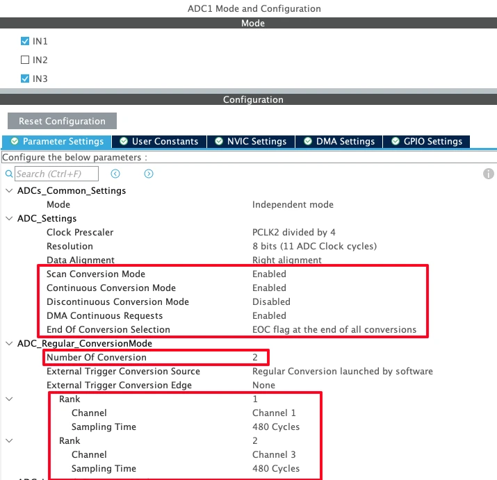
Enable ADC1 with Channel 1 (PA1, X axis) and Channel 3 (PA3, Y axis).
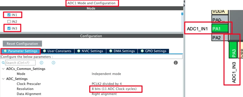
Set the resolution to 8 bits — this matches our descriptor, which expects 8bit data.
Note:
If you are using an STM32F103 (Blue Pill), ADC resolution is fixed at 12 bits. In that case, keep it at 12 bits but map the 0–4095 range down to 0–255 in code before filling the HID buffer.
Under DMA Settings, add a DMA request for ADC1. Set the mode to Circular and the data width to Byte (since we are using 8-bit resolution).

Back in the Parameter Settings, make the following changes:
- Increase the Clock Prescaler — this slows down the conversions so DMA transfers do not interfere with the HID send loop.
- Set Number of Conversions to 2.
- Enable Scan Conversion Mode (auto-enabled when you set 2 conversions).
- Enable Continuous Conversion Mode.
- Enable DMA Continuous Requests.
- Set End of Conversion Selection to End of All Conversions — this way the DMA interrupt only fires after both channels are done, not after each individual conversion.
Under the Rank configuration, set Rank 1 to Channel 1 (X axis) and Rank 2 to Channel 3 (Y axis). Increase the Sampling Time for both ranks to keep the conversion rate manageable.
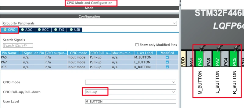
Now configure the buttons. Set PA5, PA7 and PC5 as GPIO Inputs. In the GPIO settings, enable the internal Pull-up resistor for these pins.
Reminder:
If CubeMX regenerates the project, it will overwrite usbd_hid.c. Copy the descriptor before regenerating and paste it back after. Also re-apply the HID_MOUSE_REPORT_DESC_SIZE and HID_EPIN_SIZE changes in usbd_hid.h.
GPIO Configuration for the Keyboard (Keypad)
Now we will add the pins for the keyboard. We will configure 8 pins (4 Outputs for the Rows and 4 Inputs for the Columns).
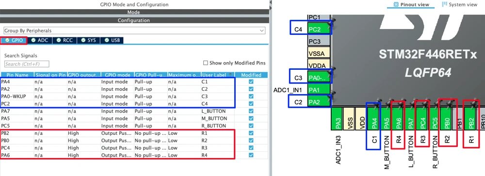
Set the following pins as GPIO Output and label them R1–R4:
- PB2 → R1
- PB0 → R2
- PC4 → R3
- PA6 → R4
Set the following pins as GPIO Input and label them C1–C4:
- PA4 → C1
- PA2 → C2
- PA0 → C3
- PC2 → C4
Go to GPIO Configuration. Select all four column pins, enable the Pull-up resistor for each one.
STM32 HID Code: Descriptors and main.c for Mouse and Keyboard
Updating the HID Descriptors with Report IDs
Open the generated project in STM32CubeIDE and go to Middlewares > ST > STM32_USB_Device_Library > Class > HID > Src > usbd_hid.c. CubeMX generates the mouse descriptor here by default.
Add the Keyboard Descriptors below the mouse descriptor inside the same array in usbd_hid.c. The mouse descriptor array was closed before, so add a comma after its last entry to join both blocks together.
__ALIGN_BEGIN static uint8_t HID_MOUSE_ReportDesc[HID_MOUSE_REPORT_DESC_SIZE] __ALIGN_END =
{
  // Mouse Descriptors
  0x05, 0x01,        /* Usage Page (Generic Desktop Ctrls)     */
  0x09, 0x02,        /* Usage (Mouse)                          */
  0xA1, 0x01,        /* Collection (Application)               */
  0x85, 0x01,        /* Report ID = 1                          */ ← Add this Report ID
  0x09, 0x01,        /*   Usage (Pointer)                      */
  0xA1, 0x00,        /*   Collection (Physical)                */
  0x05, 0x09,        /*     Usage Page (Button)                */
  0x19, 0x01,        /*     Usage Minimum (0x01)               */
  0x29, 0x03,        /*     Usage Maximum (0x03)               */
  0x15, 0x00,        /*     Logical Minimum (0)                */
  0x25, 0x01,        /*     Logical Maximum (1)                */
  0x95, 0x03,        /*     Report Count (3)                   */
  0x75, 0x01,        /*     Report Size (1)                    */
  0x81, 0x02,        /*     Input (Data,Var,Abs)               */
  0x95, 0x01,        /*     Report Count (1)                   */
  0x75, 0x05,        /*     Report Size (5)                    */
  0x81, 0x01,        /*     Input (Const,Array,Abs)            */
  0x05, 0x01,        /*     Usage Page (Generic Desktop Ctrls) */
  0x09, 0x30,        /*     Usage (X)                          */
  0x09, 0x31,        /*     Usage (Y)                          */
  0x09, 0x38,        /*     Usage (Wheel)                      */
  0x15, 0x81,        /*     Logical Minimum (-127)             */
  0x25, 0x7F,        /*     Logical Maximum (127)              */
  0x75, 0x08,        /*     Report Size (8)                    */
  0x95, 0x03,        /*     Report Count (3)                   */
  0x81, 0x06,        /*     Input (Data,Var,Rel)               */
  0xC0,              /*   End Collection                       */
  0x09, 0x3C,        /*   Usage (Motion Wakeup)                */
  0x05, 0xFF,        /*   Usage Page (Reserved 0xFF)           */
  0x09, 0x01,        /*   Usage (0x01)                         */
  0x15, 0x00,        /*   Logical Minimum (0)                  */
  0x25, 0x01,        /*   Logical Maximum (1)                  */
  0x75, 0x01,        /*   Report Size (1)                      */
  0x95, 0x02,        /*   Report Count (2)                     */
  0xB1, 0x22,        /*   Feature (Data,Var,Abs,NoWrp)         */
  0x75, 0x06,        /*   Report Size (6)                      */
  0x95, 0x01,        /*   Report Count (1)                     */
  0xB1, 0x01,        /*   Feature (Const,Array,Abs,NoWrp)      */
  0xC0,              /* End Collection                         */

  // Keyboard Descriptors
  0x05, 0x01,        /* Usage Page (Generic Desktop Ctrls)     */
  0x09, 0x06,        /* Usage (Keyboard)                       */
  0xA1, 0x01,        /* Collection (Application)               */
  0x85, 0x02,        /* Report ID = 2                          */ ← Add this Report ID
  0x05, 0x07,        /*   Usage Page (Keyboard)                */
  0x19, 0xE0,        /*   Usage Minimum (0xE0)                 */
  0x29, 0xE7,        /*   Usage Maximum (0xE7)                 */
  0x15, 0x00,        /*   Logical Minimum (0)                  */
  0x25, 0x01,        /*   Logical Maximum (1)                  */
  0x95, 0x08,        /*   Report Count (8)                     */
  0x75, 0x01,        /*   Report Size (1)                      */
  0x81, 0x02,        /*   Input (Data,Var,Abs)                 */
  0x95, 0x01,        /*   Report Count (1)                     */
  0x75, 0x08,        /*   Report Size (8)                      */
  0x81, 0x01,        /*   Input (Const,Array,Abs)              */
  0x19, 0x00,        /*   Usage Minimum (0x00)                 */
  0x29, 0x65,        /*   Usage Maximum (0x65)                 */
  0x15, 0x00,        /*   Logical Minimum (0)                  */
  0x25, 0x65,        /*   Logical Maximum (0x65)               */
  0x75, 0x08,        /*   Report Size (8)                      */
  0x95, 0x06,        /*   Report Count (6)                     */
  0x81, 0x00,        /*   Input (Data,Array,Abs)               */
  0xC0,              /*   End Collection                       */
};Along with keyboard descriptors, also add the Report IDs. Inside the mouse descriptor, right after the collection opens (0xA1, 0x01), insert:
0x85, 0x01, /* Report ID = 1 (Mouse) */Inside the keyboard descriptor, right after its collection opens, insert:
0x85, 0x02, /* Report ID = 2 (Keyboard) */These two bytes tell the host which report type follows.
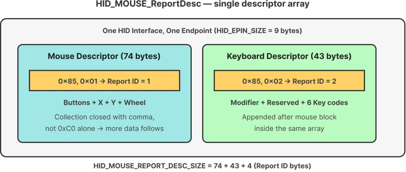
The image below shows how the two descriptor blocks sit inside one array, each with its own Report ID.
Here is the full combined descriptor array, as it should look in usbd_hid.c:
Now update usbd_hid.h. The mouse descriptor alone was 74 bytes. The keyboard descriptor is 43 bytes. We added 4 extra bytes total for the two Report ID fields (2 bytes each). So the new descriptor size is:
#define HID_MOUSE_REPORT_DESC_SIZE (74U + 43U + 4U)For the endpoint size, the mouse now needs 5 bytes (4 data bytes + Report ID) and the keyboard needs 9 bytes (8 data bytes + Report ID). The endpoint size must fit the larger of the two:
#define HID_EPIN_SIZE 0x09UMouse Buffer and ADC Callback in main.c
The mouse buffer grows from 4 bytes to 5 bytes. Byte 0 holds the Report ID, byte 1 holds the button state, byte 2 holds X movement, and byte 3 holds Y movement.
int8_t Mouse_Buffer[5] = {0};
uint8_t ADC_Val[2];

void HAL_ADC_ConvCpltCallback(ADC_HandleTypeDef *hadc)
{
    if      (ADC_Val[0] > 200) Mouse_Buffer[2] =  10;
    else if (ADC_Val[0] <  55) Mouse_Buffer[2] = -10;
    else                       Mouse_Buffer[2] =  0;

    if      (ADC_Val[1] > 200) Mouse_Buffer[3] =  10;
    else if (ADC_Val[1] <  55) Mouse_Buffer[3] = -10;
    else                       Mouse_Buffer[3] =  0;
}Notice that X and Y now go into bytes 2 and 3, not bytes 1 and 2 as before. Every field shifted right by one place to make room for the Report ID.
Keyboard Buffer and Keypad Scan
The keyboard buffer grows from 8 bytes to 9 bytes. Byte 0 holds the Report ID, byte 1 holds the modifier, byte 2 stays reserved, and byte 3 holds the key code.
uint8_t Keyboard_Buffer[9] = {0};
uint8_t modifier = 0;
uint8_t keycode = 0;

void scanKeypad(void)
{
    modifier = keycode = 0;

    HAL_GPIO_WritePin(R1_GPIO_Port, R1_Pin, GPIO_PIN_RESET);
    HAL_GPIO_WritePin(R2_GPIO_Port, R2_Pin, GPIO_PIN_SET);
    HAL_GPIO_WritePin(R3_GPIO_Port, R3_Pin, GPIO_PIN_SET);
    HAL_GPIO_WritePin(R4_GPIO_Port, R4_Pin, GPIO_PIN_SET);
    HAL_Delay(1);
    if (HAL_GPIO_ReadPin(C1_GPIO_Port, C1_Pin) == GPIO_PIN_RESET) keycode = 0x1E;  // 1
    if (HAL_GPIO_ReadPin(C2_GPIO_Port, C2_Pin) == GPIO_PIN_RESET) keycode = 0x1F;  // 2
    if (HAL_GPIO_ReadPin(C3_GPIO_Port, C3_Pin) == GPIO_PIN_RESET) keycode = 0x20;  // 3
    if (HAL_GPIO_ReadPin(C4_GPIO_Port, C4_Pin) == GPIO_PIN_RESET) keycode = 0x04;  // a

    HAL_GPIO_WritePin(R1_GPIO_Port, R1_Pin, GPIO_PIN_SET);
    HAL_GPIO_WritePin(R2_GPIO_Port, R2_Pin, GPIO_PIN_RESET);
    HAL_GPIO_WritePin(R3_GPIO_Port, R3_Pin, GPIO_PIN_SET);
    HAL_GPIO_WritePin(R4_GPIO_Port, R4_Pin, GPIO_PIN_SET);
    HAL_Delay(1);
    if (HAL_GPIO_ReadPin(C1_GPIO_Port, C1_Pin) == GPIO_PIN_RESET) keycode = 0x21;  // 4
    if (HAL_GPIO_ReadPin(C2_GPIO_Port, C2_Pin) == GPIO_PIN_RESET) keycode = 0x22;  // 5
    if (HAL_GPIO_ReadPin(C3_GPIO_Port, C3_Pin) == GPIO_PIN_RESET) keycode = 0x23;  // 6
    if (HAL_GPIO_ReadPin(C4_GPIO_Port, C4_Pin) == GPIO_PIN_RESET) keycode = 0x05;  // b

    HAL_GPIO_WritePin(R1_GPIO_Port, R1_Pin, GPIO_PIN_SET);
    HAL_GPIO_WritePin(R2_GPIO_Port, R2_Pin, GPIO_PIN_SET);
    HAL_GPIO_WritePin(R3_GPIO_Port, R3_Pin, GPIO_PIN_RESET);
    HAL_GPIO_WritePin(R4_GPIO_Port, R4_Pin, GPIO_PIN_SET);
    HAL_Delay(1);
    if (HAL_GPIO_ReadPin(C1_GPIO_Port, C1_Pin) == GPIO_PIN_RESET) keycode = 0x24;  // 7
    if (HAL_GPIO_ReadPin(C2_GPIO_Port, C2_Pin) == GPIO_PIN_RESET) keycode = 0x25;  // 8
    if (HAL_GPIO_ReadPin(C3_GPIO_Port, C3_Pin) == GPIO_PIN_RESET) keycode = 0x26;  // 9
    if (HAL_GPIO_ReadPin(C4_GPIO_Port, C4_Pin) == GPIO_PIN_RESET) keycode = 0x06;  // c

    HAL_GPIO_WritePin(R1_GPIO_Port, R1_Pin, GPIO_PIN_SET);
    HAL_GPIO_WritePin(R2_GPIO_Port, R2_Pin, GPIO_PIN_SET);
    HAL_GPIO_WritePin(R3_GPIO_Port, R3_Pin, GPIO_PIN_SET);
    HAL_GPIO_WritePin(R4_GPIO_Port, R4_Pin, GPIO_PIN_RESET);
    HAL_Delay(1);
    if (HAL_GPIO_ReadPin(C1_GPIO_Port, C1_Pin) == GPIO_PIN_RESET) modifier |= 1<<1;  // L-SHIFT
    if (HAL_GPIO_ReadPin(C2_GPIO_Port, C2_Pin) == GPIO_PIN_RESET) keycode = 0x2C;    // 0  SPACE
    if (HAL_GPIO_ReadPin(C3_GPIO_Port, C3_Pin) == GPIO_PIN_RESET) keycode = 0x2A;    // BACKSPACE
    if (HAL_GPIO_ReadPin(C4_GPIO_Port, C4_Pin) == GPIO_PIN_RESET) keycode = 0x07;    // d
}The scanKeypad function itself does not change. It still scans the rows one at a time and stores the result in modifier and keycode. We just place the result into byte 1 and byte 3 of Keyboard_Buffer instead of byte 0 and byte 2.
The Main Loop
The main loop now sends two reports — one for the mouse and one for the keyboard. Both buffers are sent through the same USBD_HID_SendReport function, but with different sizes and different Report IDs.
while (1)
{
    Mouse_Buffer[0] = 0x01;  // Report ID = 1 for Mouse

    if (HAL_GPIO_ReadPin(L_BUTTON_GPIO_Port, L_BUTTON_Pin) == 0)
        Mouse_Buffer[1] = 0x01;

    if (HAL_GPIO_ReadPin(R_BUTTON_GPIO_Port, R_BUTTON_Pin) == 0)
        Mouse_Buffer[1] = 0x02;

    if (HAL_GPIO_ReadPin(M_BUTTON_GPIO_Port, M_BUTTON_Pin) == 0)
        Mouse_Buffer[1] = 0x04;

    USBD_HID_SendReport(&hUsbDeviceFS, (uint8_t *)Mouse_Buffer, 5);
    Mouse_Buffer[1] = 0;
    HAL_Delay(5);

    scanKeypad();
    Keyboard_Buffer[0] = 0x02;  // Report ID = 2 for Keyboard
    Keyboard_Buffer[1] = modifier;
    Keyboard_Buffer[3] = keycode;

    USBD_HID_SendReport(&hUsbDeviceFS, (uint8_t *)Keyboard_Buffer, 9);
    HAL_Delay(5);
}Output
The GIF below shows the STM32 board connected to the PC, with the joystick controlling the mouse cursor and the keypad typing characters at the same time.

STM32 USB HID: Mouse and Keyboard Combined — Video Tutorial
This video shows how to combine a USB mouse and keyboard into a single STM32 HID device using one HID class and Report IDs. We configure the joystick and buttons for the mouse, a 4×4 keypad for the keyboard, update the HID descriptors, and test both devices working together over one USB connection.
STM32 USB HID Mouse and Keyboard — FAQs
Conclusion
We combined the mouse and the keyboard into a single USB HID device, without using the Composite class. By adding a Report ID byte to each descriptor and each data buffer, the host can tell the two reports apart and treat the STM32 as both a mouse and a keyboard at the same time.
The mouse project showed how the buffer layout shifts once a Report ID is added, and the keyboard project showed the same shift for its own buffer. We also saw why the endpoint size has to match the larger of the two reports, and why the send delay matters once two reports share the same loop.
This setup is a solid base for adding more HID functions later, such as a custom control panel or a media key set.
Download STM32 USB HID Mouse and Keyboard Combined Project
Complete STM32CubeMX project and HAL source code showing a single HID interface that carries both mouse and keyboard reports using Report IDs. Free to use — support the work if it helped you.
Browse More STM32 USB Tutorials
STM32 USB HID Gamepad: Configure STM32 as a Game Controller
STM32 as USB Mouse and Keyboard — HID Device Implementation

STM32 USB Mass Storage Class: Use SD Card as External Drive

STM32 USB Mass Storage Class with W25Q NOR Flash: External Drive over SPI

STM32 USB Composite Class: CDC + HID Gamepad on One USB Port

Subscribe
Login
0 Comments
Newest
