Home ▸ STM32 Tutorials ▸ USB Tutorials ▸
Updated On: July 11, 2026
STM32 USB Mass Storage Class: Use W25Q NOR Flash as an External Drive
This is Part 5 of the STM32 USB series. In Part 4, we used the USB Mass Storage Class with an SD card connected over SDIO, and the SD card appeared as a removable drive on the computer. This time, we are going to do the same thing, but with a W25Q SPI NOR Flash module instead.
The Mass Storage Class does not care what kind of storage is behind it. As long as we implement the read, write, and capacity functions correctly, the host computer treats it as an external drive. So in this tutorial, we swap the SD card out and bring in the W25Q Flash module connected over SPI.
In this tutorial, we will configure SPI1, integrate the W25Q library, test the Flash memory independently, and then implement the usbd_storage_if.c functions to expose it as a USB drive.
You can follow the other parts of this series here:
- Part 1: STM32 USB CDC — Virtual COM Port
- Part 2: STM32 USB HID Gamepad
- Part 3: STM32 USB HID Mouse and Keyboard
- Part 4: STM32 USB MSC SD Card as External Drive
- Part 6: STM32 USB Composite Device (CDC + HID)
- Part 7: STM32 USB HID Mouse and Keyboard Combined
- Part 8: STM32 USB Host MSC: Read & Write USB Flash Drive
- Part 9: STM32 USB HOST HID: Interface Mouse and Keyboard with STM32
- Part10: STM32 USB Host Audio Class
- Part11: STM32 USB DFU Bootloader
How W25Q Flash Works with USB MSC
Before writing any code, it helps to understand the two key pieces involved here — the W25Q Flash memory and how the USB Mass Storage Class sits on top of it.
W25Q NOR Flash Memory
The W25Q series from Winbond is a family of SPI NOR Flash chips. They come in different sizes of 8 Mbit, 16 Mbit, 32 Mbit, and so on. The W25Q16JV used in this project is 16 Mbit, which is 2 MB.
There are a few things about NOR Flash that are important to understand before using it as a storage medium:
- Page size is 256 bytes. You can only write up to 256 bytes at a time. Writing more than that in a single operation causes the data to wrap around and overwrite from the beginning of the same page.
- Sector size is 4 KB. Before writing, you must erase the sector first. Flash memory cannot overwrite existing data. It can only change bits from 1 to 0, and erase resets everything back to 1.
- It is non-volatile. Data is retained even after power is removed, unlike RAM.
The USB Mass Storage Class Bridge
The USB Mass Storage Class (MSC) makes the STM32 appear to the host as a block storage device. The host sends standard SCSI commands like “what is your capacity”, “read block 50”, or “write block 100”. The STM32 translates those into actual read/write operations on the W25Q Flash.
CubeMX generates a file called usbd_storage_if.c. This file is the bridge between the USB stack and the storage. It has six functions we need to implement:
| Function | Purpose |
|---|---|
STORAGE_Init_FS | Initialize the storage medium |
STORAGE_GetCapacity_FS | Report block count and block size |
STORAGE_IsReady_FS | Check if storage is ready |
STORAGE_IsWriteProtected_FS | Tell the host if writes are allowed |
STORAGE_Read_FS | Read one or more blocks |
STORAGE_Write_FS | Write one or more blocks |
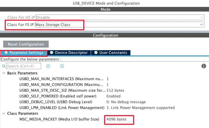
Why Block Size is 4096 Bytes Here
In the previous project with the SD card, we used a block size of 512 bytes, because that is the native sector size of SD cards. For the W25Q Flash, the native sector size is 4096 bytes (4 KB). We configure the media packet size in CubeMX to match this, so the host reads or writes exactly one sector at a time. This also means we only need one erase operation per write cycle, which simplifies the write function significantly.
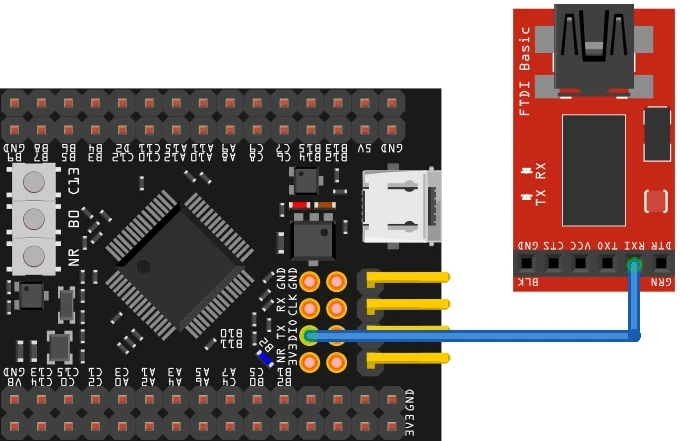
Wiring and Connections
The W25Q Flash module connects to the STM32 over SPI. We also have a USB-to-TTL module for serial logging. Here is the full connection summary.
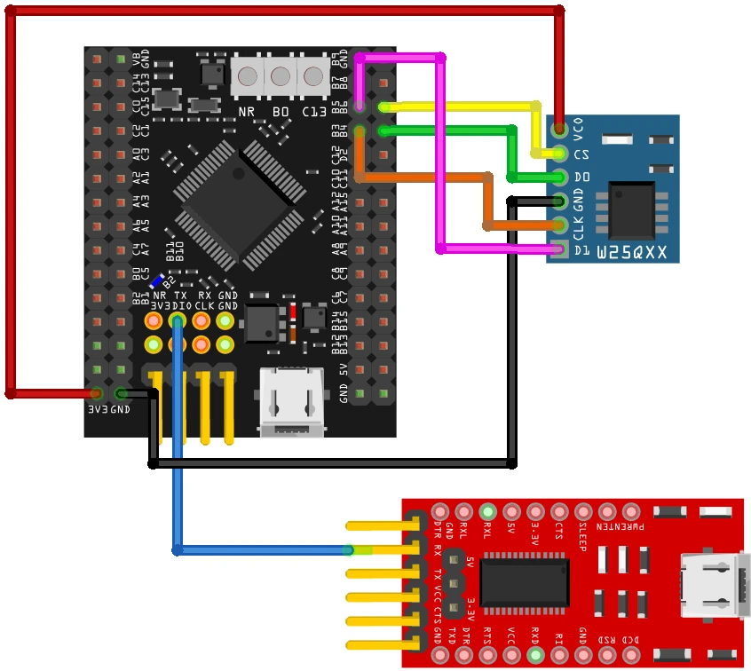
| W25Q Pin | STM32 Pin | Function |
|---|---|---|
| CLK | PB3 | SPI1 Clock |
| DO (Data Out) | PB4 | SPI1 MISO |
| DI (Data In) | PB5 | SPI1 MOSI |
| CS | PB6 | GPIO Output (Chip Select) |
| VCC | 3.3V | Power |
| GND | GND | Ground |
The USB data lines (PA11 and PA12) are assigned automatically by CubeMX when USB OTG FS is enabled. The USB-to-TTL module connects to the USART1 TX pin for serial log output.
CubeMX Setup for USB MSC and SPI
Let’s go through the full CubeMX configuration for this project.
USB Peripheral Configuration
The first thing we need to do is enable the USB peripheral. Locate and enable the USB Device (FS) or USB OTG FS peripheral, depending on your board. Make sure to choose Device Only mode, since we are using STM32 as a USB device connected to a PC. Once you do this, CubeMX automatically assigns PA11 and PA12 as the USB D− and D+ lines.

Note that all the parameters, low power mode, VBUS sensing, SOF output are disabled for a basic setup. We are using USB FS, this runs at Full Speed (12 Mbit/s).
Now go to the Middleware section and set the USB Device class to Mass Storage Class (MSC). Under the MSC parameters, set the media packet buffer size to 4096.
A few parameters worth noting:
- Max number of configurations: Keep this at 1. Multiple configurations are used in composite device scenarios.
- Max number of interfaces: Keep this at 1 for now. In later tutorials we will add composite interfaces.
- USB self-powered: Set to enabled, since the board has its own power supply and does not draw operating power from the USB bus.
Clock Configuration
Next, we need to configure the clock. Enable the external high-speed oscillator (HSE) using the onboard 8 MHz crystal, and use the PLL to scale the system clock up to 180 MHz. We also need to make sure the USB peripheral receives exactly 48 MHz, so adjust the PLL multipliers and dividers accordingly.

UART Configuration
Enable UART1 in asynchronous mode with default settings. We will use this for logging via a USB-to-TTL adapter. The TX pin is PA9 and the RX pin is PA10.
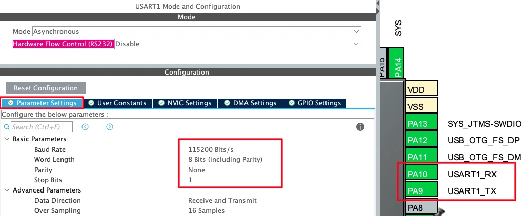
Connect the STM32 TX pin to the RX pin of your USB-to-TTL module.
SPI Peripheral Configuration
Enable SPI1 in Full-Duplex Master mode. By default, CubeMX assigns PA5, PA6, and PA7 as the SPI1 pins. We need to remap them to PB3, PB4, and PB5 to match the connection diagram.
- PB3 → SPI1_SCK (Clock)
- PB4 → SPI1_MISO (Data Out from module)
- PB5 → SPI1_MOSI (Data In to module)
- PB6 → GPIO_Output, user label:
CS
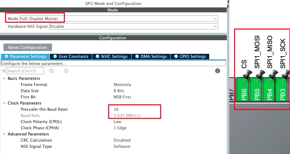
In the SPI1 parameter settings, configure the following:
- Data Size: 8 bits
- First Bit: MSB First
- Prescaler: set so the baud rate is approximately 5 Mbit/s (can be increased if needed)
- Clock Polarity (CPOL): Low
- Clock Phase (CPHA): 1 Edge
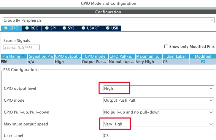
GPIO Configuration
In the GPIO settings for PB6, set the default output level to High. This keeps the Chip Select line Unselected when the program starts. Also set the output speed to Very High, as the CS pin needs to toggle quickly during SPI transfers.
W25Q Library Setup and Testing
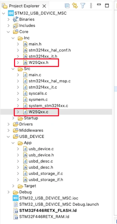
The W25Q library is included in the downloadable project. Copy W25Qxx.c into the Core/Src directory and W25Qxx.h into the Core/Inc directory.
The header file defines the page size (256 bytes) and sector size (4096 bytes). These are the same across all W25Q chips, so no changes are needed there.
The source file has two definitions to check:
#define W25Q_CHIP_SIZE   16     // Size in Megabits — change this for your chip
#define W25Q_SPI hspi1 // SPI instance — change if using SPI2 or SPI3For the W25Q16JV used here, the chip size is 16. If you are using a different chip, set this to the correct megabit value. The rest of the library calculations depend on this.
The library provides four functions we will use throughout this project:
| Function | Description |
|---|---|
W25Q_ReadID() | Returns the manufacturer and device ID |
W25Q_EraseSector(sector) | Erases the specified sector (4 KB) |
W25Q_ReadBytes(addr, buf, len) | Reads len bytes starting from addr |
W25Q_WriteBytes(addr, buf, len) | Writes up to 256 bytes starting from addr |
Setting up Serial Logging
Before touching anything USB-related, we verify the serial logging works. This is important because we will rely on it heavily to debug what is happening on the storage side.
Add a custom _write function to redirect printf output through UART1:
#include "stdio.h"

int _write(int fd, unsigned char *buf, int len) {
  if (fd == 1 || fd == 2) {                     // stdout or stderr ?
    HAL_UART_Transmit(&huart1, buf, len, 999);  // Print to the UART
  }
  return len;
}If you are using a different UART, change huart1 to the correct handle. This function is all that is needed, any printf call after this will send its output through the UART to your serial console.
Testing the W25Q Module
Before touching the USB code, let’s confirm the W25Q module is working. Include the header in main.c and add the following test code inside main(), before the while loop:
#include "W25Qxx.h"

// Inside main(), before while(1):
uint8_t Tx[256];
uint8_t Rx[256];

for (int i = 0; i < 256; i++) {
    Tx[i] = i;
}
memset(Rx, 0, 256);

uint32_t ID = W25Q_ReadID();
printf("ID = 0x%08lX\r\n", ID);

W25Q_EraseSector(0);
W25Q_WriteBytes(0, Tx, 256);
W25Q_ReadBytes(0, Rx, 256);

if (memcmp(Tx, Rx, 256) == 0) printf("Test Passed\r\n");
else printf("Test Failed\r\n");Two buffers of 256 bytes are defined — one for transmit and one for receive. We fill the transmit buffer with a known pattern, then call W25Q_ReadID and print the returned ID. Next, we erase Sector 0 using W25Q_EraseSector, write the transmit buffer to address 0, and read it back into the receive buffer using W25Q_ReadBytes. Finally, we compare the two buffers. If they match means the test has passed.
Output
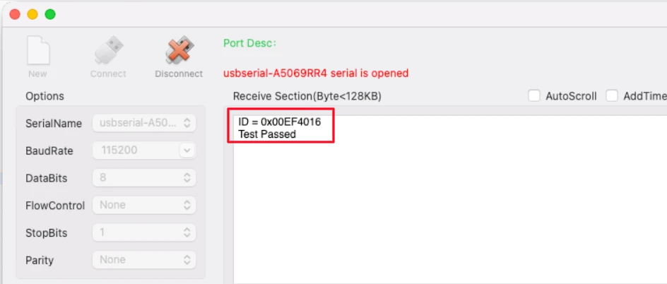
The console shows the ID of the W25Q module. For the W25Q16JV, the returned ID is 0x00EF4016 — EF is the Winbond manufacturer code and 4016 identifies the 16 Mbit variant. The “Test Passed” message confirms that read and write are working correctly.
STM32 USB MSC: Code and Results
We do not need to write anything in the main file. The entire code will be written in the usbd_storage_if.c file generated by the CubeMX. We will update this file to use the W25Q Flash module. Open the file and include the W25Q header at the top.
#include "W25Qxx.h"STORAGE_Init_FS — The W25Q module does not need any explicit initialization. It is ready to communicate over SPI as soon as the MCU starts. This function simply returns USBD_OK.
int8_t STORAGE_Init_FS(uint8_t lun)
{
    UNUSED(lun);
    return (USBD_OK);
}STORAGE_GetCapacity_FS — The W25Q16JV is 16 Mbit = 2 MB. With a block size of 4096 bytes, the total block count is 512. We pass 511 because the USB MSC requires one less than the actual count.
int8_t STORAGE_GetCapacity_FS(uint8_t lun, uint32_t *block_num, uint16_t *block_size)
{
UNUSED(lun);
*block_num = 511;
*block_size = 4096;
printf("Blocks=%lu Size=%u\r\n", *block_num, *block_size);
return (USBD_OK);
}STORAGE_IsReady_FS — No special handling needed. It will always return USBD_OK.
STORAGE_IsWriteProtected_FS — The Flash module is not write-protected. Return USBD_OK.
STORAGE_Read_FS — The host provides a logical block address. We multiply it by 4096 to get the physical byte address, and multiply the block length by 4096 to get the total byte count. We add a log every 100 blocks to track progress on the serial console.
int8_t STORAGE_Read_FS(uint8_t lun, uint8_t *buf, uint32_t blk_addr, uint16_t blk_len)
{
UNUSED(lun);
W25Q_ReadBytes(blk_addr * 4096, buf, blk_len * 4096);
if (blk_addr % 100 == 0) {
printf("READ: ADDR=%lu LEN=%u\r\n", blk_addr, blk_len);
}
return (USBD_OK);
}STORAGE_Write_FS — This is the most involved function. Since W25Q Flash memory cannot overwrite existing data, we must erase each sector before writing. And since the page size is 256 bytes, we write the 4 KB sector in sixteen 256-byte chunks.
int8_t STORAGE_Write_FS(uint8_t lun, uint8_t *buf, uint32_t blk_addr, uint16_t blk_len)
{
UNUSED(lun);
for (uint32_t b = 0; b < blk_len; b++) {
W25Q_EraseSector(blk_addr + b);
for (uint32_t i = 0; i < 4096; i += 256) {
W25Q_WriteBytes((blk_addr + b) * 4096 + i, &buf[b * 4096 + i], 256);
}
}
if (blk_addr % 100 == 0) {
printf("WRITE: ADDR=%lu LEN=%u\r\n", blk_addr, blk_len);
}
return (USBD_OK);
}The outer loop iterates over each requested block. For each block, we first erase the sector, then write 4096 bytes in 256-byte pages. The log prints after every 100 block addresses so we can track the operation on the serial console.
Here is the complete usbd_storage_if.c with all six functions implemented:
#include "usbd_storage_if.h"
#include "W25Qxx.h"
int8_t STORAGE_Init_FS(uint8_t lun)
{
    UNUSED(lun);
    return (USBD_OK);
}
int8_t STORAGE_GetCapacity_FS(uint8_t lun, uint32_t *block_num, uint16_t *block_size)
{
    UNUSED(lun);
    *block_num  = 511;
    *block_size = 4096;
    printf("Blocks=%lu Size=%u\r\n", *block_num, *block_size);
    return (USBD_OK);
}
int8_t STORAGE_IsReady_FS(uint8_t lun)
{
UNUSED(lun);
return (USBD_OK);
}
int8_t STORAGE_IsWriteProtected_FS(uint8_t lun)
{
UNUSED(lun);
return (USBD_OK);
}
int8_t STORAGE_Read_FS(uint8_t lun, uint8_t *buf, uint32_t blk_addr, uint16_t blk_len)
{
    UNUSED(lun);
    W25Q_ReadBytes(blk_addr * 4096, buf, blk_len * 4096);
    if (blk_addr % 100 == 0) {
        printf("READ: ADDR=%lu LEN=%u\r\n", blk_addr, blk_len);
    }
    return (USBD_OK);
}
int8_t STORAGE_Write_FS(uint8_t lun, uint8_t *buf, uint32_t blk_addr, uint16_t blk_len)
{
    UNUSED(lun);
    for (uint32_t b = 0; b < blk_len; b++) {
        W25Q_EraseSector(blk_addr + b);
        for (uint32_t i = 0; i < 4096; i += 256) {
            W25Q_WriteBytes((blk_addr + b) * 4096 + i, &buf[b * 4096 + i], 256);
        }
    }
    if (blk_addr % 100 == 0) {
        printf("WRITE: ADDR=%lu LEN=%u\r\n", blk_addr, blk_len);
    }
    return (USBD_OK);
}Formatting and Testing the Drive
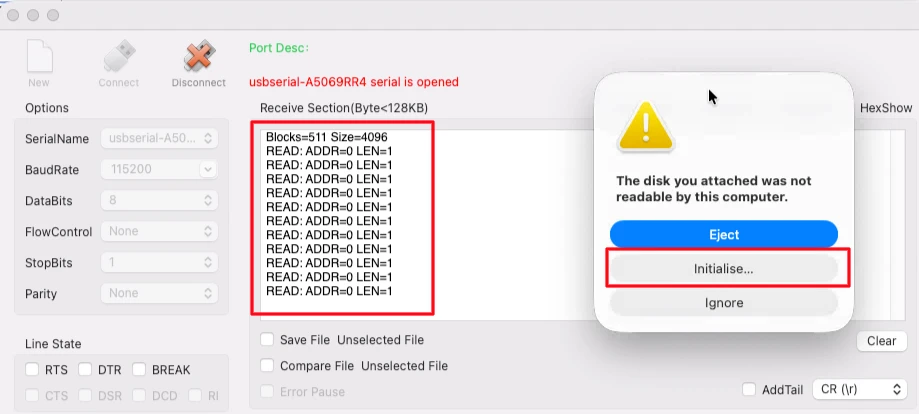
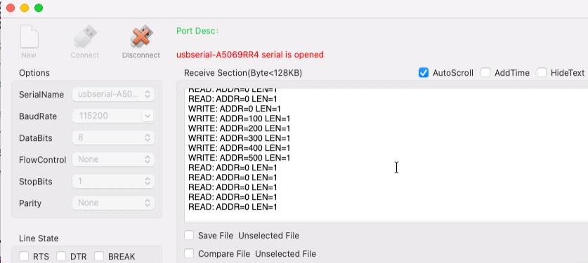
Flash the project and connect the USB cable to the board. Activity immediately appears on the serial console. The STORAGE_GetCapacity_FS function is called first, and the block count and block size are printed just as we defined them. After that, the host sends some read requests. Since there is no file system on the Flash memory yet, the operating system prompts us to format the drive. This is a one-time operation.
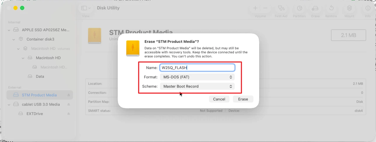
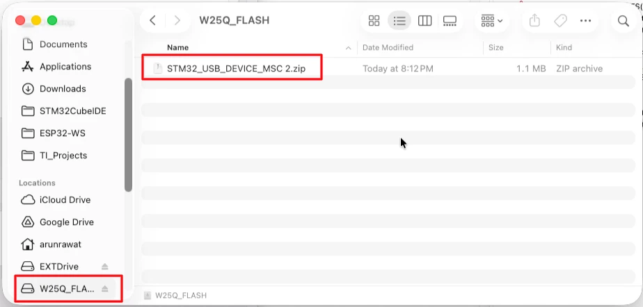
Open Disk Utility / Disk Management. The disk size shows approximately 2.1 MB, which is correct for a 16 Mbit device. Format it with FAT32 and Master Boot Record. Name it “W25Q_Flash”.
During formatting, write operations take place and log messages appear on the serial console after every 100 block addresses. Since the total block count is 512, the addresses go up to around 500. The formatting takes a bit of time, so keep checking the logs.
Once formatting is complete, the W25Q Flash drive appears as a new device in the file explorer. We can copy files into it just like any other external drive.
STM32 USB Mass Storage Class with W25Q NOR Flash — Video Tutorial
This video walks through using the W25Q SPI NOR Flash module as a USB Mass Storage device on the STM32. We configure SPI1 in CubeMX, integrate the W25Q library, implement the storage interface functions, and demonstrate the Flash module appearing as a removable drive on the computer — with full read, write, and power-cycle retention tests.
STM32 USB MSC W25Q — FAQs
Conclusion
In this tutorial, we used the STM32 USB Mass Storage Class with a W25Q SPI NOR Flash module to create a removable USB drive. We configured SPI1 in CubeMX, integrated the W25Q library, tested the Flash memory independently, and implemented all six storage interface functions in usbd_storage_if.c.
The key differences from the SD card project were the 4 KB block size, the mandatory sector-erase before each write, and the 256-byte page write limit. Once those are handled correctly in the write function, everything else works the same as before.
In the next part of the series, we will look at the USB Composite Device, where we will implement USB CDC alongside either the HID or Mass Storage Class, allowing two USB functions to run simultaneously over a single USB connection.
Download STM32 USB MSC W25Q NOR Flash Project
Open source CubeMX project files, W25Q library, and HAL source code, tested on real hardware. Free to use — support the work if it helped you.
Browse More STM32 USB Tutorials
STM32 USB Composite Class: CDC + HID Gamepad on One USB Port
STM32 USB HID: Combine Mouse and Keyboard on One Port
STM32 USB Host MSC: Read & Write USB Flash Drive with FatFs and FreeRTOS
STM32 USB Host HID: Read Keyboard and Mouse Data with STM32
STM32 USB Host Audio Class: Play WAV Files from SD Card

Subscribe
Login
0 Comments
Newest
