
Home ▸ STM32 Tutorials ▸ USB Tutorials ▸
Updated On: June 18, 2026
STM32 USB Host: Read and Write a USB Flash Drive with FatFs
This is Part 8 of the STM32 USB series. So far we have been working in USB device mode — CDC, HID, MSC, and the composite class. From this part onwards, we switch to USB host mode.
In this tutorial, the STM32 will act as a USB host. We will connect a FAT32-formatted USB flash drive to it, read a configuration file from the drive, apply the settings to the UART baud rate and LED blink delay at runtime, and also write a file back to the drive. Everything runs under FreeRTOS.
You can follow the other parts of this series here:
- Part 1: STM32 USB CDC: Virtual COM Port
- Part 2: STM32 USB HID Gamepad
- Part 3: STM32 USB HID Mouse and Keyboard
- Part 4: STM32 USB MSC SD Card as External Drive
- Part 5: STM32 USB MSC with W25Q NOR Flash
- Part 6: STM32 USB Composite Device (CDC+HID)
- Part 7: STM32 USB HID Mouse and Keyboard Combined

How STM32 USB Host MSC Works
In device mode, the STM32 appears to a PC as a peripheral, like a mouse, a keyboard, a virtual COM port etc. In host mode, the roles are reversed. The STM32 takes control of the bus and the connected device (a flash drive in this tutorial) is the peripheral.
The USB host stack on the STM32 handles enumeration automatically. Once a device connects, it goes through different states, such as connection, configuration, class activation and disconnection. The application code runs inside a callback called USBH_UserProcess in the usb_host.c file. We write our file read/write logic inside the HOST_USER_CLASS_ACTIVE state, which fires once the drive is mounted and ready.
FatFs is the file system layer that sits on top of the USB host stack. It gives us functions to operate on files, such as f_mount, f_open, f_read, f_write, f_close, etc.
FreeRTOS is added because the USB host stack works best with its own dedicated task, and it keeps the serial logging and LED blinking cleanly separated from the USB handling.
USB Host States and the Callback
The USBH_UserProcess callback is called internally by the USB host middleware. We handle four states inside it:
- HOST_USER_SELECT_CONFIGURATION : internal state, no action needed from us.
- HOST_USER_CONNECTION : the flash drive has been physically connected. The application state is set to
APPLICATION_START. - HOST_USER_CLASS_ACTIVE : the host has enumerated the device and it is ready to use. This is where we mount the drive and read/write files.
- HOST_USER_DISCONNECTION : the drive was removed. We unmount the file system cleanly.
The function USBH_UserProcess is called frequently during the runtime, hence the mounting and unmounting happen automatically on plug and unplug. We do not need to reset the board every time.
The config.txt File Format
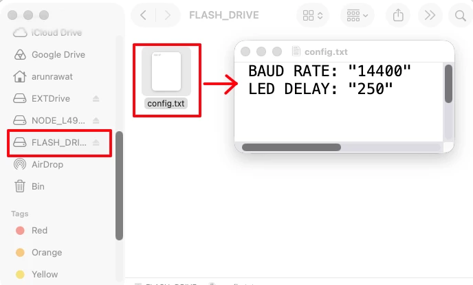
In this tutorial, the STM32 read a file, config.txt from the USB flash drive. The data retrieved from the file will then be used to configure the peripherals. This configuration file on the flash drive uses a simple key-value format:
BAUD RATE: "14400"
LED DELAY: "250"Each line has a key(BAUD RATE) , a colon(:), a space( ), and the value (14400) in double quotes. We will parse this data inside out code to retrieve the value (14400). This value will then be used to configure the UART peripheral, or the LED Delay time (250).
FreeRTOS Task Layout
I am also going to add the FreeRTOS with the USB. FreeRTOS will be used to run three tasks in parallel:
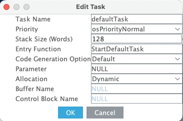
- defaultTask : initialises the USB host by calling
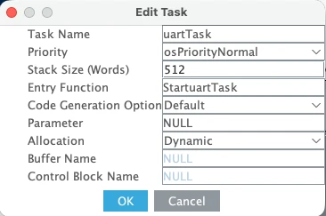
MX_USB_HOST_Init(). Stack: 128 words. - uartTask : prints “Hello World” every second. Checks a
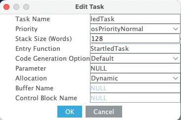
baudChangedflag and re-initialises the UART with the new baud rate if it is set. Stack: 512 words (printf needs space). - ledTask : toggles the LED at an interval set by
LED_Delay. Stack: 128 words.
When FreeRTOS is active, the USB host library handles its own processing through an internal task. Hence you will not find a call to the function MX_USB_HOST_Process() anywhere in the main file.
STM32 USB Host CubeMX Setup
We are going to configure everything in CubeMX — USB host, UART, GPIO, FreeRTOS.
USB Host Configuration
Go to Connectivity section and enable USB OTG FS in host-only mode. Pins PA11 and PA12 will be assigned as the USB D+ and D- pins. Enable VBUS sensing as well and the pin PA9 will be assigned as the VBUS Pin.
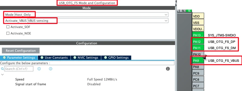
The VBUS sensing on PA9 tells the STM32 to monitor the VBUS line and manage power automatically. If the connected device has no self-power, the STM32 enables the supply. If the USB device do has its own power supply, STM32 will not supply any power to it.
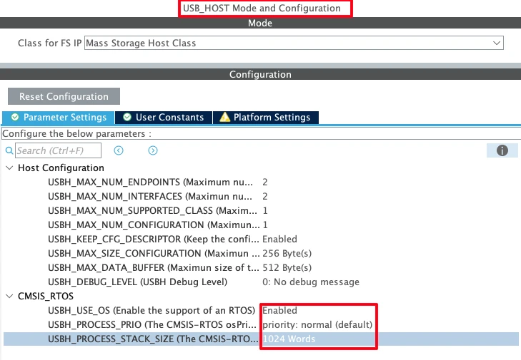
Next, go to Middleware -> USB Host and enable the Mass Storage Class. Leave parameters at default configuration.
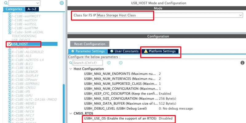
Note that the USBH_USE_OS is currently disabled as we have not enabled the FreeRTOS yet. Once enabled, this option will also enable automatically and we will configure it afterwards.
Also note that there is a warning showing in the Platform Settings. This is because the USB host middleware wants us to assign the VBUS pin in the platform settings for manual VBUS control. Since PA9 is already used for VBUS sensing, we cannot also assign it here in the Platform Settings. Hence we can ignore this warning. The sensing is already handling what the manual setting would otherwise do.
UART Configuration for Serial Logging
Now we will configure the LPUART1 for serial logging. I am choosing LPUART1 because on this Nucleo L496 board, the ST-Link Virtual Com Port pins are connected to LPUART1. This is shown in the image below.
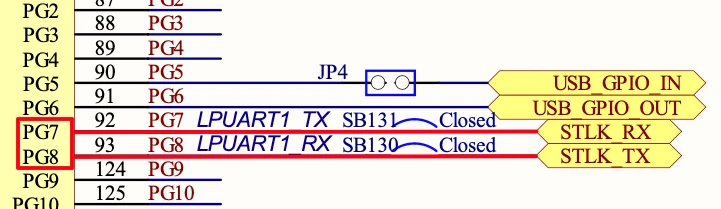
Go to Connectivity -> LPUART1 and enable it in the asynchronous mode. We also need to reassign the UART pins to PG7 (TX) and PG8 (RX), as according to the schematics, this is where the STLK_RX and STLK_TX pins are connected to.
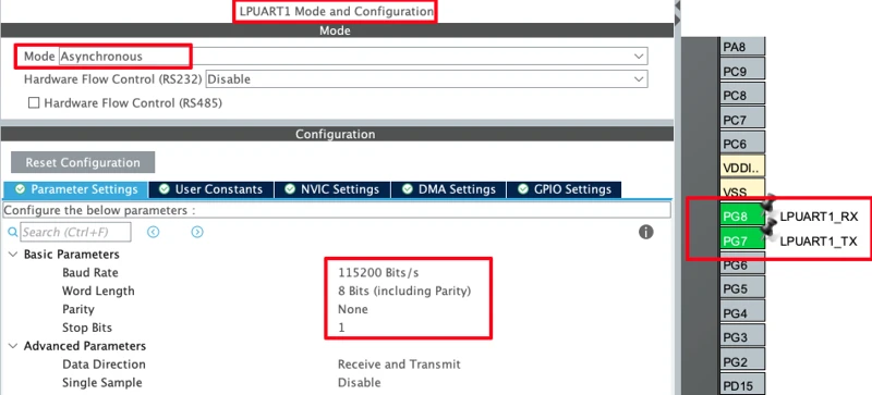
Also make sure the UART configured to baud rate of 115200, 8 bits, no parity and 1 stop bit.
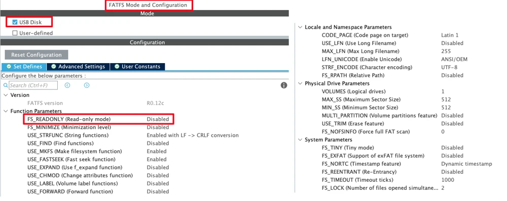
FatFs Configuration for File Handling
Next we will configure the FatFs Middleware to handle the file related operations. Go to Middleware -> FatFs and enable it for USB Disk. Make sure read-only mode is disabled so we can also write to the drive.
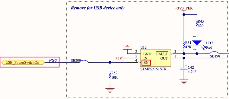
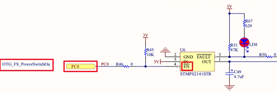
USB PowerSwitchOn Pin
The power switch IC is responsible for providing the power supply to the USB device. On Nulceo L496, the Power IC can be controlled by the pin PG6. Since PG6 is connected to the Enable pin (EN) of the power IC, we need to pull the PG6 High in order to activate the power supply to the USB device. If we do not do this, the USB host will not be enabled, and the connected USB device will not receive power or be detected.
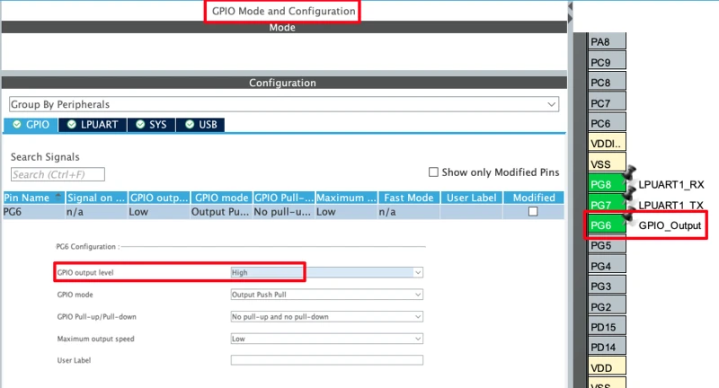
Configure PG6 as a GPIO output pin. In the GPIO settings for PG6, set the default output level to High.
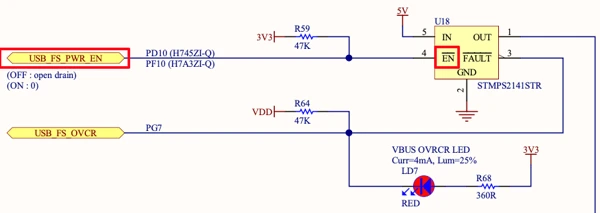
On some Development boards like STM32F407 Discovery or Nucleo H755ZI, the PowerSwitchOn pin is connected to the Enable Pin (), which is Active Low. So in these boards, after configuring the pin as output, it must be pulled Low to activate the Power Supply.
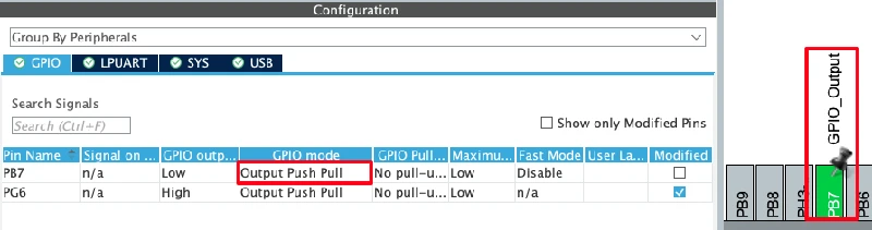
LED Pin Configuration
I am also going to configure an LED on Board. On Nucleo L496, the pin PB7 is connected to the blue LED as shown in the image below.
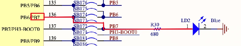
We just need to configure this pin in the output mode.
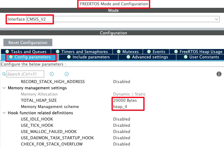
FreeRTOS Configuration
Now we will finally configure the FreeRTOS. Go to Middleware -> FreeRTOS and enable the CMSIS v2 interface. You can leave the parameters to default configuration, but make sure to set the heap size to at least 20–30 KB. The USB Host stack will require at least 4KB of the stack (or even more in some cases), hence set the heap size large enough to avoid any crash later.
Under Tasks and Queues section, we already have the default task. We will Add two more, uartTask and ledTask. The details of all three tasks are as follows:
- defaultTask — priority: Normal, stack: 128 words. It will be used to initialise the USB Host.
- uartTask — priority: Normal, stack: 512 words. It will print data to the serial console Periodically. Since printf() requires more stack size, provide at least 512 words for the stack.
- ledTask — priority: Normal, stack: 128 words. It will be used for the LED blinking. Not much of the stack is required here.
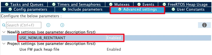
Next, go to Advanced Settings and enable Newlib Reentrant support. This is required when printf is called from multiple tasks.
Now if you check the USB Host configuration, the option USBH_USE_OS should be enabled. Although the internal task stack size defaults to 128 words, which is not enough when printf is called inside the USB callback. Set this to at least 1024 words.
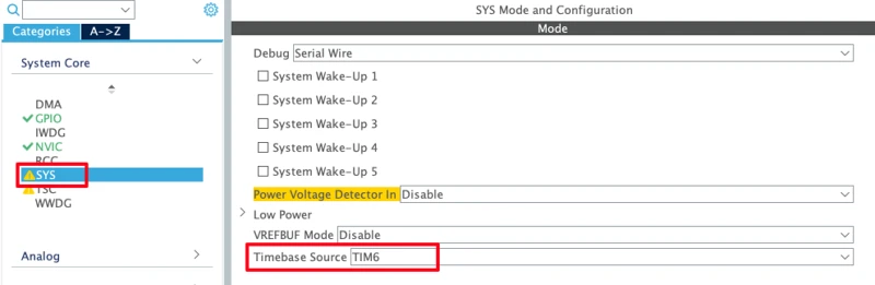
Since FreeRTOS uses SysTick, go to System Core -> SYS and set the HAL Time Base Source to TIM6. This avoids a conflict between the HAL tick and the RTOS scheduler.
Clock Configuration
I am going to use the internal HSI as the clock source and configure the PLL to reach 80 MHz.
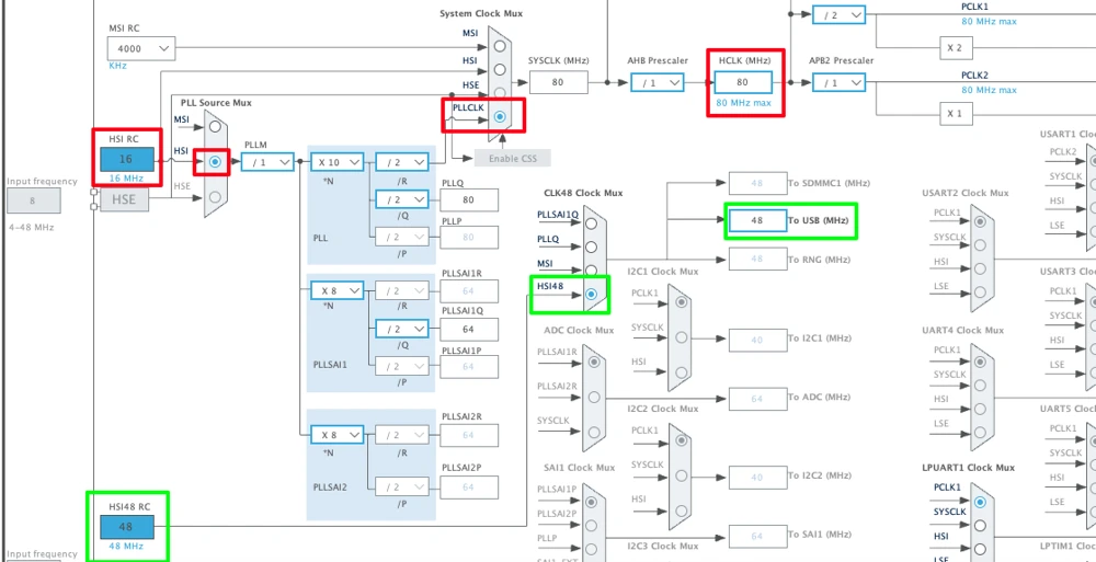
Under the clock tree, the USB peripheral requires exactly 48 MHz. On this board, we can use the dedicated HSI48 oscillator (48 MHz internal oscillator) specifically for USB.
STM32 USB Host Code and Result
printf Routing via UART
To use printf for serial logging, add this function in main.c:
int _write(int fd, unsigned char *buf, int len) {
if (fd == 1 || fd == 2) {
HAL_UART_Transmit(&hlpuart1, buf, len, 999);
}
return len;
}This will redirect printf output to LPUART1, which is connected to the STLink Virtual Com Port.
Shared Variables
Now Define three variables in main.c. These variables will be used to store the Baud Rate and LED Delay values.
uint32_t Baud_Rate = 115200;
uint16_t LED_Delay = 1000;
int baudChanged = 0;Baud_Rate and LED_Delay must have sensible defaults because the UART and LED tasks start immediately when the RTOS scheduler begins, before any USB drive is connected. If LED_Delay is zero, the LED task will spin without ever yielding and will crash the scheduler.
usb_host.c — File Read/Write and Config Parsing
We will write the entire code related to USB device inside thee usb_host.c file. Include ff.h at the top and declare the shared variables and FatFs objects as external variables.
#include "ff.h"
extern char USBHPath[4];
extern FATFS USBHFatFS;
FRESULT res;
FIL myFile;
char buffer[256];
extern uint32_t Baud_Rate;
extern uint16_t LED_Delay;
extern int baudChanged;Now write the full USBH_UserProcess callback. This handles all four USB host states. Although we will write our main code inside the HOST_USER_CLASS_ACTIVE.
static void USBH_UserProcess(USBH_HandleTypeDef *phost, uint8_t id)
{
switch(id)
{
case HOST_USER_SELECT_CONFIGURATION:
break;
case HOST_USER_DISCONNECTION:
Appli_state = APPLICATION_DISCONNECT;
printf("Application Disconnect\r\n");
if (f_mount(NULL, USBHPath, 0) == FR_OK)
{
printf("UnMount Successfully\r\n");
}
break;
case HOST_USER_CLASS_ACTIVE:
Appli_state = APPLICATION_READY;
printf("Application Ready\r\n");
res = f_mount(&USBHFatFS, USBHPath, 0);
if (res == FR_OK)
{
printf("Mount Successful\r\n");
/* ---- Read config.txt ---- */
res = f_open(&myFile, "config.txt", FA_READ);
if (res == FR_OK)
{
UINT bytesRead;
res = f_read(&myFile, buffer, sizeof(buffer) - 1, &bytesRead);
if (res == FR_OK)
{
buffer[bytesRead] = '\0';
printf("File Content\n%s\r\n", buffer);
char key[32];
char value[32];
char *line = strtok(buffer, "\r\n");
while (line != NULL)
{
if (sscanf(line, " %31[^:]: \"%31[^\"]\"", key, value) == 2)
{
if (strcmp(key, "BAUD RATE") == 0)
{
Baud_Rate = atoi(value);
baudChanged = 1;
printf("Baud Rate changed to %lu\r\n", Baud_Rate);
}
if (strcmp(key, "LED DELAY") == 0)
{
LED_Delay = atoi(value);
printf("LED Blink Delay is now %u\r\n", LED_Delay);
}
}
line = strtok(NULL, "\r\n");
}
}
else printf("Unable to read config.txt, ERROR %d\r\n", res);
f_close(&myFile);
}
else printf("Unable to open config.txt, ERROR %d\r\n", res);
if (f_open(&myFile, "test.TXT", FA_CREATE_ALWAYS|FA_WRITE) == FR_OK)
{
UINT bytesWritten;
if (f_write(&myFile, "This is a test file\n", 20, &bytesWritten) == FR_OK)
{
printf ("%d bytes written to file test.TXT\r\n", bytesWritten);
}
f_close(&myFile);
}
}
else
{
printf("Unable to Mount\r\n");
}
break;
case HOST_USER_CONNECTION:
Appli_state = APPLICATION_START;
printf("Application Start\r\n");
break;
default:
break;
}
}After mounting the USB driver, we call the function f_open with FA_READ opens an existing file. If the file is not in the root of the drive, you need to include the full path. In this case, the config.txt is in the root of the flash driver, so I just provided the name of the file.
Next, we read the content of the file and store them into the buffer array we defined in the beginning of this file. sizeof(buffer) - 1 reserves one byte for the null terminator that we add after the read.
Then we terminate the string stored in the buffer using buffer[bytesRead] = '\0'. Once the data is stored into the buffer, we need to extract the baud rate and delay values from it.
We call the tokenizer function strtok to split the data into lines. The *line will point to the content of the first line.
Next, we use the sscanf function to extract the key (BAUD RATE) and value (14400) from the first line. Once extracted, use the atoi function to convert the value (14400) from string to number format.
Inside the while loop, we keep calling strtok(NULL, "\r\n"), so the loop will keep running till all the lines are processed.
Finally we call the function f_close to close the opened file.
Here I am also performing a write operation to another file, test.txt. This file is not present on the USB device. Hence the function f_open uses FA_CREATE_ALWAYS and FA_WRITE. It will create a new file and then open the file for writing.
The we use the function f_write to write some test string into this file.
Finally we close the opened file using f_close.
main.c — FreeRTOS Tasks
Inside the main file, we only need to write the three task functions.
defaultTask just initialises the USB host. CubeMX generates this automatically:
void StartDefaultTask(void *argument)
{
MX_USB_HOST_Init();
for(;;)
{
osDelay(1);
}
}uartTask checks the baudChanged flag on every iteration. If it is set, the UART is de-initialised, the baud rate is updated in the handle, and it is re-initialised. This is the correct way to change the baud rate at runtime. We cannot just write a new value into the register while the peripheral is active.
void StartuartTask(void *argument)
{
for(;;)
{
if (baudChanged == 1)
{
printf("Switch the Baud Rate on Console to %lu\r\n", Baud_Rate);
HAL_UART_DeInit(&hlpuart1);
hlpuart1.Init.BaudRate = Baud_Rate;
HAL_UART_Init(&hlpuart1);
baudChanged = 0;
}
printf("Hello World from USB\r\n");
osDelay(1000);
}
}ledTask uses LED_Delay as the toggle interval. When the USB drive is read and the config is applied, this value changes and the blink rate updates without any restart:
void StartledTask(void *argument)
{
for(;;)
{
HAL_GPIO_TogglePin(GPIOB, GPIO_PIN_7);
osDelay(LED_Delay);
}
}The config.txt File
We will create a plain text file on the PC and save it as config.txt. The format must match exactly:
BAUD RATE: "14400"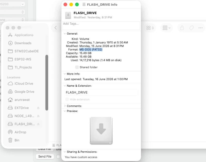
LED DELAY: "250"Copy this file to the root of a FAT32-formatted USB flash drive. If the drive is formatted as NTFS or exFAT, the STM32 FatFs stack will not be able to read it.
Output
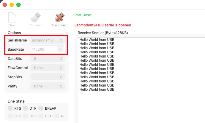
Once the project is built and flashed, open a serial monitor at 115200 baud, 8N1.
At startup, before the flash drive is connected, you will see the UART printing “Hello World from USB” every second and the LED blinking every 1000 ms.
The image below shows the serial console output at startup, before the USB drive is inserted.
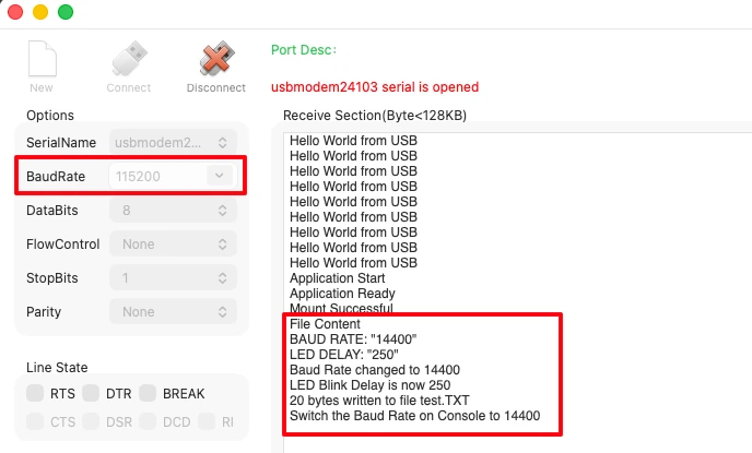
When the flash drive is plugged in, the output changes. The image below shows the full serial log after the USB flash drive is connected, including the mount confirmation and the config values being applied.
After we change the baud rate on the serial monitor to 14400, the “Hello World from USB” messages appear again. The LED also starts blinking at 250 ms, just as per the configuration of the config.txt file.

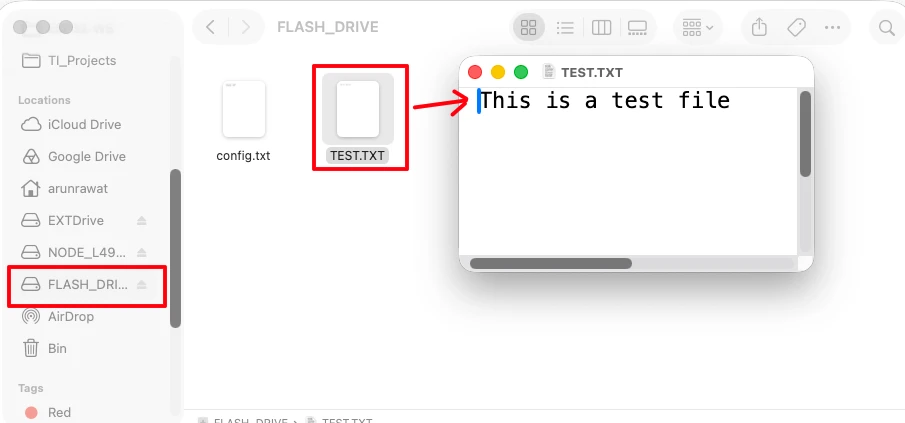
The image below shows the test.TXT file on the flash drive after reconnecting it to a PC, with the content written by the STM32.
STM32 USB Host MSC: Read & Write a USB Flash Drive — Video Tutorial
This video walks through the complete setup of the STM32 as a USB host using the Mass Storage Class. We configure the Nucleo L496 in CubeMX, add FatFs and FreeRTOS, read a configuration file from a FAT32 flash drive to update the UART baud rate and LED delay at runtime, and write a file back to the drive — all without resetting the board.
STM32 USB Host MSC — FAQs
Conclusion
We configured the STM32 Nucleo L496 as a USB host, used the Mass Storage Class with FatFs to mount a FAT32 flash drive, read a configuration file from it to update the UART baud rate and LED blink delay at runtime. We also wrote a test file back to the drive, and all running under FreeRTOS.
The key things to get right are: enabling the USB power switch pin (PG6 high on the L496), using the HSI48 oscillator for the exact 48 MHz USB clock, setting the USB host task stack to at least 1024 words, and initialising Baud_Rate and LED_Delay with safe defaults before the RTOS starts.
The plug-and-play behaviour (mount on connect, unmount on disconnect) comes along with the USB host callback, so the flash drive can be swapped at any time without resetting the board.
In the next part of this series, we will switch to the USB HID host class and read data from a mouse connected to the STM32.
Download STM32 USB Host MSC FatFs FreeRTOS Project
Open source CubeMX project files and HAL source code, tested on real hardware. Free to use — support the work if it helped you.
Browse More STM32 USB Tutorials

STM32 USB Composite Class: CDC + HID Gamepad on One USB Port

STM32 USB HID: Combine Mouse and Keyboard on One Port

Subscribe
Login
0 Comments
Newest
