
Home ▸ STM32 Tutorials ▸ Modbus ▸ TCP ▸
Updated On: August 26, 2026
STM32 Modbus TCP Server: Read Discrete Inputs Using Mongoose
This is the first tutorial in the Modbus TCP series. In this series, we will configure an STM32 as a Modbus server (also called a slave). The server will respond to queries from a Modbus client. Later in the series, we will also make the STM32 act as a Modbus client.
In this tutorial specifically, we will see how to read discrete inputs from the STM32 Modbus TCP server. We will use a PC application as the Modbus client. The client will connect to the server and request the state of the physical inputs connected to the STM32. We will also visualize those inputs in real time using the Mongoose web UI.
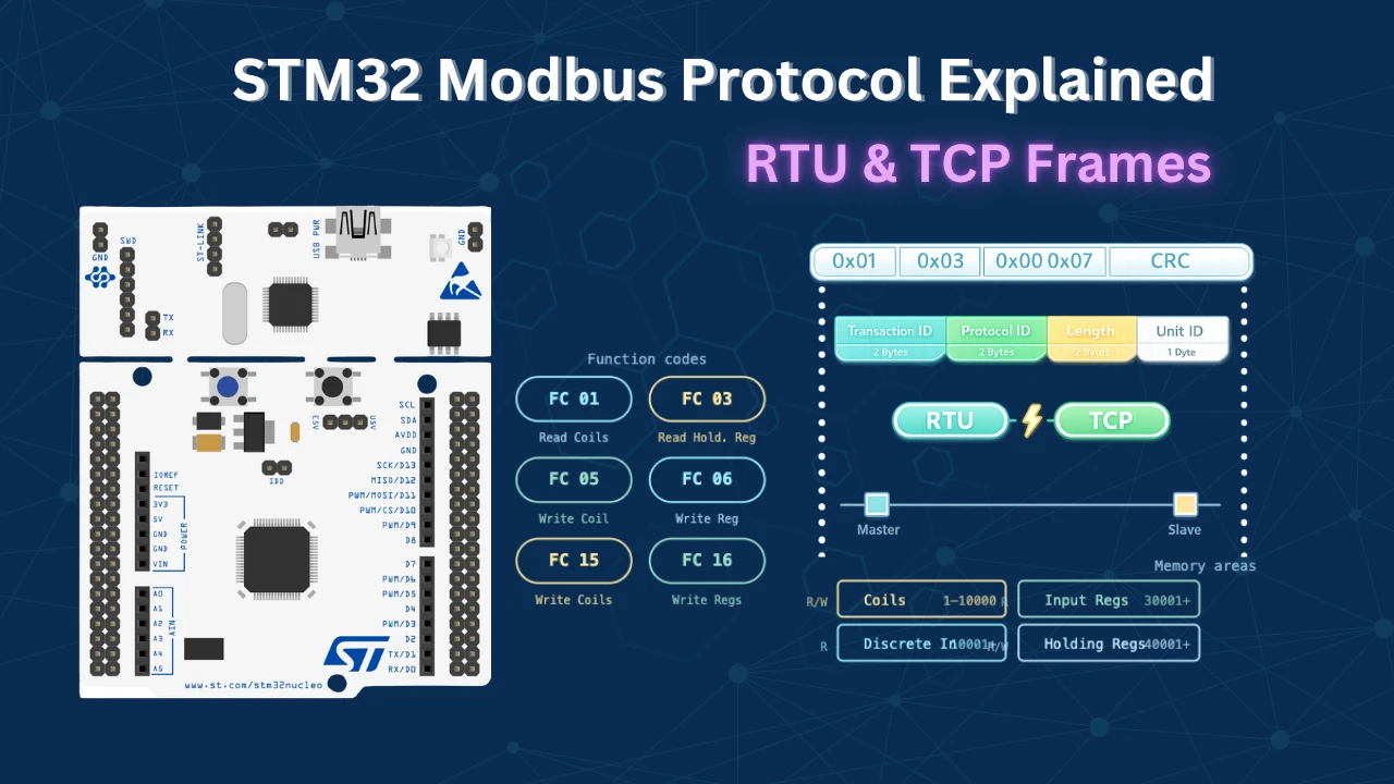
Before diving in, you should read the previous post: Modbus TCP Protocol Explained: Frame Structure, MBAP Header, and Function Codes. That post covers everything you need to understand how Modbus TCP actually works — the structure of the ADU frame, how the 7-byte MBAP header is built, what each field (Transaction ID, Protocol ID, Length, and Unit Identifier) means, how the PDU carries the function code and data, and why there is no checksum unlike Modbus RTU. We will not repeat those fundamentals here.
For this entire series, I will be using the STM32 Nucleo H755ZI development board and the Mongoose networking library.
Other parts of the STM32 Modbus TCP Server series:
- Modbus TCP Protocol Explained
- Part 2 – STM32 Modbus TCP Server: Read and Write Coils
- Part 3 – STM32 Modbus TCP Server: Read and Write Holding Registers
- Part 4 – STM32 Modbus TCP Server: Read Input Registers
What Are Discrete Inputs in Modbus?
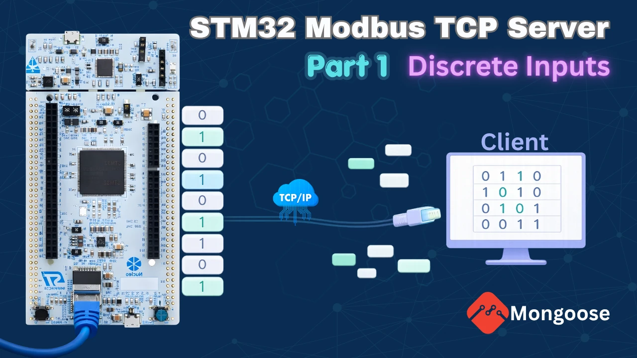
Discrete inputs are single-bit, read-only signals. Each input has only two possible states — 1 (ON) or 0 (OFF). They represent physical binary signals connected to the hardware. A switch, a push button, or a sensor trigger are all good examples.
The key point is that discrete inputs are hardware-driven. We can only read them. We cannot write to them from software.
In this project, we connect 10 switches to the GPIO pins on the STM32. Each pin has a pull-up resistor enabled. So by default, each pin reads 1. When we close the switch and connect the pin to ground, it reads 0.

Function Code for Discrete Inputs
We use Function Code 02 (0x02) to read discrete inputs over Modbus TCP. This is a read-only operation. The client sends a request with the starting address and the number of inputs to read. The server responds with the current state of each input packed into bytes.
Modbus TCP Request and Response Frame
The diagram below shows the byte-level structure of both the request and response frames for reading discrete inputs.

I have already explained the MBAP header and PDU in detail in the previous tutorial. Here we will only look at the data part.
A few things to note here:
- The Length field is different in the request (0x0006) and response (0x0005). The server always recalculates this. It is never copied from the request.
- The Transaction ID is echoed back by the server unchanged. This lets the client match the response to the correct request.
- For 10 inputs, the server returns 2 bytes of data. The states are packed LSB first — bit 0 of byte 1 = Input 1, bit 1 = Input 2, and so on up to bit 1 of byte 2 = Input 10.
Wiring and CubeMX Configuration
Before writing any code, we need to generate the base project using the Mongoose web UI wizard. The wizard takes care of all the board-specific initialization and networking setup.
Create a New Project in the Web UI Wizard
We start by creating a new project in the Mongoose web UI. Here are the steps:
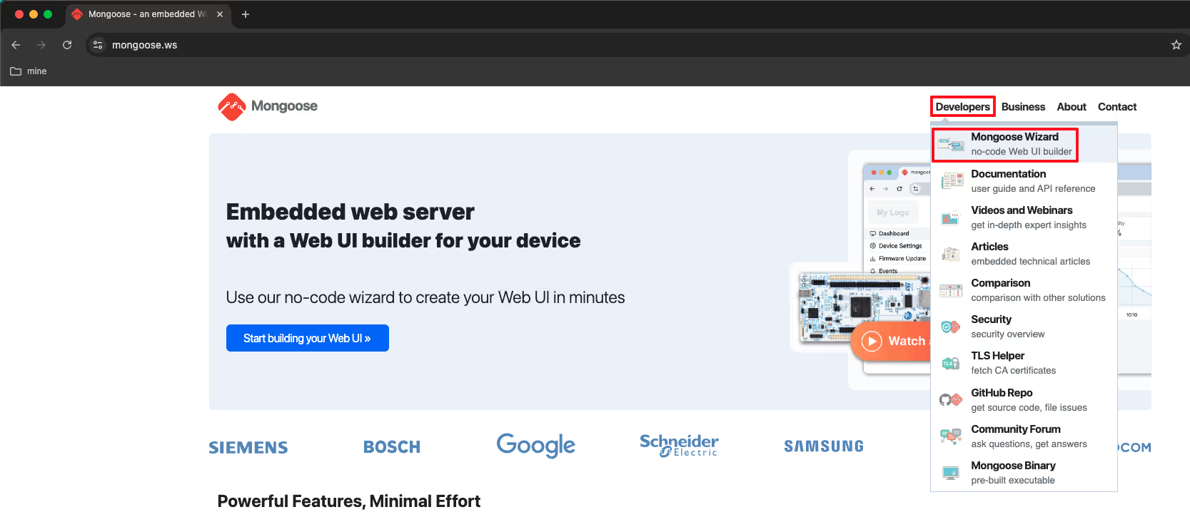
- Go to mongoose.ws and open the Mongoose Wizard.
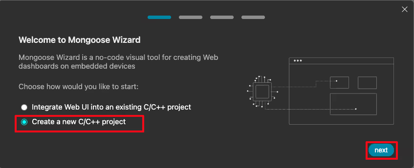
- Click New to create a new project.
- The next screen asks for a destination directory. This is where the generated project files will be saved on your computer. Select a folder and move to the next step.
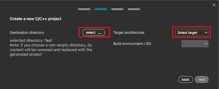
- Now we need to select the Target Architecture. Mongoose supports several STM32F and STM32H series boards. I am using the STM32H755 Nucleo board, so I selected that from the dropdown.

- Next select the Build Environment and the RTOS. I chose STM32CubeIDE as the IDE and No RTOS since we are keeping things simple for now.

- The wizard then asks us to pick a starting dashboard template. I selected the one with a single LED toggle. It gives us something to start with rather than building from a completely blank canvas.
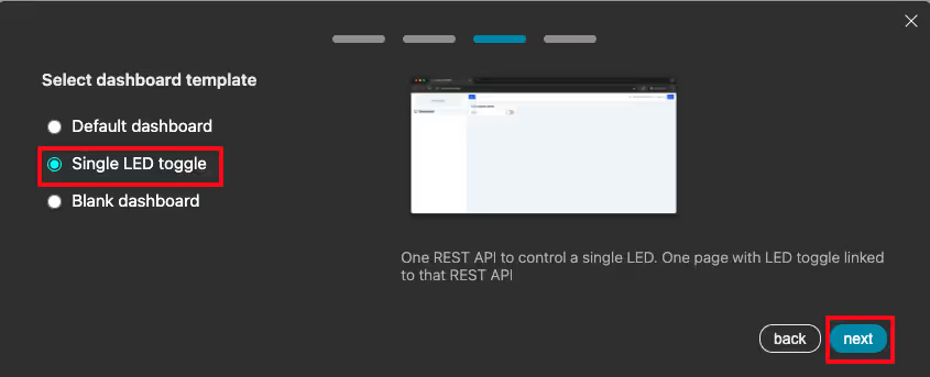
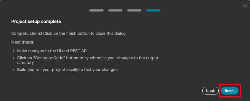
- Click Finish. The wizard now opens the web UI editor.
Enable Modbus TCP Server in Settings
After selecting the dashboard, go to the Settings page. Enable the Modbus TCP Server option. Leave the port set to 502, which is the standard Modbus TCP port.

Next, click Generate Project. The wizard will generate the full project inside the selected directory. The project includes:
- An IOC file for CubeMX configuration.
- A Mongoose folder containing all Mongoose-related files.

Note:
Do not modify any files inside the Mongoose folder. If we regenerate the project from the wizard, everything in that folder gets overwritten.
Static IP Configuration for STM32 Modbus TCP
After importing the project into the IDE, we need to test it to make sure everything is configured correctly.
By default, Mongoose uses DHCP to assign an IP address. Since I am connecting the Ethernet cable directly to the PC, there is no DHCP server on the network. So we need to configure a static IP manually.
Open the Mongoose configuration file mongoose_config.h and uncomment the static IP definitions. Set the IP address, gateway, and subnet mask based on your PC’s network settings. For example:
#define MG_TCPIP_IP   MG_IPV4(192, 168, 0, 10)
#define MG_TCPIP_GW   MG_IPV4(192, 168, 0, 1)
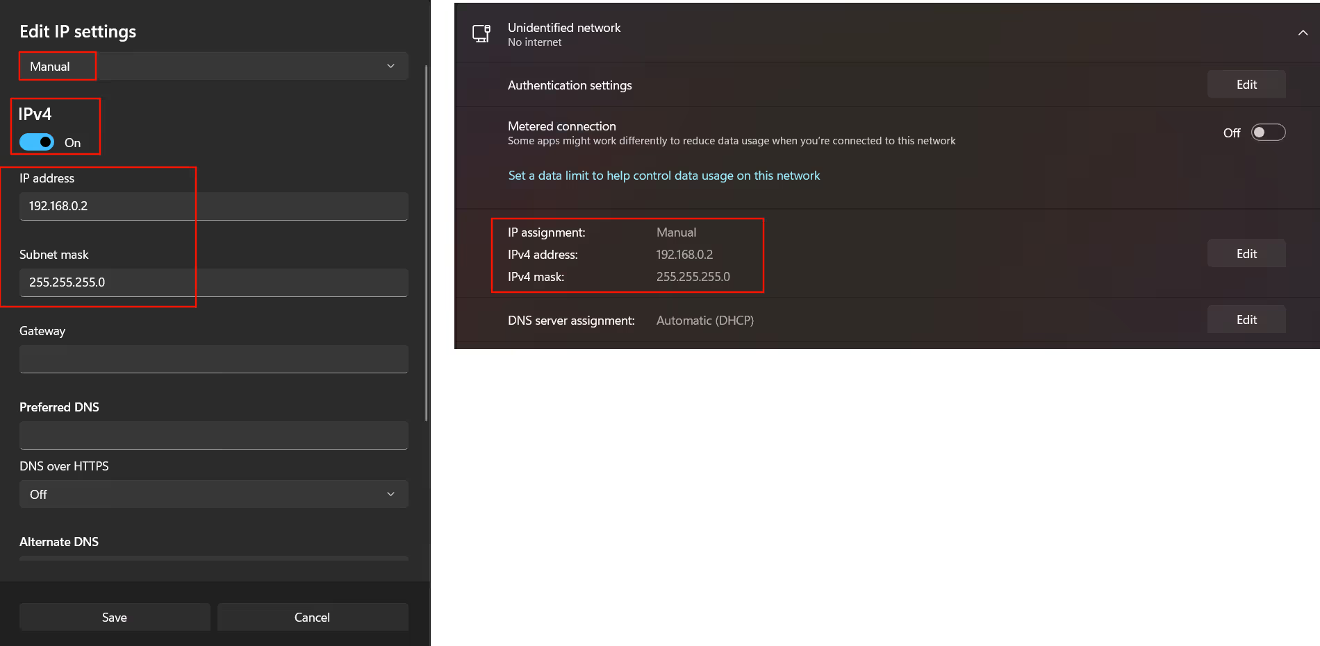
#define MG_TCPIP_MASK MG_IPV4(255, 255, 255, 0)You need to manually set your computer’s Ethernet adapter to be in the same subnet as the static IP.
On Windows:
The image below shows the IPv4 settings for a Windows computer.
On Mac:
The image below shows the network settings on a Mac.
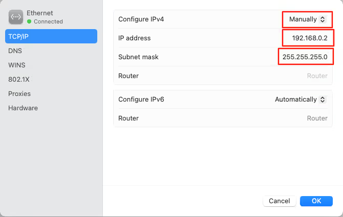
Make sure the IP address you assign to the STM32 is in the same subnet as your PC. For example, if your PC’s IP is 192.168.0.5, the STM32 should be something like 192.168.0.10.
Output
Now flash the project and reset the board. The serial console will print the assigned IP address on boot. Open that IP in a browser and the default Mongoose web UI will load. We will not use it right now, but it confirms that the network stack is running correctly.
The image below shows the serial console output after the board boots up successfully with the static IP address assigned.

Pin Assignment and Core Selection
Now we need to configure the physical input pins on the STM32. We have 10 inputs connected to different GPIO pins. Each input is connected to ground through a switch. When the switch is closed, the pin reads 0. When the switch is open, the pull-up resistor pulls the pin high to VDD, so it reads 1.
The image below shows how the inputs are connected to the STM32 Nucleo H755ZI.

Inside STM32CubeMX, configure the following pins as GPIO Input and assign them to the Cortex-M7 core. Then rename each pin as shown:
| Pin | Label |
|---|---|
| PA3 | INPUT1 |
| PC0 | INPUT2 |
| PC3 | INPUT3 |
| PB1 | INPUT4 |
| PC2 | INPUT5 |
| PF11 | INPUT6 |
| PF14 | INPUT7 |
| PF15 | INPUT8 |
| PD0 | INPUT9 |
| PD1 | INPUT10 |
Assigning the pins to the correct core is important on a dual-core board. The labels (e.g., INPUT1, INPUT2) allow CubeMX to auto-generate clean definitions like INPUT1_GPIO_Port and INPUT1_Pin, which we will use directly in the code.
Enable Pull-Up Mode for All Inputs
Go to System Core → GPIO. Set all 10 input pins to Pull-up mode. This ensures that each pin reads 1 by default when no switch is pressed. When the switch is closed and the pin is connected to ground, it reads 0.

Modbus Server Code, Configuration and Testing
With the project configured, we can now write the Modbus server logic. We need to handle the incoming read request from the client and return the actual state of the GPIO pins.
Define the Input Structure and Array
We start by defining a structure to represent a single input. It holds the GPIO port and pin for that input.
typedef struct {
    GPIO_TypeDef *port;
    uint16_t pin;
} input_t;Next, we create an array of this structure for all 10 inputs. We use the CubeMX-generated labels directly.
input_t inputs[10] = {
{INPUT1_GPIO_Port, INPUT1_Pin},
{INPUT2_GPIO_Port, INPUT2_Pin},
{INPUT3_GPIO_Port, INPUT3_Pin},
{INPUT4_GPIO_Port, INPUT4_Pin},
{INPUT5_GPIO_Port, INPUT5_Pin},
{INPUT6_GPIO_Port, INPUT6_Pin},
{INPUT7_GPIO_Port, INPUT7_Pin},
{INPUT8_GPIO_Port, INPUT8_Pin},
{INPUT9_GPIO_Port, INPUT9_Pin},
{INPUT10_GPIO_Port, INPUT10_Pin},
};Using the CubeMX labels keeps the code clean and easy to read.
Write the Read Input Function
Now we write a function to read the state of a single input. The Modbus handler calls this function once for each input the client requests. The parameter i is the index of the input, that the client wants to read.
bool READ_INPUTS (uint16_t i)
{
return (HAL_GPIO_ReadPin(inputs[i].port, inputs[i].pin));
}If the pin is high, the function returns true. If the pin is low, it returns false. That value gets passed back to the Modbus handler.
Register the Custom Modbus Handler
Open mongoose_glue.c and locate the generated Modbus handler function. Copy it into the main file. We should not modify the code inside mongoose_glue.c directly, because regenerating the project will overwrite it.
Inside our copied function, we replace the default coil-read logic with the discrete input function code. The relevant definition for reading discrete inputs is MG_MODBUS_FUNC_READ_DISCRETE_INPUTS. We use it to handle the incoming request.
void my_modbus_handler(struct mg_modbus_req *req) {
if (req->func == MG_MODBUS_FUNC_READ_DISCRETE_INPUTS) {
for (uint16_t i = 0; i < req->len; i++) {
req->u.bits[i] = READ_INPUTS(req->addr + i);
}
}
else {
req->error = MG_MODBUS_ERR_DEVICE_FAILURE;
}
}Since we named our function my_modbus_handler, it does not match the default glue function name. We need to register it manually. After Mongoose is initialized in main(), we call:
mongoose_set_modbus_handler(my_modbus_handler);This tells Mongoose to use our custom function for all incoming Modbus requests.
Full Code (Modbus Handler Section)
typedef struct {
    GPIO_TypeDef *port;
    uint16_t pin;
} input_t;
input_t inputs[10] = {
    {INPUT1_GPIO_Port, INPUT1_Pin},
    {INPUT2_GPIO_Port, INPUT2_Pin},
    {INPUT3_GPIO_Port, INPUT3_Pin},
    {INPUT4_GPIO_Port, INPUT4_Pin},
    {INPUT5_GPIO_Port, INPUT5_Pin},
    {INPUT6_GPIO_Port, INPUT6_Pin},
    {INPUT7_GPIO_Port, INPUT7_Pin},
    {INPUT8_GPIO_Port, INPUT8_Pin},
    {INPUT9_GPIO_Port, INPUT9_Pin},
    {INPUT10_GPIO_Port, INPUT10_Pin},
};
bool READ_INPUTS (uint16_t i)
{
return (HAL_GPIO_ReadPin(inputs[i].port, inputs[i].pin));
}
void my_modbus_handler(struct mg_modbus_req *req) {
if (req->func == MG_MODBUS_FUNC_READ_DISCRETE_INPUTS) {
for (uint16_t i = 0; i < req->len; i++) {
req->u.bits[i] = READ_INPUTS(req->addr + i);
}
}
else {
req->error = MG_MODBUS_ERR_DEVICE_FAILURE;
}
}
int main ()
{
// other initializations
mongoose_init();
mongoose_set_modbus_handler(my_modbus_handler);
for (;;) {
mongoose_poll();
}
while (1){}
}Build and flash the project. After reset, the serial console confirms the server is running and the IP address is printed.
Testing with a Modbus TCP Client
With the server running on the STM32, we can now connect a Modbus TCP client and send read requests.
Configure Simply Modbus TCP Client
I am using Simply Modbus TCP Client on Windows. Since it is not available on Mac, I am running it inside a virtual machine. Configure the client as follows:

- Mode: TCP
- Server IP: The static IP we assigned to the STM32
- Port: 502
- Slave ID: 10 (any value works for a single server)
- Function Code: 2 (Read Discrete Inputs)
- Starting Address: 10001
- Quantity: 10
Output
The images below shows the current states of the discrete inputs connected to STM32 and the response received by the client, when requested the data from the modbus server.


When all 10 wires are connected to ground, all inputs read 0. When we disconnect a few wires, the corresponding inputs switch to 1. For example, with inputs 2, 5, 7, and 10 disconnected, the expected response is:
0 1 0 0 1 0 1 0 0 1The client returns exactly that result.
Reading the Modbus TCP Frame
Let’s understand what is actually being exchanged over the network.
Client Request (sent bytes):
| Field | Size | Value | Description |
|---|---|---|---|
| Transaction ID | 2 bytes | 0x0001 | Unique ID per transaction |
| Protocol ID | 2 bytes | 0x0000 | Fixed for Modbus TCP |
| Length | 2 bytes | 0x0006 | Remaining byte count |
| Slave ID | 1 byte | 0x0A | Server address |
| Function Code | 1 byte | 0x02 | Read Discrete Inputs |
| Start Address | 2 bytes | 0x0000 | First input address |
| Quantity | 2 bytes | 0x000A | Number of inputs (10) |
Server Response (received bytes):
| Field | Size | Value | Description |
|---|---|---|---|
| Transaction ID | 2 bytes | 0x0001 | Echoed from request |
| Protocol ID | 2 bytes | 0x0000 | Fixed for Modbus TCP |
| Length | 2 bytes | 0x0005 | Remaining byte count |
| Slave ID | 1 byte | 0x0A | Server address |
| Function Code | 1 byte | 0x02 | Read Discrete Inputs |
| Byte Count | 1 byte | 0x02 | Number of data bytes |
| Input Data | 2 bytes | — | Actual input states |
The 10 input states are packed into 2 bytes — 8 bits in the first byte and 2 bits in the second.
Real-Time Web UI for Discrete Inputs
The Modbus client confirms our data is correct. Now we will set up the Mongoose web UI to display the real-time state of all 10 inputs directly in a browser.
We go back to the Mongoose web UI wizard and make the following changes before regenerating the project.
Set Up the REST API Endpoint
Go to the REST API section:
- Delete the default LED endpoint.
- Create a new endpoint named inputs.
- Set the type to Array so all 10 inputs are handled through a single endpoint.
- Add one attribute of type Boolean.
- Set the endpoint to Read Only, since discrete inputs are hardware-based and cannot be changed from software.

Configure the Dashboard in the Wizard
On the dashboard page, we modify the default LED container:
- Rename the container to Discrete Inputs.
- Delete the second LED element — we only need one template element.
- Rename the LED label to
INPUT ${i+1}. - Link the toggle element and the container to the
inputsAPI variable.


The ${i+1} is a template string. The variable i starts from 0, so adding 1 gives us labels like INPUT 1, INPUT 2, and so on.
Finally, go to Settings and enable WebSocket. We need WebSocket so the UI can receive continuous real-time updates from the server.

Click Generate Code. This only overwrites the Mongoose folder — our CubeMX configuration and custom code in the main file remain untouched.
Update the Getter Function in Code
After regeneration, open mongoose_glue.c. We will see new generated code: a structure for the inputs array along with a getter and a setter function. Since our inputs are read-only, we only need the getter. Copy the inputs array and the getter function into the main file.
We need to make two changes to the copied function:
- Increase the array size to 10.
- Rename the function and the array to avoid conflicts with the glue file.
static struct inputs dis_inputs[] = {
{false},{false},{false},{false},{false},{false},{false},{false},{false},{false},
};Inside the getter function, we add a for loop right after the size check. This loop reads each physical input and stores its state into the structure that gets sent to the web UI.
bool my_get_inputs(struct inputs *data, size_t i) {
size_t array_size = sizeof(dis_inputs) / sizeof(dis_inputs[0]);
if (i >= array_size) return false;
for (int j =0; j<array_size; j++)
{
dis_inputs[j].level = READ_INPUTS(j);
}
*data = dis_inputs[i]; // Sync with your device
return true;
}We reuse the READ_INPUTS() function here. It keeps the code consistent and clean.
Register the WebSocket Reporter
Just like we registered the Modbus handler, we need to register the getter function with Mongoose. We also need to set up a WebSocket reporter so the UI receives regular updates.
// Register the getter (no setter since inputs are read-only)
mongoose_set_http_handlers("inputs", my_get_inputs, NULL);
// Send updates to the web UI every 200ms
mongoose_add_ws_reporter(200, "inputs");The first parameter of mongoose_add_ws_reporter is the update interval in milliseconds. The 200 ms works well here. STM32 will send regular updates to the UI every 200ms.
Full Code (Web UI Section)
typedef struct {
GPIO_TypeDef *port;
uint16_t pin;
} input_t;
input_t inputs[10] = {
    {INPUT1_GPIO_Port, INPUT1_Pin},
    {INPUT2_GPIO_Port, INPUT2_Pin},
    {INPUT3_GPIO_Port, INPUT3_Pin},
    {INPUT4_GPIO_Port, INPUT4_Pin},
    {INPUT5_GPIO_Port, INPUT5_Pin},
    {INPUT6_GPIO_Port, INPUT6_Pin},
    {INPUT7_GPIO_Port, INPUT7_Pin},
    {INPUT8_GPIO_Port, INPUT8_Pin},
    {INPUT9_GPIO_Port, INPUT9_Pin},
    {INPUT10_GPIO_Port, INPUT10_Pin},
};
bool READ_INPUTS (uint16_t i)
{
	return (HAL_GPIO_ReadPin(inputs[i].port, inputs[i].pin));
}
void my_modbus_handler(struct mg_modbus_req *req) {
  if (req->func == MG_MODBUS_FUNC_READ_DISCRETE_INPUTS) {
    for (uint16_t i = 0; i < req->len; i++) {
      req->u.bits[i] = READ_INPUTS(req->addr + i);
    }
  }
  else {
    req->error = MG_MODBUS_ERR_DEVICE_FAILURE;
  }
}
static struct inputs dis_inputs[] = {
  {false},{false},{false},{false},{false},{false},{false},{false},{false},{false},
};
bool my_get_inputs(struct inputs *data, size_t i) {
  size_t array_size = sizeof(dis_inputs) / sizeof(dis_inputs[0]);
  if (i >= array_size) return false;

  for (int j =0; j<array_size; j++)
  {
	  dis_inputs[j].level = READ_INPUTS(j);
  }
  *data = dis_inputs[i];  // Sync with your device
  return true;
}
int main ()
{
// other initializations
mongoose_init();
mongoose_set_modbus_handler(my_modbus_handler);
mongoose_set_http_handlers("inputs", my_get_inputs, NULL);
mongoose_add_ws_reporter(200, "inputs");
for (;;) {
mongoose_poll();
}
while (1){}
}Output
The image below shows the web UI displaying all 10 discrete inputs with their real-time states. We can also confirm that the web UI and the Modbus client are reading from the same source. When we send a read request from the Modbus client, the response matches exactly what is shown on the web UI.

STM32 Modbus TCP Server: Read Discrete Inputs — Video Tutorial
This video walks through the complete setup of an STM32 Modbus TCP server using the Mongoose networking library. We configure 10 discrete inputs on the STM32 Nucleo H755ZI, write the Modbus handler, test it using a Modbus TCP client, and display the real-time input states on the Mongoose web UI.
STM32 Modbus TCP Discrete Inputs — Frequently Asked Questions
Conclusion
In this tutorial, we configured the STM32 Nucleo H755ZI as a Modbus TCP server using the Mongoose networking library. We set up 10 discrete inputs on the GPIO pins, configured them in STM32CubeMX with pull-up mode, and wrote a custom Modbus handler to respond to FC02 read requests from the client. We also tested the setup using Simply Modbus TCP Client and verified the raw request and response frames byte by byte.
This setup is useful in real industrial applications where a master device needs to monitor the state of physical inputs — switches, sensors, or push buttons — over a network. Instead of polling each device individually over serial, Modbus TCP lets us do this over Ethernet with a clean and standardized protocol. The Mongoose web UI adds another layer of visibility by displaying all 10 input states in real time directly in a browser.
In the next tutorial, we will work with coils. Unlike discrete inputs, coils are read-write. The Modbus client will be able to both read and write them, and we will connect LEDs to the STM32 to physically see the outputs being controlled over Modbus TCP.
Download STM32 Modbus TCP Server Discrete Inputs Project
Open source CubeMX project files and HAL source code, tested on real hardware. Free to use — support the work if it helped you.
Browse More STM32 Modbus TCP Tutorials
STM32 LWIP Modbus TCP Tutorial: Server Setup (Part 1)
STM32 Modbus TCP (Part 2): Read Holding & Input Registers
STM32 Modbus TCP Server using LWIP – Part 3: Writing Holding Registers (FC06 & FC16)
STM32 Modbus TCP Server using LWIP – Part 4: Reading Coils and Discrete Inputs (FC01 & FC02)
STM32 Modbus TCP Server using LWIP – Part 5: Writing Coils (FC05 & FC15)

Subscribe
Login
0 Comments
Newest

