
Home ▸ STM32 Tutorials ▸ Modbus ▸ TCP ▸
Updated On: August 26, 2026
STM32 Modbus TCP Server – Read and Write Coils using Mongoose
This is Part 2 of the STM32 Modbus TCP Server series. In Part 1, we configured the STM32 as a Modbus TCP server and used function code 2 to let a client read the state of 10 discrete inputs — physical switches connected to the board.
In this part, we move to coils. The STM32 is still the TCP server. The Modbus client can now both read and write coils. We will also connect this to a Mongoose web UI dashboard, so coil states can be read and toggled directly from a browser as well.
We are continuing in the same CubeIDE project from Part 1, just updating the wizard configuration and replacing the input-related code with coil-related code.
Here are the other parts of the STM32 Modbus TCP Series:
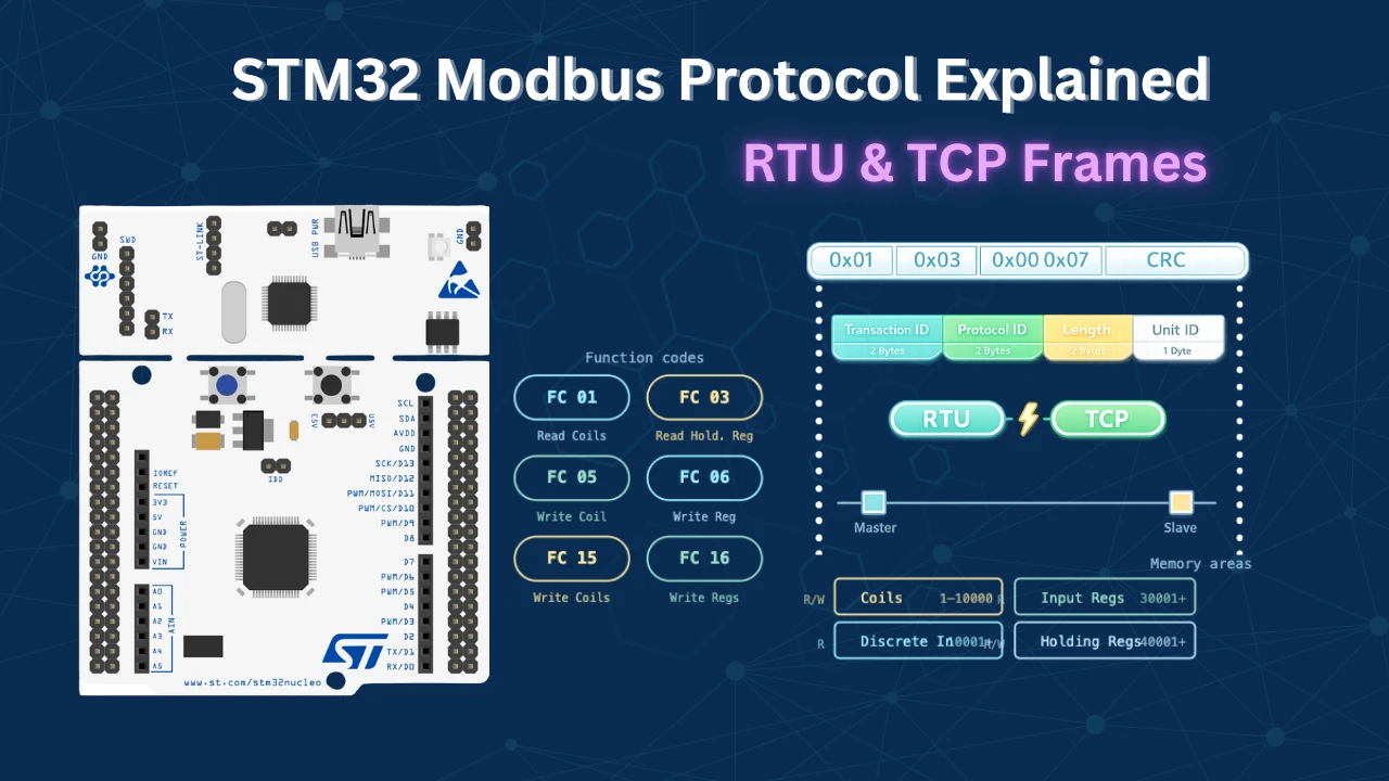
- Modbus TCP Protocol Explained
- Part 1 – STM32 Modbus TCP Server: Reading Discrete Inputs
- Part 3 – STM32 Modbus TCP Server: Read and Write Holding Registers
- Part 4 – STM32 Modbus TCP Server: Read Input Registers
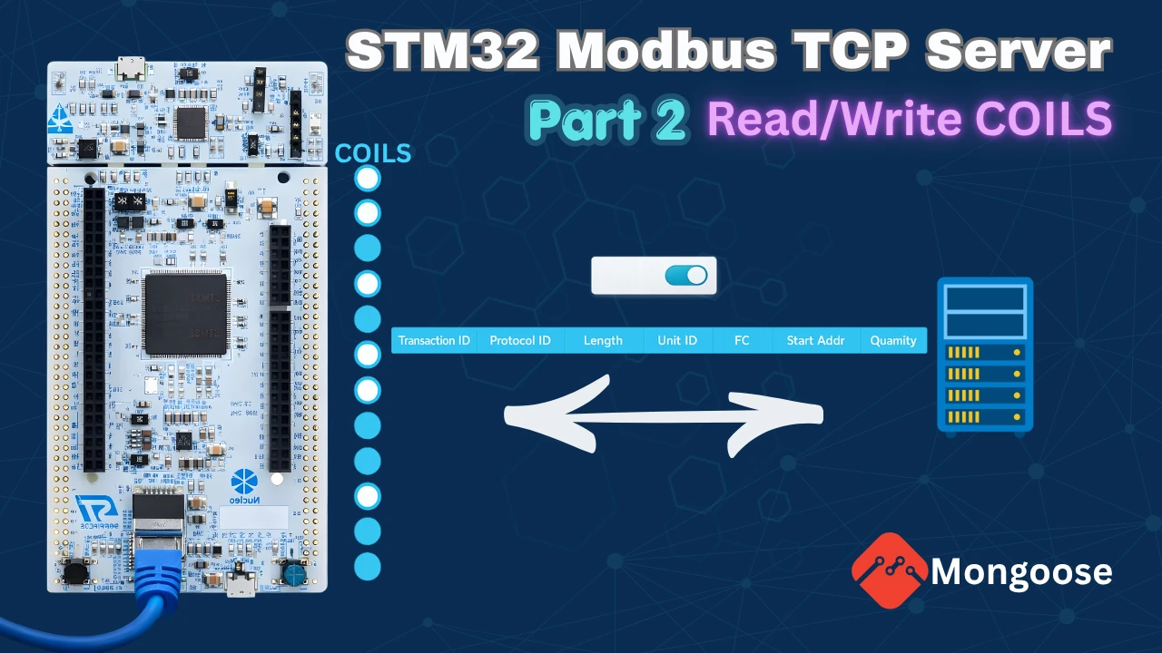
Modbus TCP Coils – How They Work on STM32
Before writing any code, it is worth understanding what makes coils different from the discrete inputs we covered in Part 1.
What Are Coils and Which Function Codes Do We Need
Coils are single-bit values — each one is either 0 or 1. Unlike discrete inputs which are read-only, coils can be both read and written by the Modbus client. They can also be modified by other sources — in our case, the Mongoose web UI.
There are three function codes involved in coil operations:
- Function Code 1 — Read coils. The client can request the status of one or more coils in a single request.
- Function Code 5 — Write a single coil. The client sends one address and one value.
- Function Code 15 — Write multiple coils. The client sends a starting address and an array of values.
We need to handle all three in the Modbus handler.
How the Coil Database Works
Since coils can be modified from two different sources — the Modbus client and the web UI — we need a shared place to store the current state of all coils. We use a small array called Coils_Data for this:
uint8_t Coils_Data[2] = {0x00, 0x00};Each coil occupies exactly one bit. With 10 coils, we need 10 bits, which fits in 2 bytes. Both READ_COIL and WRITE_COIL work against this database. Any change from the Modbus client or the web UI goes through these two functions, which keeps the state consistent across both sources.
How the Web UI Fits In
The Mongoose web UI uses a separate my_coils[] struct array to track coil states for the dashboard. The getter function reads from Coils_Data via READ_COIL before sending data to the browser. The setter function writes back to Coils_Data via WRITE_COIL after the user toggles a coil on the UI. This way, the Modbus client and the web UI always see the same state.

Coil Wiring and CubeMX Setup
Hardware Connections
In Part 1, we had 10 switches connected to the STM32 as inputs. For coils, we replace those switches with 10 LEDs. The LEDs are connected to the same pins, but now those pins are configured as outputs. The cathodes of all 10 LEDs are connected together and then connected to ground through a 330 ohm resistor to limit the current.
The image below shows the complete wiring for this setup.

CubeMX Configuration
We only need one change from the Part 1 CubeMX configuration — change all 10 pins from input to output and rename them from INPUT1–INPUT10 to COIL1–COIL10.
The image below shows the CubeMX GPIO configuration with all 10 coil pins set as outputs.

Everything else — Ethernet, UART, clock — stays exactly as it was in Part 1. Generate the code and let CubeIDE update the project.
Mongoose Web UI for Modbus TCP Coils
I have already covered how to create a new project using WebUI in the previous tutorial. We continue with the same project in the Mongoose wizard as well. Open the wizard and load the configuration file (mongoose_wizard.json) from the previous project. It is located inside the Mongoose folder of the CubeIDE project.
The wizard loads with the Part 1 configuration. Go to Settings → Directory and point it to the existing project folder. We will overwrite the previous wizard files instead of creating a new project.
Updating the Dashboard and API Endpoint
The only things that change in the wizard are the API endpoint name and the container label.
In the REST API section, rename the endpoint from inputs to coils. Since coils support both read and write, remove the read-only attribute that was set for inputs. The attribute level stays as is — each coil will be accessed as coils.level.
The image below shows the updated REST API endpoint for coils.

Go to the Page Container and make three changes:
- Change the container API variable from
inputstocoils - Replace the word “INPUT” with “COIL” in the text label — so the items read Coil 1 through Coil 10
- Set the toggle button API variable to
coils[i].level
The images below shows the updated container with coil labels and the correct API variable assignment.


Configuring WebSocket Updates
WebSocket is already enabled from Part 1. No changes are needed here.

Generate the project. The Mongoose files in the CubeIDE project folder will be updated. Open mongoose_glue.c and confirm it now references coils instead of inputs — both in the struct definition and the getter/setter function signatures.
The image below shows the updated mongoose_glue.c with coils struct and functions.

STM32 Modbus TCP Coil Code & Results
With the wizard files updated and CubeMX regenerated, we now move to main.c. We will comment out all the input-related code from Part 1 and write the coil implementation from scratch.
Coil Database, READ_COIL and WRITE_COIL Functions
First, define the Coils_Data array and the coil pin lookup structure:
uint8_t Coils_Data[2] = {0x00, 0x00};

typedef struct {
    GPIO_TypeDef *port;
    uint16_t pin;
} coil_t;

coil_t coils[] = {
    {COIL1_GPIO_Port,  COIL1_Pin},
    {COIL2_GPIO_Port,  COIL2_Pin},
    {COIL3_GPIO_Port,  COIL3_Pin},
    {COIL4_GPIO_Port,  COIL4_Pin},
    {COIL5_GPIO_Port,  COIL5_Pin},
    {COIL6_GPIO_Port,  COIL6_Pin},
    {COIL7_GPIO_Port,  COIL7_Pin},
    {COIL8_GPIO_Port,  COIL8_Pin},
    {COIL9_GPIO_Port,  COIL9_Pin},
    {COIL10_GPIO_Port, COIL10_Pin},
};Now write the READ_COIL function. It takes a coil index, finds which byte and bit it belongs to inside Coils_Data, and returns that bit:
bool READ_COIL(uint16_t i)
{
uint16_t startByte = i / 8;
uint8_t bitPosition = i % 8;
return (Coils_Data[startByte] >> bitPosition) & 0x01;
}For example, coil index 12 (coil 13) is in byte 1 (12/8 = 1) at bit position 4 (12%8 = 4).
The WRITE_COIL function works the same way but also updates the physical LED pin:
void WRITE_COIL(uint16_t i, bool val)
{
uint16_t startByte = i / 8;
uint8_t bitPosition = i % 8;
if (val == true) Coils_Data[startByte] |= (1 << bitPosition);
else Coils_Data[startByte] &= ~(1 << bitPosition);
HAL_GPIO_WritePin(coils[i].port, coils[i].pin, val);
}WRITE_COIL does two things: it updates the bit in Coils_Data, and it immediately drives the GPIO pin to match. So whatever calls WRITE_COIL — whether it is the Modbus handler or the web UI setter — both the database and the LED always stay in sync.
The Modbus Handler
Copy the handler from mongoose_glue.c, paste it into main.c, and rename it from glue_modbus_handler to my_modbus_handler to avoid a multiple definition conflict. Then remove the default read/write coil logic inside it and replace it with calls to our own functions:
void my_modbus_handler(struct mg_modbus_req *req)
{
if (req->func == MG_MODBUS_FUNC_READ_COILS) {
for (uint16_t i = 0; i < req->len; i++) {
req->u.bits[i] = READ_COIL(req->addr + i);
}
}
else if (req->func == MG_MODBUS_FUNC_WRITE_SINGLE_COIL) {
WRITE_COIL(req->addr, req->u.bits[0]);
}
else if (req->func == MG_MODBUS_FUNC_WRITE_MULTIPLE_COILS) {
for (uint16_t i = 0; i < req->len; i++) {
WRITE_COIL(req->addr + i, req->u.bits[i]);
}
}
else {
req->error = MG_MODBUS_ERR_DEVICE_FAILURE;
}
}The handler checks which function code the client sent and routes accordingly:
- FC1 — reads
req->lencoils starting fromreq->addrusingREAD_COILand fills the bits array - FC5 — writes one coil at
req->addrwith the first element of the bits array (bits[0]) - FC15 — writes multiple coils in a loop starting from
req->addr
Any unrecognised function code returns a device failure error.
Web UI Getter and Setter Functions
The web UI uses the struct coils type generated by the wizard. We need a renamed version of the struct for our array to avoid a conflict with the name already used in mongoose_glue.c. Hence I have changed it from s_coils[] to my_coils[].
Define the my_coils[] array with 10 elements, all initialised to false:
static struct coils my_coils[] = {
{false},{false},{false},{false},{false},
{false},{false},{false},{false},{false},
};The getter is called by the web UI whenever it needs the current state of all coils. Before returning the data to the web UI, we sync my_coils[] from Coils_Data using the function READ_COIL:
bool my_get_coils(struct coils *data, size_t i)
{
size_t array_size = sizeof(my_coils) / sizeof(my_coils[0]);
if (i >= array_size) return false;
for (int j = 0; j < array_size; j++) {
my_coils[j].level = READ_COIL(j);
}
*data = my_coils[i];
return true;
}The setter is called when the user toggles a coil on the web UI. It updates the my_coils[] array with the incoming data. We will then update the Coils_Data and the GPIO pin by calling the function WRITE_COIL:
void my_set_coils(struct coils *data, size_t i)
{
size_t array_size = sizeof(my_coils) / sizeof(my_coils[0]);
if (i < array_size) my_coils[i] = *data;
for (int j = 0; j < array_size; j++) {
WRITE_COIL(j, my_coils[j].level);
}
}Using READ_COIL in the getter and WRITE_COIL in the setter means the web UI and the Modbus client always share the same Coils_Data as the source.
Registering Handlers in main()
Inside the main function, after mongoose_init(), register the modbus handler, the coils HTTP handlers, and the WebSocket reporter:
mongoose_init();
mongoose_set_modbus_handler(my_modbus_handler);
mongoose_set_http_handlers("coils", my_get_coils, my_set_coils);
mongoose_add_ws_reporter(200, "coils");The WebSocket reporter pushes coil data to the browser every 200 milliseconds, keeping the dashboard in sync with any changes made by the Modbus client.
Full Code
Here is the complete set of additions made to main.c:
#include "mongoose_glue.h"
/* ---- Coil Database ---- */
uint8_t Coils_Data[2] = {0x00, 0x00};

typedef struct {
    GPIO_TypeDef *port;
    uint16_t pin;
} coil_t;

coil_t coils[] = {
    {COIL1_GPIO_Port,  COIL1_Pin},
    {COIL2_GPIO_Port,  COIL2_Pin},
    {COIL3_GPIO_Port,  COIL3_Pin},
    {COIL4_GPIO_Port,  COIL4_Pin},
    {COIL5_GPIO_Port,  COIL5_Pin},
    {COIL6_GPIO_Port,  COIL6_Pin},
    {COIL7_GPIO_Port,  COIL7_Pin},
    {COIL8_GPIO_Port,  COIL8_Pin},
    {COIL9_GPIO_Port,  COIL9_Pin},
    {COIL10_GPIO_Port, COIL10_Pin},
};
/* ---- READ and WRITE COIL ---- */
bool READ_COIL(uint16_t i)
{
    uint16_t startByte  = i / 8;
    uint8_t  bitPosition = i % 8;
    return (Coils_Data[startByte] >> bitPosition) & 0x01;
}
void WRITE_COIL(uint16_t i, bool val)
{
    uint16_t startByte   = i / 8;
    uint8_t  bitPosition = i % 8;

    if (val == true)  Coils_Data[startByte] |=  (1 << bitPosition);
    else              Coils_Data[startByte] &= ~(1 << bitPosition);

    HAL_GPIO_WritePin(coils[i].port, coils[i].pin, val);
}
/* ---- Modbus Handler ---- */
void my_modbus_handler(struct mg_modbus_req *req)
{
    if (req->func == MG_MODBUS_FUNC_READ_COILS) {
        for (uint16_t i = 0; i < req->len; i++) {
            req->u.bits[i] = READ_COIL(req->addr + i);
        }
    }
    else if (req->func == MG_MODBUS_FUNC_WRITE_SINGLE_COIL) {
        WRITE_COIL(req->addr, req->u.bits[0]);
    }
    else if (req->func == MG_MODBUS_FUNC_WRITE_MULTIPLE_COILS) {
        for (uint16_t i = 0; i < req->len; i++) {
            WRITE_COIL(req->addr + i, req->u.bits[i]);
        }
    }
    else {
        req->error = MG_MODBUS_ERR_DEVICE_FAILURE;
    }
}
/* ---- Web UI Coil Array ---- */
static struct coils my_coils[] = {
    {false},{false},{false},{false},{false},
    {false},{false},{false},{false},{false},
};
/* ---- Coil Getter ---- */
bool my_get_coils(struct coils *data, size_t i)
{
    size_t array_size = sizeof(my_coils) / sizeof(my_coils[0]);
    if (i >= array_size) return false;

    for (int j = 0; j < array_size; j++) {
        my_coils[j].level = READ_COIL(j);
    }

    *data = my_coils[i];
    return true;
}
/* ---- Coil Setter ---- */
void my_set_coils(struct coils *data, size_t i)
{
    size_t array_size = sizeof(my_coils) / sizeof(my_coils[0]);
    if (i < array_size) my_coils[i] = *data;

    for (int j = 0; j < array_size; j++) {
        WRITE_COIL(j, my_coils[j].level);
    }
}
/* ---- Inside main() ---- */
mongoose_init();
mongoose_set_modbus_handler(my_modbus_handler);
mongoose_set_http_handlers("coils", my_get_coils, my_set_coils);
mongoose_add_ws_reporter(200, "coils");
for (;;) {
mongoose_poll();
}Output
Serial Console
After flashing, open the serial console. Mongoose will initialize and the board will receive an IP address via DHCP or prints the assigned static IP address.
The image below shows the serial console output after flashing with Mongoose initialized and the IP address assigned.

Modbus Client – Reading Coils (FC1)
Open the Modbus client and connect to the board’s IP on port 502. Set the starting address to 1, request 10 coils, and set the function code to 1.
The image below shows the Modbus client response for reading 10 coils — all reporting zero at startup.

All 10 coils report zero, which is correct since Coils_Data is initialised to 0x00.
Let us look at the raw request bytes.
Client Request (sent bytes):
| Field | Size | Value | Description |
|---|---|---|---|
| Transaction ID | 2 bytes | 0x0001 | Unique ID per transaction |
| Protocol ID | 2 bytes | 0x0000 | Fixed for Modbus TCP |
| Length | 2 bytes | 0x0006 | Remaining byte count |
| Slave ID | 1 byte | 0x0A | Server address |
| Function Code | 1 byte | 0x01 | Read Coils |
| Start Address | 2 bytes | 0x0000 | First input address |
| Quantity | 2 bytes | 0x000A | Number of coils (10) |
Server Response (received bytes):
| Field | Size | Value | Description |
|---|---|---|---|
| Transaction ID | 2 bytes | 0x0001 | Echoed from request |
| Protocol ID | 2 bytes | 0x0000 | Fixed for Modbus TCP |
| Length | 2 bytes | 0x0005 | Remaining byte count |
| Slave ID | 1 byte | 0x0A | Server address |
| Function Code | 1 byte | 0x01 | Read Coils |
| Byte Count | 1 byte | 0x02 | Number of data bytes |
| Coil Data | 2 bytes | 0x00, 0x00 | Current States of the coils |
The data for the 10 coils is packed into 2 bytes — 8 bits in the first byte and 2 bits in the second.
Modbus Client – Writing Multiple Coils (FC15)
Open a write window. Write to 10 coils starting from coil 1, using function code 15. Set coils 1, 3, 5, 7, and 9 to 1, leaving the rest at 0.
The image below shows the Modbus client sending a write multiple coils request, and the LEDs 1, 3, 5, 7, and 9 on the STM32 board are turned ON.


The LEDs respond immediately. The web UI dashboard also reflects the same state — the corresponding toggles switch on automatically.
Web UI – Toggling Coils from the Browser
Open the browser and load the dashboard using the board’s IP address.
The image below shows the Mongoose web UI dashboard with 10 coil toggle buttons, some in the on state.

If you toggle the coils from the dashboard, the changes will be reflected on the LEDs connected to STM32. You can also request the LED states from the client, and it will also show the updated data.
This confirms that both sources — the Modbus client and the web UI — are reading from and writing to the same Coils_Data database.
Modbus Client – Writing a Single Coil (FC5)
We can also write individual coils using function code 5. Select coil 6 and set it to 0. The LED turns off and the dashboard toggle updates.
The GIF below shows the Modbus client using FC5 to write a single coil.

Reading from a Non-Zero Starting Address
We can also write/request a range of coils starting from any position, not just coil 1. For example, request 6 coils starting from coil 5. The response returns only the state of coils 5 through 10. Similarly, we can write 6 coils starting from coil 5 without affecting coils 1 through 4.
The GIF below shows a read request starting from coil 5 and the response showing only that subset.

STM32 Modbus TCP Server – Read and Write Coils using Mongoose — Video Tutorial
This video covers the complete implementation of Modbus TCP coil operations on STM32 using Mongoose. We implement function codes 1, 5, and 15 to read and write 10 coils, use a bit-packed database to track coil states, and connect everything to a live Mongoose web UI dashboard.
STM32 Modbus TCP Coils — Frequently Asked Questions
Conclusion
In this tutorial, we implemented Modbus TCP coil read and write operations on an STM32 using Mongoose. We handled all three coil function codes — FC1 for reading, FC5 for writing a single coil, and FC15 for writing multiple coils. We also added a Mongoose web UI that reads and updates the same coil states, giving us two independent ways to interact with the coils simultaneously.
The key design here is the Coils_Data byte array acting as the shared database. Both READ_COIL and WRITE_COIL operate on it, and both the Modbus handler and the web UI use the same two functions. This keeps the state consistent no matter which source makes a change.
In the next part of this series, we will work with holding registers — which allow the client to read and write 16-bit values instead of single bits.
Download STM32 Modbus TCP Coils Project Files
Complete CubeIDE project with Modbus TCP coil read/write support, Mongoose web UI dashboard, and 10-coil LED demo on STM32H755 Nucleo. Free to download — support the work if it helped you.
Browse More STM32 Modbus TCP Tutorials
STM32 LWIP Modbus TCP Tutorial: Server Setup (Part 1)
STM32 Modbus TCP (Part 2): Read Holding & Input Registers
STM32 Modbus TCP Server using LWIP – Part 3: Writing Holding Registers (FC06 & FC16)
STM32 Modbus TCP Server using LWIP – Part 4: Reading Coils and Discrete Inputs (FC01 & FC02)
STM32 Modbus TCP Server using LWIP – Part 5: Writing Coils (FC05 & FC15)

Subscribe
Login
0 Comments
Newest

