
Home ▸ STM32 Tutorials ▸ Modbus ▸ TCP ▸
Updated On: August 26, 2026
STM32 Modbus TCP Server – Read and Write Holding Registers using Mongoose
This is Part 3 of the STM32 Modbus TCP Server series. In the previous parts, we configured the STM32 as a Modbus TCP server and handled discrete inputs and coils. Now we move on to holding registers — one of the most commonly used data types in Modbus applications.
The STM32 is still acting as the server. This time, the Modbus client will be able to read and write holding registers using three function codes. We will also hook the registers up to the Mongoose Web UI, so values can be viewed and updated directly from a browser.
Other parts of the STM32 Modbus TCP series:
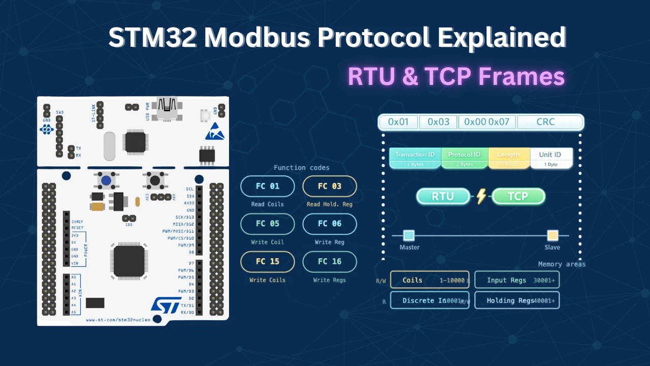
- Modbus TCP Protocol Explained
- Part 1 – STM32 Modbus TCP Server: Reading Discrete Inputs
- Part 2 – STM32 Modbus TCP Server: Read and Write Coils
- Part 3 – STM32 Modbus TCP Server: Read and Write Holding Registers
- Part 4 – STM32 Modbus TCP Server: Read Input Registers

What Are Holding Registers in Modbus?
Before we write any code, it helps to understand how holding registers differ from what we have covered so far.
What Are Holding Registers and Which Function Codes Do We Need
Holding registers are 16-bit read/write values. Unlike discrete inputs which are read-only single bits, holding registers can store any integer value up to 65535. They can be read and written by the Modbus client, and in our case, also updated through the Web UI.
There are three function codes we need to handle:
- Function Code 0x03 — Read holding registers. The client requests one or more registers in a single packet.
- Function Code 0x06 — Write a single register. The client provides one address and one value.
- Function Code 0x10 — Write multiple registers. The client provides a starting address and an array of values.
All three need to be handled inside the Modbus handler function.
How the Register Database Works
Since registers can be updated from both the Modbus client and the Web UI, we need a single shared database. I defined a 16-bit array with 12 elements for this:
uint16_t Holding_Reg_Data [12] = {1111,2222,3333,4444,5555,6666,
7777,8888,9999,1234,5678,9012};Every read and write operation — whether it comes from the Modbus client or the Web UI — goes through two functions: READ_Holding_REG and WRITE_Holding_REG. This ensures both sources always see the same data.
Working with holding registers is actually simpler than working with coils. Coils are single-bit values, so we had to calculate exact byte and bit positions to locate them. With registers, each register is its own 16-bit element in the array, so we can access it directly using the address as the index.
How the Web UI Fits In
The Mongoose Web UI uses a separate my_holding_registers[] struct array to track register values for the dashboard. The getter function reads from Holding_Reg_Data and copies the latest values into this struct before sending them to the browser. The setter function receives a new value from the browser and calls WRITE_Holding_REG to push it into the database. This keeps both the client and the UI in sync at all times.
Setting Up the Mongoose Web UI
We continue using the same Mongoose Web UI wizard from the previous parts of this series. We do not need to create a new project — we just need to update the existing one.
Loading the Previous Project in the Wizard
I have already covered how to create a new project using WebUI in the previous tutorial. We continue with the same project in the Mongoose wizard as well. Open the wizard and load the configuration file (mongoose_wizard.json) from the previous project. It is located inside the Mongoose folder of the CubeIDE project.
The wizard loads with the Part 2 configuration. Go to Settings → Directory and point it to the existing project folder. We will overwrite the previous wizard files instead of creating a new project.
Updating the REST API
First, go to the REST API section. We already have an endpoint from the coils project — that one was an array of Boolean values. Holding registers store 16-bit integers, so we need to make a few changes.

Rename the API endpoint from coils to holding_registers. Keep the type as array, but change the attribute name to value and set the type to integer. Set the default value to 0.
Updating the Page Content
Now go to Page Content. Change the container title from “Coils” to “Holding Registers”. Update the API variable of the main container from coils to holding_registers. Change the label text from “coil” to “register”.
Since holding registers start from address 40001, set the starting address in the UI to 40001. With 12 registers, the display will run from 40001 to 40012.


For the input element — holding registers store numeric values, so we do not need a toggle button. Use an input field instead. Set its API variable to holding_registers.value. Also enable the autosave on change option, so any value typed into the field is sent to the code automatically without needing a save button.


Configuring WebSocket Updates
WebSocket is already enabled from Part 2. No changes are needed here.

Generate the project. The Mongoose files in the CubeIDE project folder will be updated. Open mongoose_glue.c and confirm it now references holding_registers instead of coils — both in the struct definition and the getter/setter function signatures.
The image below shows the updated mongoose_glue.c with holding_registers struct and functions.

STM32 Code, Configuration and Testing
Now let’s import the project in CubeIDE and write the code.
Setting Up the Register Database in CubeIDE
Open main.c. First of all we will define the database array:
uint16_t Holding_Reg_Data [12] = {1111,2222,3333,4444,5555,6666,
7777,8888,9999,1234,5678,9012};This is our central database. All reads and writes will go through this array.
Writing the Modbus Handler
Go to mongoose_glue.c and copy the Modbus handler function. Paste it into main.c and rename it from glue_modbus_handler to my_modbus_handler to avoid naming conflicts with the original.
Now let’s define the two helper functions first.
READ_Holding_REG takes a register address and returns the corresponding value from the database:
uint16_t READ_Holding_REG(uint16_t i)
{
    return Holding_Reg_Data[i];
}WRITE_Holding_REG takes the register address and the new value and updates the database:
void WRITE_Holding_REG(uint16_t i, uint16_t val)
{
    Holding_Reg_Data[i] = val;
}Now let’s update the handler. The handler checks the function code and responds accordingly. For MG_MODBUS_FUNC_READ_HOLDING_REGISTER (FC 0x03), it loops through each requested register and stores the result in the regs pointer (not bits, since these are 16-bit values):
    for (uint16_t i = 0; i < req->len; i++) {
      req->u.regs[i] = READ_Holding_REG(req->addr + i);
}For MG_MODBUS_FUNC_WRITE_MULTIPLE_REGISTERS (FC 0x10), it loops through each register and calls the write function:
for (uint16_t i = 0; i < req->len; i++) {
WRITE_Holding_REG(req->addr + i, req->u.regs[i]);
}For MG_MODBUS_FUNC_WRITE_SINGLE_REGISTER (FC 0x06), there is no need for a loop. We just write the first element of the regs array:
WRITE_Holding_REG(req->addr, req->u.regs[0]);Here is the complete handler:
uint16_t READ_Holding_REG (uint16_t i)
{
return (Holding_Reg_Data[i]);
}
void WRITE_Holding_REG (uint16_t i, uint16_t val)
{
Holding_Reg_Data[i] = val;
}
void my_modbus_handler(struct mg_modbus_req *req)
{
if (req->func == MG_MODBUS_FUNC_READ_HOLDING_REGISTERS) {
    for (uint16_t i = 0; i < req->len; i++) {
      req->u.regs[i] = READ_Holding_REG(req->addr + i);
    }
}
else if (req->func == MG_MODBUS_FUNC_WRITE_MULTIPLE_REGISTERS) {
    for (uint16_t i = 0; i < req->len; i++) {
      WRITE_Holding_REG(req->addr + i, req->u.regs[i]);
    }
}
else if (req->func == MG_MODBUS_FUNC_WRITE_SINGLE_REGISTER) {
WRITE_Holding_REG(req->addr, req->u.regs[0]);
}
else {
req->error = MG_MODBUS_ERR_DEVICE_FAILURE;
}
}Getter and Setter Functions for the Web UI
Go back to mongoose_glue.c and copy the getter function, the setter function, and the register array. Paste them into main.c and rename everything to avoid conflicts with the originals.
Since we have 12 registers, define 12 elements in the local array and initialize them all to zero:
static struct holding_registers my_holding_registers[] = {
  {0},{0},{0},{0},{0},{0},{0},{0},{0},{0},{0},{0},
};The getter is called by the Web UI to fetch the current register values. Before copying data to the UI, we need to update the local array with the latest values from the database:
bool my_get_holding_registers(struct holding_registers *data, size_t i) {
  size_t array_size = sizeof(my_holding_registers) / sizeof(my_holding_registers[0]);
  if (i >= array_size) return false;
  my_holding_registers[i].value = READ_Holding_REG(i);  // ADD This Line
  *data = my_holding_registers[i];
  return true;
}The setter is called by the Web UI when the user types a new value. After copying the new value into the local array, we push it to the database as well:
void my_set_holding_registers(struct holding_registers *data, size_t i) {
  size_t array_size = sizeof(my_holding_registers) / sizeof(my_holding_registers[0]);
  if (i < array_size) my_holding_registers[i] = *data;
  WRITE_Holding_REG(i, my_holding_registers[i].value);  // ADD This Line
}Registering the Handlers and Building the Project
Inside the main function, after mongoose_init(), register the modbus handler, the HTTP handlers, and the WebSocket reporter:
mongoose_init();
  mongoose_set_modbus_handler(my_modbus_handler);
  mongoose_set_http_handlers("holding_registers", my_get_holding_registers, my_set_holding_registers);
mongoose_add_ws_reporter(200, "holding_registers");The WebSocket reporter pushes registers data to the browser every 200 milliseconds, keeping the dashboard in sync with any changes made by the Modbus client.
Testing with the Modbus Client
Serial Console Logs
After flashing, open the serial console. Mongoose will initialize and the board will receive an IP address via DHCP or prints the assigned static IP address.
The image below shows the serial console output after flashing with Mongoose initialized and the IP address assigned.

Open that IP address in a browser. The Web UI should show 12 registers, from 40001 to 40012, all displaying the initial values we set in the database array.
The image below shows the Web UI displaying the holding registers with their initial values.

Modbus Client Reading Registers
Now open the Modbus client. I am using the Simply Modbus TCP client here. Enter the server IP address and port 502, then connect.
Set the starting address to 40001, the register count to 12, and the data type to 16-bit unsigned. Set the function code to 3 (read holding registers) and send the request.
The image below shows the Modbus client response with all 12 register values returned by the STM32 server.

The values returned match exactly what we defined in the database. Everything is working correctly.
Reading the Modbus TCP Frame
Let’s look at the actual bytes being sent and received by the modbus client.

Client Request (FC 03 — Read Holding Registers):
| Field | Bytes | Value | Description |
|---|---|---|---|
| Transaction ID | 2 | 0x0001 | First transaction |
| Protocol ID | 2 | 0x0000 | Always 0 for Modbus |
| Length | 2 | 0x0006 | 6 bytes follow |
| Unit ID | 1 | 0x0A | Slave ID set in client |
| Function Code | 1 | 0x03 | Read holding registers |
| Starting Address | 2 | 0x0000 | Register 40001 |
| Register Count | 2 | 0x000C | 12 registers |
Server Response (FC 03):
| Field | Bytes | Value | Description |
|---|---|---|---|
| Transaction ID | 2 | 0x0001 | Matches request |
| Protocol ID | 2 | 0x0000 | Fixed |
| Length | 2 | 0x001B | 27 bytes follow |
| Unit ID | 1 | 0x0A | Same as request |
| Function Code | 1 | 0x03 | Read holding registers |
| Byte Count | 1 | 0x18 | 24 data bytes |
| Register Data | 24 | — | 12 registers × 2 bytes each |
Each register is 16 bits, so 12 registers = 24 bytes of data.
Writing Registers from the Client
To write data, open the write window in the Modbus client. Let’s first write a single register — say we want to update register 40008 with a new value. With only one register being written, the client will automatically use function code 6.
The image below shows the client write response and the Web UI updating register 40008 with the new value.

The Web UI updates almost instantly because the WebSocket refreshes every 200 milliseconds.
Now let’s write multiple registers. I want to update four registers starting from address 40004. Enter the values and send the request — the function code will automatically change to 16 for multiple registers.
The image below shows registers 40004 through 40007 updated with new values after the write multiple request.

Let’s send a read request again to confirm. All the values returned by the server match what we wrote. Writing from the Modbus client is working correctly.
Writing Registers from the Web UI
Now let’s update some registers from the browser. I am going to change the values in registers 40001, 40002, 40003, and 40004. Just type the new value into the input field and press Enter — the autosave on change option takes care of sending it to the database immediately.
The image below shows updated values in the Web UI and the Modbus client confirming those changes via a read request.

After making the changes, send a read request from the Modbus client. The updated values come back in the response, which confirms the Web UI setter is writing to the database correctly.
STM32 Modbus TCP Server – Holding Registers using Mongoose — Video Tutorial
This video covers the complete implementation of Modbus TCP holding register operations on STM32 using the Mongoose library. We handle function codes 3, 6, and 16, build a shared register database, and connect a live Web UI to display and modify register values in real time.
STM32 Modbus TCP Holding Registers — Frequently Asked Questions
Conclusion
In this part, we configured the STM32 as a Modbus TCP server capable of handling all three holding register function codes — read (FC 03), write single (FC 06), and write multiple (FC 10). We built a shared database array that both the Modbus client and the Web UI write to, which keeps everything in sync without any extra logic.
The getter and setter functions act as the bridge between the Mongoose Web UI and the raw database, and the WebSocket reporter handles the live updates automatically every 200 milliseconds.
In the next part, we will move to input registers. We will also connect real hardware like an ADC, so the client can read live sensor values directly from the STM32.
Download STM32 Modbus TCP Server Holding Registers Project
Open source CubeMX project files and HAL source code, tested on real hardware. Free to use — support the work if it helped you.
Browse More STM32 Modbus TCP Tutorials
STM32 LWIP Modbus TCP Tutorial: Server Setup (Part 1)
STM32 Modbus TCP (Part 2): Read Holding & Input Registers
STM32 Modbus TCP Server using LWIP – Part 3: Writing Holding Registers (FC06 & FC16)
STM32 Modbus TCP Server using LWIP – Part 4: Reading Coils and Discrete Inputs (FC01 & FC02)
STM32 Modbus TCP Server using LWIP – Part 5: Writing Coils (FC05 & FC15)

Subscribe
Login
0 Comments
Newest

