
Home ▸ STM32 Tutorials ▸
Updated On: August 26, 2026
STM32 Modbus TCP Server – Read Input Registers and Control PWM Output
This is Part 4 of the STM32 Modbus TCP Server series. Here is a quick recap of what we have covered so far:
- Modbus TCP Protocol Explained
- Part 1 – STM32 Modbus TCP Server: Reading Discrete Inputs
- Part 2 – STM32 Modbus TCP Server: Read and Write Coils
- Part 3 – STM32 Modbus TCP Server: Holding Registers
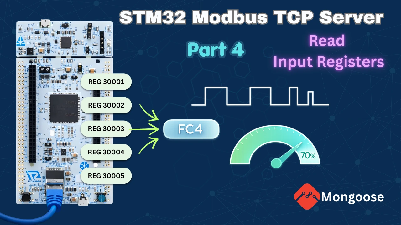
he STM32 is still acting as the server. This time, the Modbus client will be able to read input registers using function code 0x04. We will also hook the registers up to the Mongoose Web UI, so values can be viewed and updated directly from a browser.
In this part, we add two new things to the server. First, we implement input registers so a Modbus client can read a live ADC value from a potentiometer. Second, we extend the holding register support so that writing a value directly controls the brightness of an LED through PWM.
We continue building on the same Mongoose-based project from the previous parts.
What Are Input Registers in Modbus?
Before writing any code, it helps to understand what input registers are and how they differ from what we have already implemented.
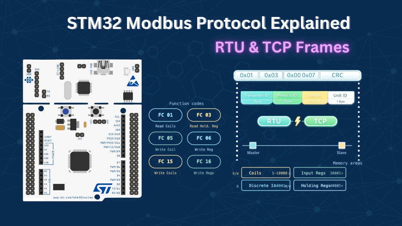
Input Registers vs Holding Registers
Holding registers are 16-bit read/write values stored in a software database. Both the Modbus client and the Web UI can read and write them freely. We covered this in Part 3. In Modbus terminology, these registers are typically referenced starting from 40001.
Input registers are different. They are also 16-bit values, but they are read-only and they represent hardware state — not a software database. Their values come directly from a hardware source like an ADC, a sensor, or a counter. Neither the Modbus client nor the Web UI can write to them. They can only read what the hardware is reporting. These registers are typically referenced starting from 30001.
In our case, the first input register at address 30001 will hold the live ADC reading from a potentiometer. The remaining five registers — 30002 to 30006 — will still use a software database since we only have one potentiometer connected, but the first register will always reflect the actual hardware value coming from the ADC peripheral.
Function Codes Used in This Tutorial
The table below shows the function codes we will use in this tutorial.
| Function Code | Hex | Operation |
|---|---|---|
| FC3 | 0x03 | Read holding registers |
| FC4 | 0x04 | Read input registers |
| FC6 | 0x06 | Write single holding register |
| FC16 | 0x10 | Write multiple holding registers |
Function code 4 is new in this part. It is the only way a Modbus client can request input register data from the server. The server must handle it separately in the Modbus handler.
Wiring – Potentiometer and LED on STM32
We need two hardware connections for this tutorial. Both pins — PC0 and PA3 — were previously configured as GPIO outputs for coils in Part 2, so we need to repurpose them.
Potentiometer on ADC1 Channel 10
I connected the potentiometer to pin PC0, which maps to ADC1 Channel 10 on the STM32H755 Nucleo board. The potentiometer is powered from the 3.3V pin on the board itself. The output pin will connect to PC0. Depending on the potentiometer position, the voltage at PC0 will range from 0 V to 3.3 V. The ADC is configured for 16-bit resolution, so the output values range from 0 to 65535.
The image below shows the potentiometer and LED connection to the STM32 Nucleo board.

LED on Timer 2 PWM Output
The LED is connected to pin PA3, which can be configured as Timer 2 Channel 4. We will use PWM to control the brightness. The Timer 2 counter period is set to 65535, which gives us a full 16-bit duty cycle range. A holding register value of 0 means 0% duty cycle (LED off), and 65535 means 100% duty cycle (full brightness). Since both the holding register and the capture compare register use the same 16-bit range, no scaling is needed.
Setting Up ADC, PWM, and Mongoose Wizard
CubeMX Configuration
We need to make three changes from the previous project in CubeMX.
First, disable the GPIO output configurations for pins PC0 and PA3. These were coil output pins in Part 2 and need to be freed up.

Next, configure PC0 as ADC1 Channel 10. Go to ADC1 in the peripheral list, enable Channel 10 in single-ended mode, and leave the resolution at 16-bit (the default).

Then configure PA3 as Timer 2 Channel 4 in PWM Generation mode. Open TIM2 settings, enable Channel 4 as PWM Generation, and set the Counter Period to 65535. This gives the full 16-bit range for the duty cycle.

Generate the code from CubeMX and let CubeIDE update the project.
Loading the Previous Project in the Mongoose Wizard
We continue using the same Mongoose Web UI wizard from the previous parts of this series. We do not need to create a new project — we just need to update the existing one.
I have already covered how to create a new project using WebUI in the previous tutorial. We continue with the same project in the Mongoose wizard as well. Open the wizard and load the configuration file (mongoose_wizard.json) from the previous project. It is located inside the Mongoose folder of the CubeIDE project.
The wizard loads with the Part 3 configuration. Go to Settings → Directory and point it to the existing project folder. We will overwrite the previous wizard files instead of creating a new project.
Adding the Input Registers Container in Mongoose Wizard
Go to Page Content. The holding registers container is already there from Part 3. We need to add a new container for input registers right next to it.
The easiest way to do this is to copy the existing holding registers container and paste it next to it. This saves time since the structure is similar — we just need to update the labels and API variables.
The image below shows the Page Content section with the copied container placed next to the holding registers container.

Rename the label at the top of the new container from “Holding Registers” to “Input Registers”. Change the starting address in the label to 30001, since input registers begin at Modbus address 30001.
The image below shows the input registers container with the updated label and starting address.

Updating the REST API for Input Registers
Go to the REST API section. The holding registers endpoint is already there. We need to add a new endpoint for input registers.
Click to add a new endpoint and configure it as follows:
- Name:
input_registers - Type: Array
- Mark it as Read-Only — input registers cannot be written from either the client or the Web UI
- Add one attribute: name it
value, set the type to Integer, and initialize it to0
The image below shows the new input_registers REST API endpoint configured as read-only with an integer value attribute.

Configuring the Page Content
Go back to Page Content and update the input registers container we created earlier.
Click on the text element inside the container and update it to use the input_registers API variable. The register address label should already show 30001 from the earlier step.
Click on the input field element and change its API variable from holding_registers[i].value to input_registers[i].value.
The images below shows the completed input registers container in the Page Content section with the correct API variable assigned.


Configuring WebSocket Updates
WebSocket is already enabled from Part 2. No changes are needed here.

Click Generate Code. The Mongoose folder in the CubeIDE project will be updated. Open mongoose_glue.c and confirm that the input register struct and getter function have been generated alongside the existing holding register functions.
The image below shows the updated mongoose_glue.c with both holding registers and input registers structs and function signatures.

Input Register Code and Testing
With the wizard files updated and CubeMX regenerated, let’s move to main.c and write the code.
ADC and Input Register Functions
First, let’s define the ADC read function. This starts the ADC in polling mode, waits for the conversion to complete, reads the value, and returns it.
uint16_t ReadADC(void)
{
    HAL_ADC_Start(&hadc1);
    HAL_ADC_PollForConversion(&hadc1, 100);
    uint16_t adcVal = HAL_ADC_GetValue(&hadc1);
    HAL_ADC_Stop(&hadc1);
    return adcVal;
}Next, define the input register database. I am going to use 6 input registers. The first one will always return the live ADC value, so its initial value in the array does not really matter — it gets overwritten every time. The remaining five use the database values directly.
uint16_t Input_Reg_Data[6] = {0, 2222, 3333, 4444, 5555, 6666};The READ_Input_REG function handles the routing. If register 0 is requested, it calls ReadADC() and returns the live hardware value. For all other registers, it returns from the database.
uint16_t READ_Input_REG(uint16_t i)
{
if (i == 0)
{
return ReadADC();
}
return Input_Reg_Data[i];
}This approach is consistent with how READ_Holding_REG works in Part 3 — a single function that abstracts away where the data comes from.
Getter Function for the Web UI
Copy the input register struct array and getter function skeleton from mongoose_glue.c and paste them into main.c. Rename the array to my_input_registers to avoid a naming conflict with the original definition in the glue file.
Define 6 elements in the array since we have 6 input registers:
static struct input_registers my_input_registers[] = {
{0}, {0}, {0}, {0}, {0}, {0},
};The getter function is called by the Web UI every time it wants to refresh the input register display. Before copying data to the UI, we need to fetch the latest value from READ_Input_REG. For register 0 that means calling the ReadADC(). For the rest, it pulls from the database.
bool my_get_input_registers(struct input_registers *data, size_t i)
{
size_t array_size = sizeof(my_input_registers) / sizeof(my_input_registers[0]);
if (i >= array_size) return false;
my_input_registers[i].value = READ_Input_REG(i); // Fetch latest value
*data = my_input_registers[i];
return true;
}Since input registers are read-only, there is no setter function. We will pass NULL when registering the handler.
Extending the Modbus Handler for FC4
In Part 3, we defined my_modbus_handler to handle FC3, FC6, and FC16. We now need to add a condition for FC4 — read input registers.
Inside the handler, add one more else if block:
else if (req->func == MG_MODBUS_FUNC_READ_INPUT_REGISTERS) {
for (uint16_t i = 0; i < req->len; i++) {
req->u.regs[i] = READ_Input_REG(req->addr + i);
}
}This loops through the requested registers and fills the response buffer by calling READ_Input_REG for each address. Everything else — including the ADC call for register 0 — is handled inside that function.
Connecting PWM to the Holding Register
The holding registers from Part 3 are already in place. We only need to add one thing: when the first holding register (index 0) is written, we want to update the PWM duty cycle.
Inside WRITE_Holding_REG, add a check for index 0 and write the value directly to Timer 2’s Capture Compare Register 4:
void WRITE_Holding_REG(uint16_t i, uint16_t val)
{
if (i == 0)
{
TIM2->CCR4 = val;
}
Holding_Reg_Data[i] = val;
}Since the holding register and TIM2->CCR4 both accept a 16-bit value in the same range (0–65535), no conversion or scaling is needed. We also initialize the first holding register to 0 so the LED starts in the off state:
uint16_t Holding_Reg_Data[12] = {0, 2222, 3333, 4444, 5555, 6666, 7777, 8888, 9999, 1234, 5678, 9012};Registering the Handlers in Main
In main(), before calling mongoose_init(), start the PWM output:
HAL_TIM_PWM_Start(&htim2, TIM_CHANNEL_4);After mongoose_init(), register all the handlers. The Modbus handler, holding register getter and setter are already in place from Part 3. Add the input register handler and its WebSocket reporter:
mongoose_init();
mongoose_set_modbus_handler(my_modbus_handler);
mongoose_set_http_handlers("holding_registers", my_get_holding_registers, my_set_holding_registers);
mongoose_set_http_handlers("input_registers", my_get_input_registers, NULL);
mongoose_add_ws_reporter(200, "holding_registers");
mongoose_add_ws_reporter(200, "input_registers");Note that NULL is passed in place of the setter for input registers — no setter exists since they are read-only. The WebSocket reporter for both register types will push updates to the browser every 200 milliseconds.
Full Combined Code
Here is the complete code combining everything from this part:
/*************** HOLDING REGISTERS *********************/
uint16_t Holding_Reg_Data[12] = {0, 2222, 3333, 4444, 5555, 6666,
7777, 8888, 9999, 1234, 5678, 9012};
uint16_t READ_Holding_REG(uint16_t i)
{
return Holding_Reg_Data[i];
}
void WRITE_Holding_REG(uint16_t i, uint16_t val)
{
if (i == 0)
{
TIM2->CCR4 = val;
}
Holding_Reg_Data[i] = val;
}
static struct holding_registers my_holding_registers[] = {
{0},{0},{0},{0},{0},{0},{0},{0},{0},{0},{0},{0},
};
bool my_get_holding_registers(struct holding_registers *data, size_t i)
{
size_t array_size = sizeof(my_holding_registers) / sizeof(my_holding_registers[0]);
if (i >= array_size) return false;
my_holding_registers[i].value = READ_Holding_REG(i);
*data = my_holding_registers[i];
return true;
}
void my_set_holding_registers(struct holding_registers *data, size_t i)
{
size_t array_size = sizeof(my_holding_registers) / sizeof(my_holding_registers[0]);
if (i < array_size) my_holding_registers[i] = *data;
WRITE_Holding_REG(i, my_holding_registers[i].value);
}
/*************** INPUT REGISTERS *********************/
uint16_t ReadADC(void)
{
    HAL_ADC_Start(&hadc1);
    HAL_ADC_PollForConversion(&hadc1, 100);
    uint16_t adcVal = HAL_ADC_GetValue(&hadc1);
    HAL_ADC_Stop(&hadc1);
    return adcVal;
}
uint16_t Input_Reg_Data[6] = {0, 2222, 3333, 4444, 5555, 6666};
uint16_t READ_Input_REG(uint16_t i)
{
    if (i == 0)
    {
        return ReadADC();
    }
    return Input_Reg_Data[i];
}
static struct input_registers my_input_registers[] = {
    {0}, {0}, {0}, {0}, {0}, {0},
};
bool my_get_input_registers(struct input_registers *data, size_t i)
{
size_t array_size = sizeof(my_input_registers) / sizeof(my_input_registers[0]);
if (i >= array_size) return false;
my_input_registers[i].value = READ_Input_REG(i);
*data = my_input_registers[i];
return true;
}
/*************** MODBUS HANDLER *********************/
void my_modbus_handler(struct mg_modbus_req *req)
{
if (req->func == MG_MODBUS_FUNC_READ_HOLDING_REGISTERS) {
for (uint16_t i = 0; i < req->len; i++) {
req->u.regs[i] = READ_Holding_REG(req->addr + i);
}
}
else if (req->func == MG_MODBUS_FUNC_WRITE_MULTIPLE_REGISTERS) {
for (uint16_t i = 0; i < req->len; i++) {
WRITE_Holding_REG(req->addr + i, req->u.regs[i]);
}
}
else if (req->func == MG_MODBUS_FUNC_WRITE_SINGLE_REGISTER) {
WRITE_Holding_REG(req->addr, req->u.regs[0]);
}
else if (req->func == MG_MODBUS_FUNC_READ_INPUT_REGISTERS) {
    for (uint16_t i = 0; i < req->len; i++) {
        req->u.regs[i] = READ_Input_REG(req->addr + i);
    }
}
else {
req->error = MG_MODBUS_ERR_DEVICE_FAILURE;
}
}
/*************** MAIN *********************/
int main(void)
{
HAL_Init();
SystemClock_Config();
PeriphCommonClock_Config();
MX_GPIO_Init();
MX_ETH_Init();
MX_RNG_Init();
MX_USART3_UART_Init();
MX_ADC1_Init();
MX_TIM2_Init();
HAL_TIM_PWM_Start(&htim2, TIM_CHANNEL_4);
mongoose_init();
mongoose_set_modbus_handler(my_modbus_handler);
mongoose_set_http_handlers("holding_registers", my_get_holding_registers, my_set_holding_registers);
mongoose_set_http_handlers("input_registers", my_get_input_registers, NULL);
mongoose_add_ws_reporter(200, "holding_registers");
mongoose_add_ws_reporter(200, "input_registers");
for (;;) {
mongoose_poll();
}
}
Note on build errors:
After adding ADC in CubeMX, you may get around 22 build errors related to HAL ADC functions. This is a known CubeIDE issue — the ADC HAL source files are not automatically added to the build path. To fix it, navigate to Drivers > STM32H7xx_HAL_Driver > Src in the project, find the ADC source files, and copy them into your project’s HAL Drivers Src folder. The project should build cleanly after that.
Testing with Web UI
Flash the project to the board and open the serial console. Mongoose will initialize and print the IP address — either a static IP if you configured one, or a DHCP-assigned address.
The image below shows the serial console output with Mongoose initialized and the IP address assigned.

Open the IP address in a browser. The Web UI will show all 12 holding registers and 6 input registers. The first input register will be continuously changing — that is the live ADC reading from the potentiometer.
The image below shows the Web UI dashboard with both holding and input registers, with the first input register updating live from the potentiometer.

Turn the potentiometer. The value of the first input register changes accordingly. At maximum position it should reach 65535. Rotate it back and the value decreases. The other five input registers will hold the fixed database values.
Now test the LED. The first holding register starts at 0, so the LED is off. Type a value into the first holding register field in the Web UI and press Enter. The LED turns on at a brightness proportional to the value you entered. At 65535 it reaches full brightness.
The image below shows the LED brightness changing as the holding register value is updated through the Web UI.


Testing with Modbus Client
I am going to use Simply Modbus TCP Client software on the computer to act as a client. First we need to Connect the client to the server’s IP (192.168.0.10) address on port 502.
Modbus Client — Reading Input Registers (FC4)
Set the starting address to 30001 and request 6 registers. The software automatically sets the function code to 4. Click Send.
All 6 register values are returned. If the first value appears as a negative number, that is because the display type is set to signed 16-bit integer. Change it to unsigned 16-bit and the correct value will appear — it should match what the Web UI is showing.
The image below shows the Simply Modbus TCP client with the FC4 response data for all 6 input registers.

Reading the Modbus TCP Frame
Let’s look at the actual bytes being sent and received by the modbus client.

Client Request (FC4 — Read Input Registers):
| Field | Bytes | Value | Description |
|---|---|---|---|
| Transaction ID | 2 | 0x0001 | First transaction |
| Protocol ID | 2 | 0x0000 | Always 0 for Modbus |
| Length | 2 | 0x0006 | 6 bytes follow |
| Unit ID | 1 | 0x0A | Slave ID set in client |
| Function Code | 1 | 0x04 | Read input registers |
| Starting Address | 2 | 0x0000 | Register 30001 (address offset is 0) |
| Register Count | 2 | 0x0006 | 6 registers |
Server Response (FC4):
| Field | Bytes | Value | Description |
|---|---|---|---|
| Transaction ID | 2 | 0x0001 | Matches request |
| Protocol ID | 2 | 0x0000 | Fixed |
| Length | 2 | 0x000F | 15 bytes follow |
| Unit ID | 1 | 0x0A | Same as request |
| Function Code | 1 | 0x04 | Read input registers |
| Byte Count | 1 | 0x0C | 12 data bytes (6 × 2 bytes) |
| Register Data | 12 | — | 6 registers × 2 bytes each |
Modbus Client — Writing Holding Registers (FC6)
Switch to the Write tab in the Modbus client. Write to address 40001 with function code 6. Write the value 0 — the LED turns off and the Web UI updates to show 0 in the first holding register. Write 20000 — the LED comes on at moderate brightness. Write 65535 — full brightness.
The image below shows the Modbus client writing to holding register 40001 with the LED responding in real time.


The LED responds instantly because WRITE_Holding_REG updates TIM2->CCR4 directly on every write. No polling or delay is involved.
STM32 Modbus TCP Server – Input Registers & PWM — Video Tutorial
This video walks through adding input register and PWM support to the STM32 Modbus TCP server using Mongoose. We configure the ADC and Timer 2 in CubeMX, update the Mongoose Wizard for a second register container, and test everything with both the Web UI and a Modbus TCP client.
Frequently Asked Questions
Conclusion
In this part, we added input register support to the STM32 Modbus TCP server. We connected a potentiometer to the ADC and fed the live hardware value directly into the first input register. A Modbus client can now read this value at any time using function code 4 — and the Web UI displays it in real time through the WebSocket reporter.
We also extended the holding register implementation from Part 3 by connecting register 0 to Timer 2's PWM output. Writing any value between 0 and 65535 now directly changes the LED brightness — no scaling, no conversion needed.
Between Parts 1 and 4, the STM32 Modbus TCP server now handles all four main Modbus data types — discrete inputs, coils, holding registers, and input registers — all running through the Mongoose networking library with a live Web UI on top.
In the next part, we flip the setup. Instead of the STM32 acting as a server that waits for requests, we will configure it as a Modbus TCP client. The STM32 will be the one initiating requests and reading data from another server — which is exactly how most real industrial systems work.
Download STM32 Modbus TCP Server Input Registers Project
Open source CubeMX project files and HAL source code, tested on real hardware. Free to use — support the work if it helped you.
Browse More STM32 Modbus TCP Tutorials
STM32 LWIP Modbus TCP Tutorial: Server Setup (Part 1)
STM32 Modbus TCP (Part 2): Read Holding & Input Registers
STM32 Modbus TCP Server using LWIP – Part 3: Writing Holding Registers (FC06 & FC16)
STM32 Modbus TCP Server using LWIP – Part 4: Reading Coils and Discrete Inputs (FC01 & FC02)
STM32 Modbus TCP Server using LWIP – Part 5: Writing Coils (FC05 & FC15)

Subscribe
Login
0 Comments
Newest

