
Home ▸ STM32 Tutorials ▸
Updated On: May 21, 2026
STM32 Blink LED — First Project with CubeMX and CubeIDE
This is the first tutorial in the STM32 beginner series. We start from zero — no existing project, no pre-configured template.
I will walk through the complete process of creating a new project in STM32CubeMX, configuring the system clock for different STM32 development boards, setting up a GPIO pin as output, and writing the HAL code to blink an LED. We will also cover how to build and flash the project to the board directly from STM32CubeIDE.
I am using the Nucleo-F446RE throughout this tutorial. The steps are the same for the Blue Pill (F103C8), Discovery F407, and Nucleo-144 boards — with one key difference in the clock configuration, which I will explain in detail so you can follow along on whichever board you have.

How STM32 LED Blink Works
Before we jump into CubeMX, let us understand the overall flow of what we are doing. We need to create a new project, configure the system clock so the MCU runs at the correct speed, enable a GPIO pin as output, and then write code that toggles that pin with a delay. Each step builds on the previous one, so it is worth getting them right.
Selecting the MCU in CubeMX
Since STM32CubeIDE no longer bundles the configuration tool directly, we use STM32CubeMX separately to set up the project.
When CubeMX opens, we have two options: select a development board, or directly select the MCU. I prefer selecting the MCU directly. This gives us full control over every pin and peripheral from the beginning, rather than starting from a pre-set board configuration.
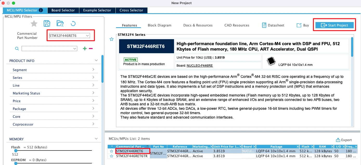
Type the name of your microcontroller in the search box. I am using the STM32F446RET6, which is the MCU on the Nucleo-F446RE board. Select it from the list and click Start Project to open the configuration tool.
The image below shows the STM32CubeMX MCU selector with the STM32F446RET6 selected.
Understanding HSE Clock Sources on STM32 Boards
This is the step where most beginners get confused, and it causes a lot of issues. Before we configure the clock in CubeMX, we need to understand what crystal options are physically available on the board we are using.
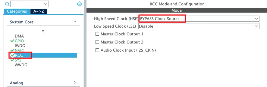
Go to the RCC tab in CubeMX. Here we select the clock source for the system. The two options are:
- HSE (High-Speed External) — an external crystal connected to the MCU.
- LSE (Low-Speed External) — a 32 kHz crystal, mainly used for the RTC peripheral.
The question is: what HSE source do we actually have on our board?
Let me walk through the most common STM32 boards.
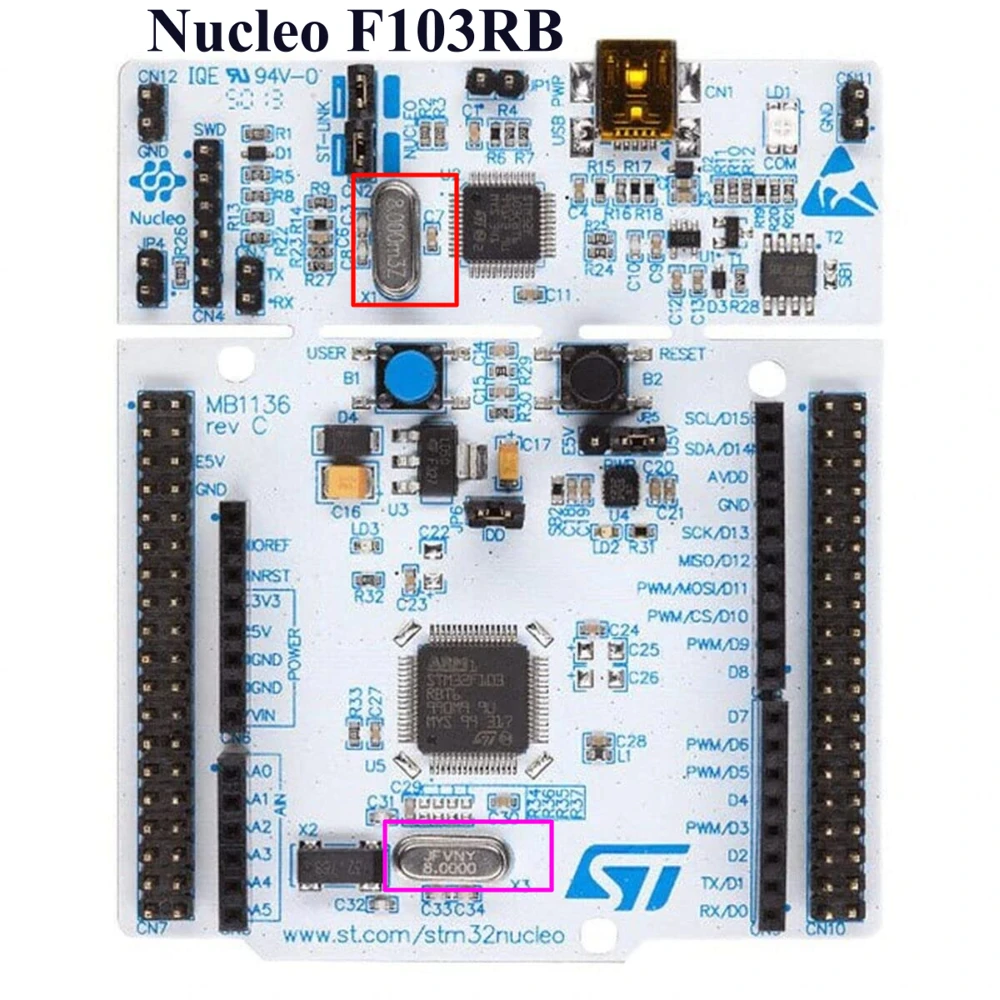
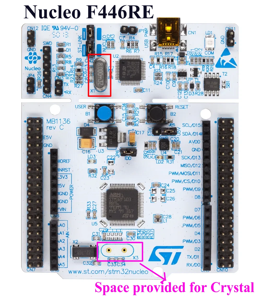
Nucleo-F103RB and Nucleo-F446RE
Both boards have an 8 MHz crystal on the ST-Link section of the board. On the F103, there is also a separate crystal connected directly to the MCU. On the F446RE however, that MCU-side crystal is missing. Even so, we can still use the ST-Link crystal as a clock source by selecting Bypass Clock Source instead of Crystal/Ceramic Resonator.
In Bypass mode, the MCU does not drive an external oscillator. Instead, it accepts a pre-generated clock signal directly from the ST-Link chip. This is the correct option for the Nucleo-F446.
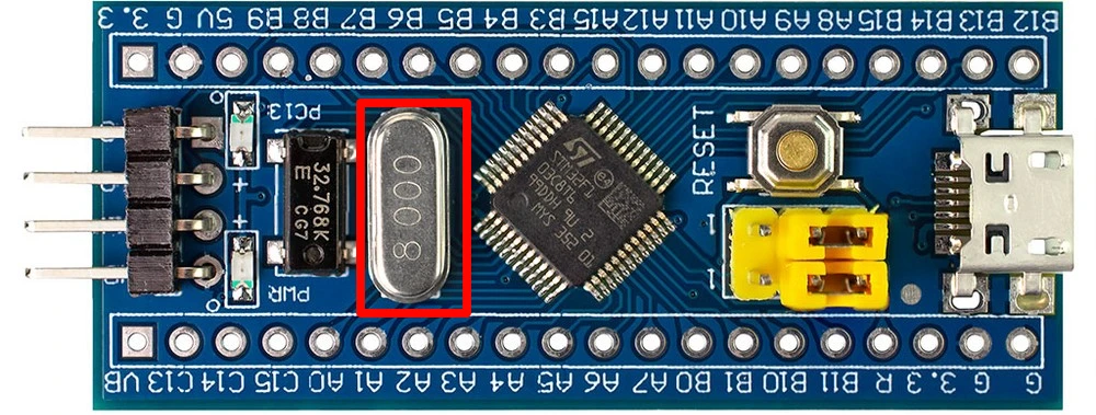
Blue Pill (STM32F103C8)
This board has an 8 MHz crystal connected directly to the MCU, plus a 32 kHz crystal for the RTC. So we can use Crystal/Ceramic Resonator as the HSE source.
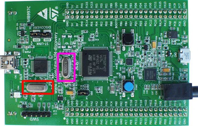
Discovery F407
The ST-Link section has its own 8 MHz crystal, and the MCU also has a separate 8 MHz crystal connected to it. Select Crystal/Ceramic Resonator for this board.
Nucleo-144 (e.g., H753)
This board has three crystals: X1 (25 MHz on the ST-Link section), X3 (32 kHz for the RTC) and X2 (not connected by default, pads available for a 25 MHz crystal). Since X3 is not connected, we again select Bypass Clock Source and use the ST-Link clock.
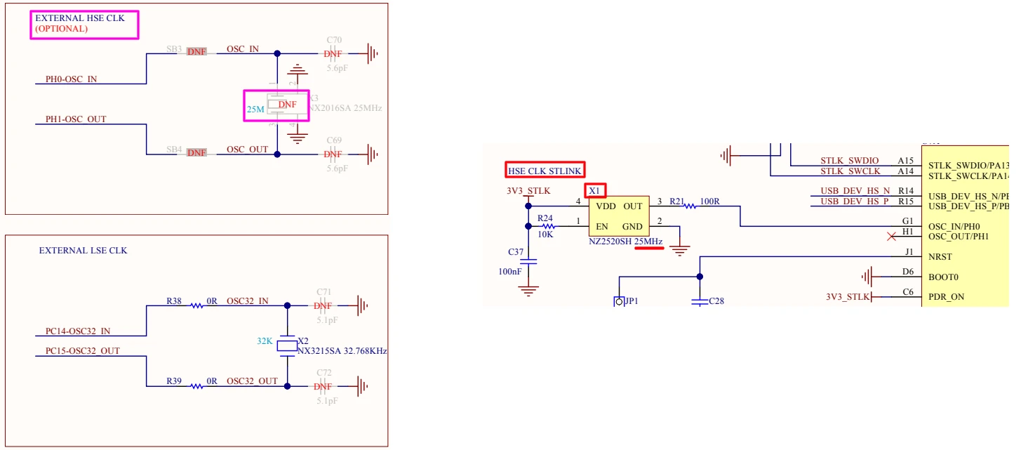
The rule is simple: if your board has a crystal physically connected to the MCU’s HSE pins, choose Crystal/Ceramic Resonator. If not, choose Bypass Clock Source and use the ST-Link oscillator.
Configuring the System Clock
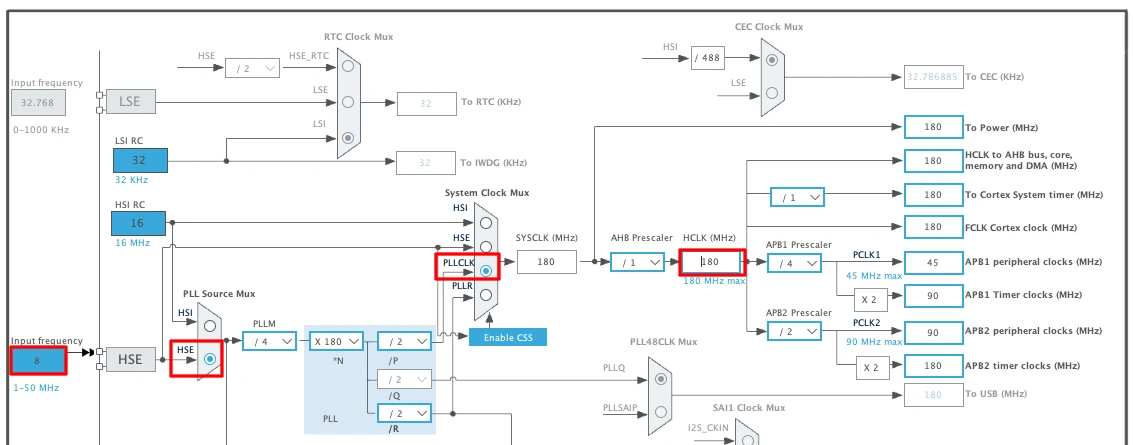
With the HSE source selected, we move to the Clock Configuration tab. This is the main clock tree, and we configure it from left to right.
Here is what we need to set:
- Select HSE as the clock input source.
- Enter the crystal frequency — 8 MHz for most Nucleo and Blue Pill boards.
- Select PLLCLK as the system clock source.
- Enter the target system clock frequency — for the F446, the maximum is 180 MHz.
Once we enter 180 MHz and press Enter, CubeMX automatically calculates the required PLL multipliers and dividers. We do not need to set those manually.
Wiring & GPIO Configuration
The wiring for an LED blink project is minimal — we are using the onboard LED, so there is nothing to connect externally. But we still need to identify the correct pin and configure it properly.
Finding the LED Pin on Your Board
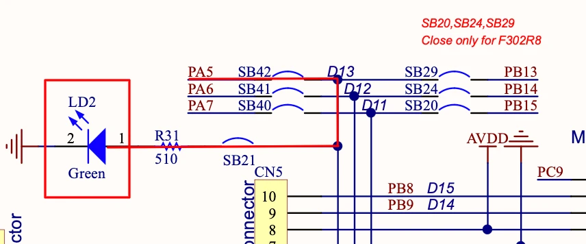
The Nucleo-F446RE has one onboard LED. Looking at the board schematic, we can see that a green LED is connected to pin PA5, with the other end tied to ground. This means driving PA5 HIGH turns the LED ON, and driving it LOW turns it OFF.
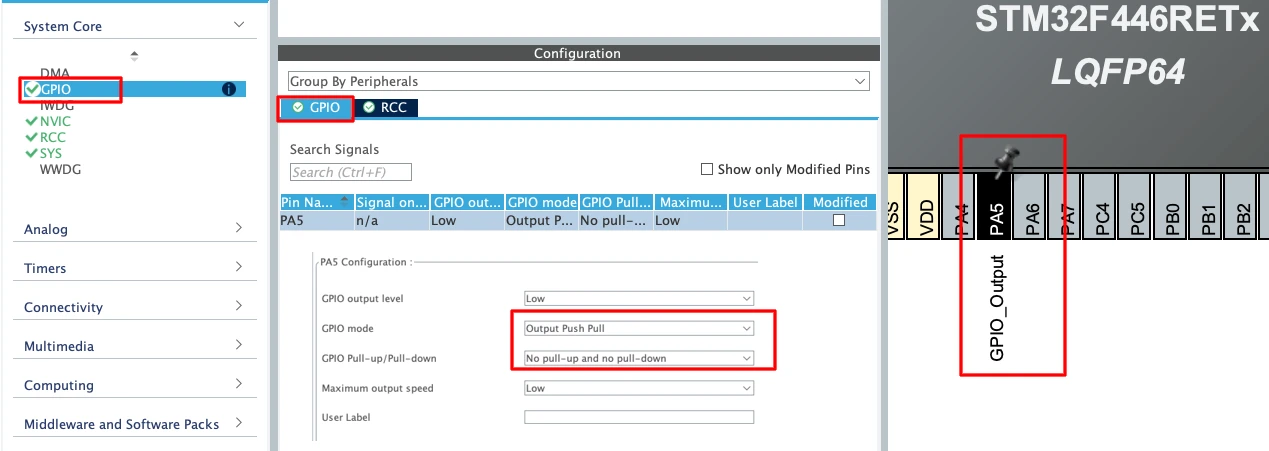
To configure PA5 as an output, go back to the Pinout & Configuration tab in CubeMX. Click on pin PA5 in the graphical MCU view and select GPIO_Output. That is all we need — no pull resistors or speed settings are required for a basic LED output.
Enabling SWD Debug
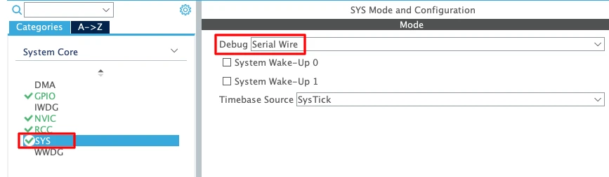
Before generating the code, there is one more thing we should always enable. Go to SYS → Debug and select Serial Wire. This enables the SWD (Serial Wire Debug) interface, which is what the ST-Link uses to program and debug the chip.
Without this, the ST-Link may not be able to connect to the MCU after flashing.
STM32 HAL Code & Results
With the clock configured and the pin set up, we can generate the project and start writing code. This section covers everything from project generation to flashing the board.
Generating the Project
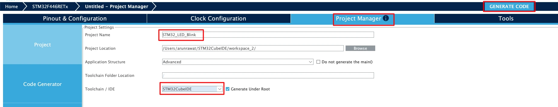
Go to the Project Manager tab. Enter a name for the project and make sure the output path is set correctly. Under the Toolchain/IDE dropdown, select STM32CubeIDE. Then Click Generate Code to generate the project.
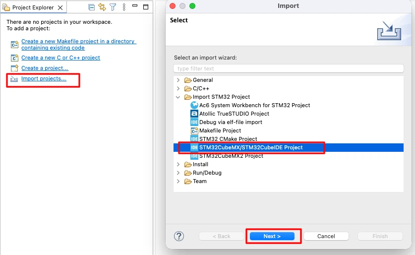
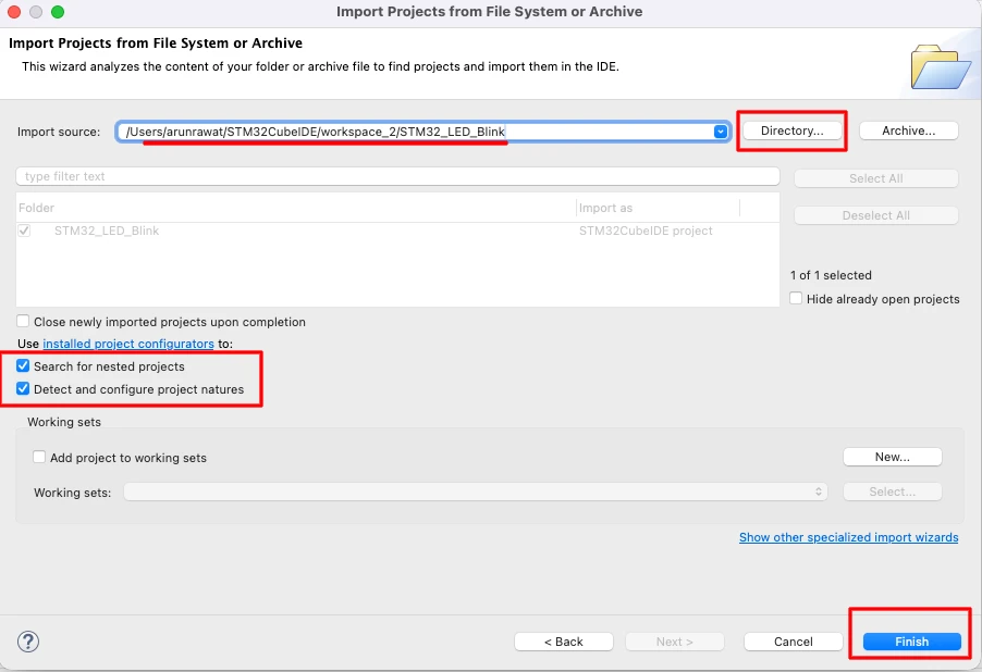
Once generation is complete, click Open Project to launch it directly in CubeIDE — this works on Windows. On Linux or Mac, open CubeIDE manually and use File → Import → STM32 Project, then point it to the generated project folder.
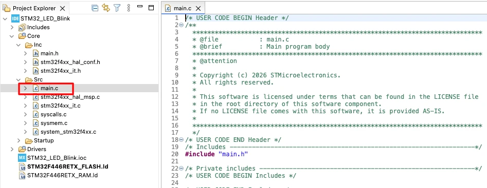
Inside CubeIDE, the project structure will look like this:
Core/Src/— source files, includingmain.cCore/Inc/— header files
We will work mainly inside main.c.
Writing the Blink Code
Open main.c. You will notice comment blocks labeled /* USER CODE BEGIN */ and /* USER CODE END */ throughout the file. We must write all custom code inside these blocks. Anything written outside them will be overwritten if we regenerate the project from CubeMX later.
The while loop in main() already has a USER CODE BEGIN 3 section. We write the LED blink code right there.
The simplest approach is to use HAL_GPIO_TogglePin(), which flips the pin state on every call, paired with HAL_Delay() to control the timing:
/* USER CODE BEGIN 3 */
HAL_GPIO_TogglePin(GPIOA, GPIO_PIN_5);
HAL_Delay(1000);
/* USER CODE END 3 */HAL_Delay() accepts time in milliseconds, so 1000 means a one-second delay. Each loop iteration toggles the LED and waits one second, giving us a 1 Hz blink rate.
To change it to 500 ms, just update the value:
HAL_GPIO_TogglePin(GPIOA, GPIO_PIN_5);
HAL_Delay(500);Build the project using the hammer icon (🔨), then flash it using the Run (▶️) button. The ST-Link handles the download. Once done, the LED should blink at the configured rate.
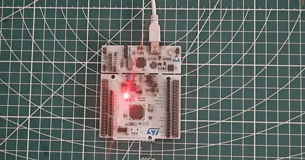
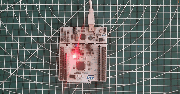
Output
The GIF below shows the Nucleo-F446RE board with the onboard LED blinking every second.
Controlling ON and OFF Time Independently
The toggle approach works well when the ON and OFF durations are equal. But what if we want the LED to stay ON for 500 ms and OFF for 2 seconds? Toggle does not help here since it just flips the state — it has no concept of which state comes next.
For independent control, we use HAL_GPIO_WritePin() instead. This function lets us explicitly set the pin HIGH or LOW:
HAL_GPIO_WritePin(GPIOA, GPIO_PIN_5, GPIO_PIN_SET);   // LED ON
HAL_Delay(500);
HAL_GPIO_WritePin(GPIOA, GPIO_PIN_5, GPIO_PIN_RESET); // LED OFF
HAL_Delay(2000);GPIO_PIN_SET drives the pin HIGH (LED ON), and GPIO_PIN_RESET drives it LOW (LED OFF). The delay after each write controls how long the LED stays in that state.
Build and flash again. The LED will now turn ON for half a second and stay OFF for two seconds, repeating continuously. This gives us full independent control over the ON and OFF durations.
Output
The GIF below shows the LED blinking with a short ON and long OFF pattern — 500 ms ON and 2 seconds OFF.
STM32 Blink LED — First Project Tutorial Video
This video walks through the complete process of creating your first STM32 project using STM32CubeMX and CubeIDE. We configure the system clock for different STM32 boards, set up a GPIO output pin, and write HAL code to blink the onboard LED with controlled timing.
STM32 Blink LED — Frequently Asked Questions
Conclusion
In this tutorial, we created our first STM32 project from scratch. We started with STM32CubeMX, selected the MCU, configured the system clock using the correct HSE source for the board, enabled the SWD debug interface, and set up PA5 as a GPIO output pin.
We then wrote the blink code in STM32CubeIDE using two different approaches. The HAL_GPIO_TogglePin function is the quickest way to blink an LED with equal ON and OFF durations. When we need separate control over each duration, HAL_GPIO_WritePin with GPIO_PIN_SET and GPIO_PIN_RESET gives us that flexibility.
The next tutorial in this series covers the STM32 debugger — how to set breakpoints, watch variable values in real time, and inspect hardware registers to understand exactly what the MCU is doing at every step.
Download STM32 Blink LED CubeMX Project Files
CubeMX project files and HAL source code, tested on real hardware. Free to download — support the work if it helped you.
Browse More STM32 Tutorials

STM32 FMC || LCD PART1 || How to configure for LCD
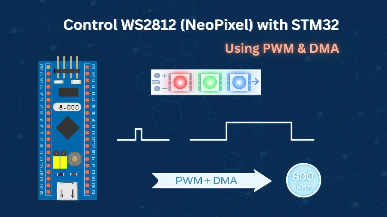
STM32 WS2812 (NeoPixel) Control Using PWM + DMA

WS2812 LEDs using SPI
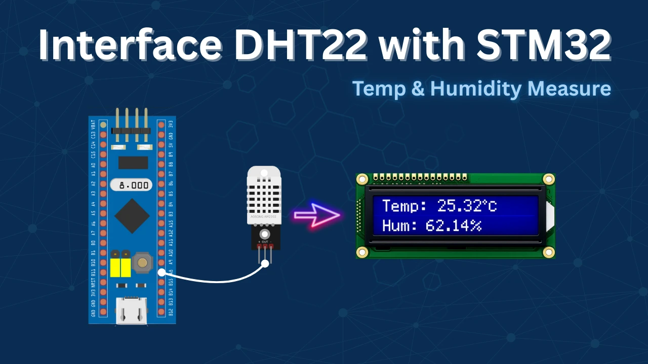
STM32 DHT22 Temperature & Humidity Sensor with HAL

Riverdi STM32-U5 Embedded Display

Subscribe
Login
0 Comments
Newest
