
Updated On: May 10, 2026
STM32 Timer Synchronization in Slave Trigger Mode
When multiple STM32 timers need to start at exactly the same moment — for motor control, phased PWM generation, or precision sequencing — software delays between HAL_TIM_PWM_Start() calls are not reliable enough. The solution is Slave Trigger Mode: a hardware mechanism that holds slave timers frozen until a master timer issues a trigger event, achieving true cycle-accurate synchronization with zero CPU overhead.
This tutorial covers two synchronization topologies using the STM32F446RE:
- Parallel mode — TIM1 (master) triggers TIM2, TIM3, and TIM4 simultaneously using ITR0
- Series (cascade) mode — each timer acts as both slave and master for the next in the chain
You’ll configure everything in STM32CubeMX, write the minimal HAL code, and verify synchronization on an oscilloscope. The complete CubeIDE project is available for download below.
If you’re new to STM32 timers, start with the STM32 PWM Tutorial or browse the full STM32 Timer Tutorial Series which also covers Input Capture, Encoder Mode, Slave Reset Mode, and 3-Phase PWM generation.
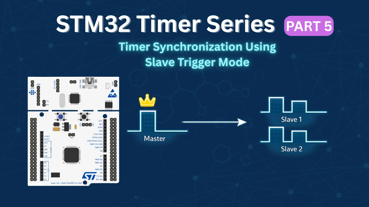
How Slave Trigger Mode Works in STM32
In STM32 timer synchronization, Trigger Mode is used to control when a slave timer begins counting. In this configuration, the slave timer does not start running immediately after initialization. Instead, it waits for a trigger signal generated by the master timer.
When the master timer generates a trigger event — such as an Update Event (UEV) — this signal is internally routed to the slave timer through an internal trigger line (ITR). Upon receiving this trigger, the slave timer resumes its counter operation.
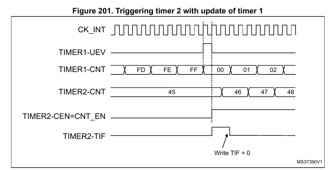
As illustrated in the example above, TIM2 is configured as the slave timer and its counter was paused at a count value of 45. At this point, the counter is not progressing because it is waiting for the trigger input. When TIM1, acting as the master timer, generates an Update Event (UEV), that event serves as the trigger signal. Immediately after receiving this trigger, TIM2 resumes counting from 45 and continues incrementing normally.
It is important to clearly understand one key behaviour of Trigger Mode:
- The counter does not reset to zero when the trigger arrives.
- It simply continues from the value where it was previously stopped.
This makes Trigger Mode different from Reset Mode, where the counter would restart from zero upon receiving a trigger.
Another important point to remember is that Trigger Mode only controls the start (or resumption) of the counter. It does not automatically stop or pause the counter after it begins running. If stopping the timer is required, it must be handled separately either through software control or by using a different slave mode configuration, such as Gated Mode.
Internal Trigger (ITR) Connections
STM32 timers can communicate with each other internally using dedicated trigger lines called Internal Triggers (ITR). These trigger connections allow one timer to control another entirely in hardware, without any CPU intervention.
When a master timer generates a trigger event (TRGO), the signal is routed internally through an ITR line to the slave timer. The slave timer can then respond based on its configured slave mode, such as Trigger Mode, Reset Mode, or Gated Mode.
The connection path typically looks like this:

For example, TIM1 can generate a trigger output that is internally connected to TIM2 through one of the ITR channels. Once the trigger is received, TIM2 can start counting, reset its counter, or gate its operation depending on the selected synchronization mode.
The images below shows the Internal Trigger Connections in different Microcontrollers.
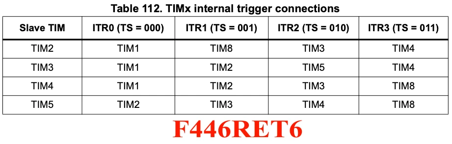
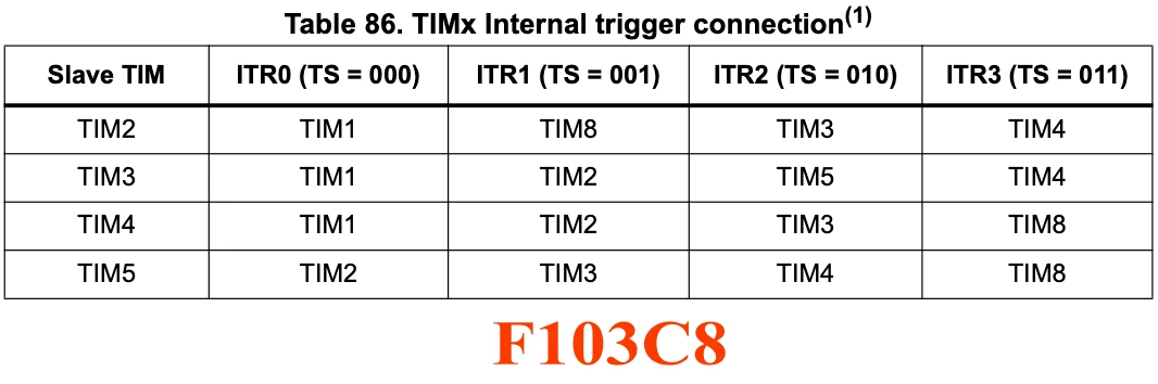
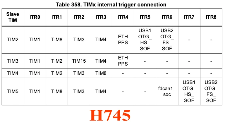
One important thing to understand is that not every timer can connect to every other timer. The available ITR mappings depend on the specific STM32 series and are defined in the reference manual. Before configuring timer synchronization, always check the timer interconnection table provided in the documentation.
Using ITR connections provides several advantages:
- Fully hardware-based synchronization
- No interrupt latency or software jitter
- Precise timing between peripherals
- Minimal CPU overhead
This mechanism is widely used in applications such as synchronized PWM generation, ADC triggering, motor control, and multi-stage timing systems.
Parallel vs. Series Synchronization
STM32 timers can be synchronized in multiple ways depending on how the trigger signals are routed between timers. The two most common approaches are parallel synchronization and series synchronization.
Parallel Synchronization
In parallel synchronization, a single master timer triggers multiple slave timers simultaneously. All slave timers receive the same trigger event and start operating together.
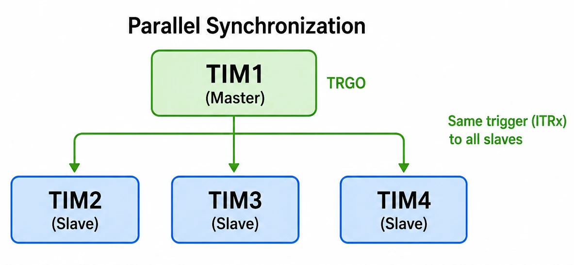
This configuration is useful when several timers must remain aligned in time, such as:
- Generating synchronized PWM outputs
- Starting multiple periodic tasks together
- Driving multi-channel control systems
Since all slave timers receive the same trigger signal, their counters begin operation at nearly the same instant.
Series Synchronization
In series synchronization, timers are connected in a cascade chain where one timer triggers the next.
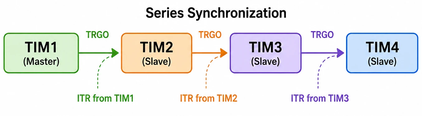
Here, TIM1 acts as the master for TIM2, TIM2 becomes the master for TIM3, and so on. Each timer starts only after receiving a trigger from the previous timer in the chain.
This approach is commonly used for:
- Sequential timing operations
- Multi-stage pulse generation
- Phase-shifted control systems
- Complex timing sequences
Series synchronization allows precise control over timing relationships between different stages of an application while still keeping the entire process hardware synchronized.
CubeMX Configuration for Timer Synchronization
Here we will configure 2 timers. TIM1 will be used as the master timer, whereas, TIM2 will be used as the slave Timer.
TIM1 – Master Timer Setup
We will start with the TIM1 configuration, the master Timer. The image below shows the TIM1 configuration in CubeMX.
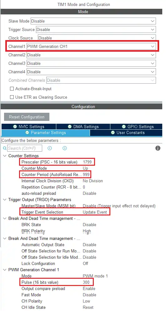
TIM1 will act as a master timer.
- Here I have enabled the PWM for channel 1 so that we can see the output of TIM1
- There is no requirement for the PWM frequency, But I have set it up for 100 Hz, with a duty cycle of 30%.
- You can check out the PWM tutorial if you don’t understand this setting PWM in STM32
- You can check out the PWM tutorial if you don’t understand this setting PWM in STM32
- The main part in this setup is the Trigger Event Selection, which I have set to Update Event (UEV Flag).
- This Update Event signal will be used by the slave Timers, whose counters will start counting upon receiving this signal.
Slave Timer Pin Configuration
The image below shows the pinouts for all the slave timers.
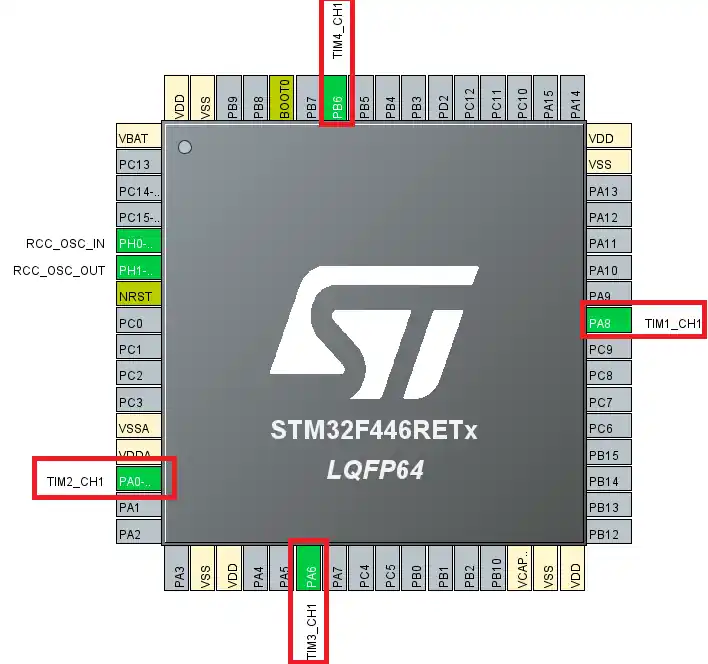
All the 4 pins Here are configures as the output pins. I have connected the all 4 pins to the oscilloscope, so that we can see the output.
TIM2, TIM3, TIM4 – Parallel Slave Setup
As per the STM32F446RE Reference manual, the internal trigger connection between the timers is shown below.
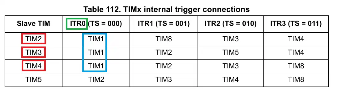
Here the RED box represents the Slave Timers, The BLUE box represents the master Timer, and the GREEN box represents the signal used by the master to control the slave.
As the image shows, the Timers 2, 3 and 4 can be controlled by the same master, TIM1 by using the signal ITR0. Basically we will doing the parallel synchronization, where 1 master will control all 3 slaves at the same time.
Timer 2 Configuration
TIM2, TIM3 and TIM4 will be used as the slave Timers. The image below shows the configuration for the TIM2.

- Here We will configure the TIM in slave mode using the Trigger mode.
- The Trigger source is the signal used by the master to trigger this slave, so it is set to ITR0.
- I have also enabled the PWM output, so that we can see how the timer is behaving.
- Rest is the Frequency and Duty for the PWM, which you can set whatever you want.
- I have used the same frequency and Duty for the TIM3 and TIM4. All three slave Timers are connected to the APB1 bus, so they all will run at same frequency.
Note:
TIM3 and TIM4 have exactly the same setup, so here I have only shows the configuration for TIM2.
Series Mode – CubeMX Configuration
The internal trigger (ITR) connections below shows the Timers linked in the series synchronization.
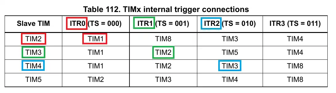
- Here you can see the TIM2 can be controlled by the TIM1 using the signal ITR0.
- Similarly the TIM3 can be controlled by the TIM2 using the signal ITR1.
- And TIM4 can be controlled by the TIM3 using the signal ITR2
So we have 3 Master Timers, TIM1, TIM2 and TIM3 and 3 slave timers, TIM2, TIM3 and TIM4. The cubeMX setup for them is shown below.
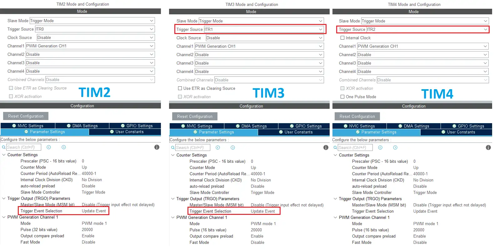
The TIM1 will have the same configuration as earlier, so I have only shown it for the rest of them.
- TIM2 is the slave for TIM1, so the slave Trigger mode is enabled with the trigger source ITR0.
- It is also the master for TIM3, so I have enabled the Trigger Event Selection as Update event.
- It is also the master for TIM3, so I have enabled the Trigger Event Selection as Update event.
- Similarly the TIM3 is the slave for TIM2, so the slave mode triggering is enabled with the trigger source as ITR1
- And it is also the master for TIM4, so the Trigger Event Selection is set as Update event.
- And it is also the master for TIM4, so the Trigger Event Selection is set as Update event.
- TIM4 is the slave for TIM3, so the slave mode triggering is enabled with ITR2 as the trigger source.
Timer Synchonization HAL Code & Oscilloscope Results
STM32 HAL code for Timer Synchronization
There isn’t much to modify in the code for this configuration. Inside the main() function, we simply need to start the PWM outputs for all the configured timers. The same code applies to both parallel and series synchronization.
  /* USER CODE BEGIN 2 */

  HAL_TIM_PWM_Start(&htim2, TIM_CHANNEL_1);
  HAL_Delay(500);

  HAL_TIM_PWM_Start(&htim3, TIM_CHANNEL_1);
  HAL_Delay(500);

  HAL_TIM_PWM_Start(&htim4, TIM_CHANNEL_1);
  HAL_Delay(500);

  HAL_TIM_PWM_Start(&htim1, TIM_CHANNEL_1);

/* USER CODE END 2 */In this example, I have started the PWM outputs for the slave timers first. The 500 ms delay between each start command is intentionally added so that we can clearly observe the behavior of each timer on the oscilloscope.
With this setup, if the Slave Trigger Mode is not configured correctly, you would see the PWM from TIM2 start immediately. After 500 ms, TIM3 would begin generating its PWM signal, and this sequence would continue. Finally, the PWM output of the master timer, TIM1, would start at the end.
This staggered startup makes it easy to verify whether synchronization is actually working or not. If everything is configured correctly, the slave timers will not generate PWM output until the master timer issues the trigger event.
Parallel Mode – Oscilloscope Output
Here is the oscilloscope output showing the resulting PWM signals.
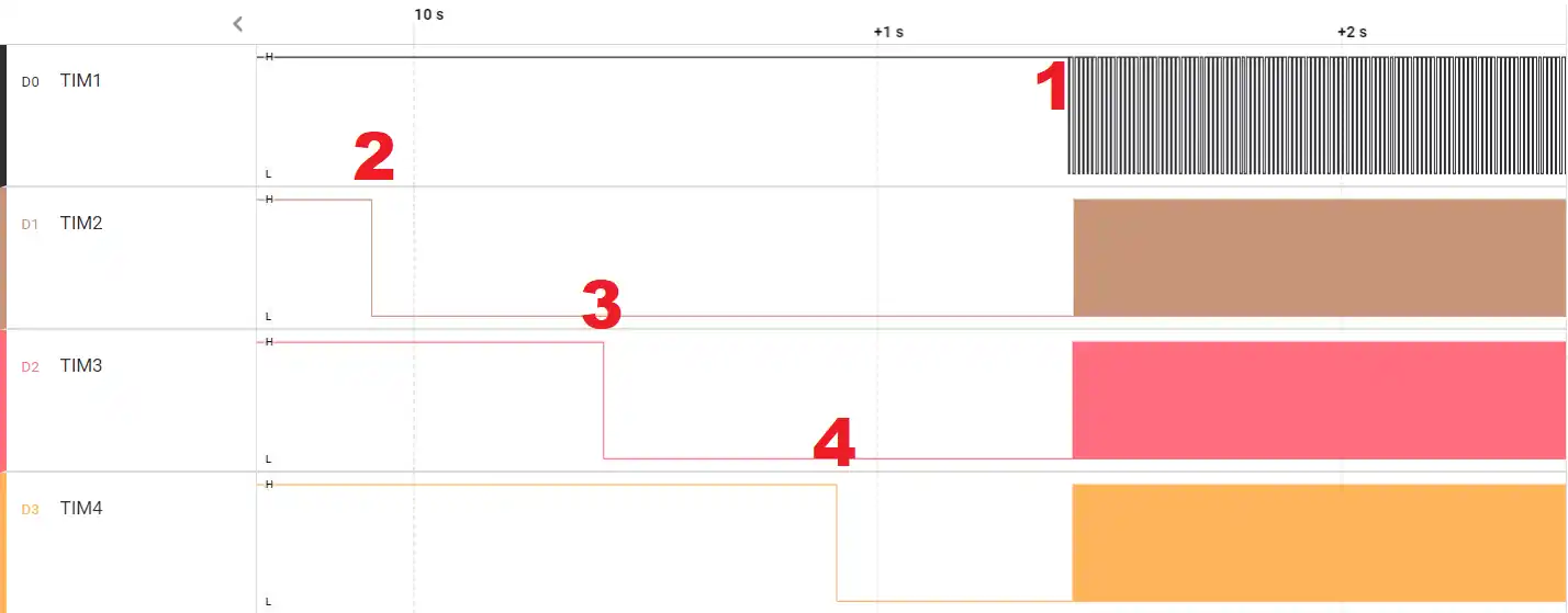
Here I have marked the pins 2, 3, 4 and 1.Keep in mind that the channel polarity is set to LOW, so a HIGH output can be seen as LOW here.
Just a remainder, in the PWM signal, the output remains high when the counter counts from 0 to CCR (Pulse) value. After that the output remains LOW from the CCR value to the ARR value.
- The PWM for TIM2 starts at mark 2. The counter is initialized with 0 but it never counts up, as it is waiting for the Trigger signal.
- The PWM is working, but since the counter is stuck at 0 and so the output remains HIGH (LOW in the scope).
- The PWM is working, but since the counter is stuck at 0 and so the output remains HIGH (LOW in the scope).
- The PWM for TIM3 and TIM4 starts in the similar manner. Their counters are also waiting for the Trigger signal.
- At the mark 1, the TIM1 finally starts. After this point The PWM for all the slave timers starts showing the waveform.
Let’s zoom into the mark 1. The image below shows what exactly happens at that point.
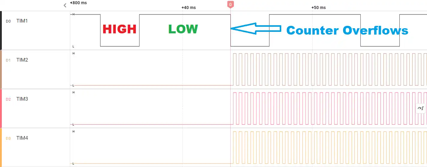
As I mentioned the Channel Polarity is inverted, so the signal remain high for 30% of the time and Low for 70% of the time. This is as per the PWM setup we did for the TIM1.
- At the 0 marker, the counter of the TIM1 overflows.
- This generates the Update Event (UEV).
- Once the slave Timers receive this trigger signal, their counters start counting and you can see the PWM waveform for all three slaves.
- All three of them starts at exactly the same time. This is the advantage of using the slave mode Triggering.
Series Mode – Oscilloscope Output
The code remains the same as what we used earlier, so we will just see the output on the scope.
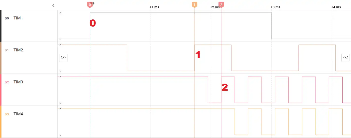
You can see the output is a bit different from what we got the last time.
- Here marker 0 is the point where the overflow occurs for the TIM1, and hence the TIM2 starts after that.
- Marker 1 is the point where the TIM2’s counter overflows. TIM3 starts immediately after this point.
- TIM3’s counter overflows at the marker 2, and TIM4 starts after this point.
STM32 Timer Synchronization – Slave Trigger Mode | Video Tutorial
This video walks through the complete setup of STM32 Timer Synchronization in Slave Trigger Mode. We configure TIM1 as master and TIM2, TIM3, TIM4 as slaves in CubeMX, write the HAL PWM start code, and verify both parallel and series synchronization on an oscilloscope — showing exactly when each slave timer starts counting after the master issues its Update Event trigger.
STM32 Timer Synchronization FAQs
Conclusion
STM32 Slave Trigger Mode gives you hardware-guaranteed timer synchronization with no CPU overhead. Once you understand the ITR connection map for your specific device and set the Trigger Event Selection correctly on the master, synchronizing two, three, or four timers is a matter of a few CubeMX settings and a single HAL start call.
The parallel and series configurations shown here cover the two fundamental topologies. Parallel mode is ideal when multiple outputs must begin in phase — motor windings, LED arrays, multi-channel ADC sampling. Series (cascade) mode is the right choice when you need deliberate, sequenced delays between stages, or when you’re extending a timer’s effective period beyond its 16-bit limit.
Download the project files below, load them in CubeIDE, and verify both configurations on your own hardware. For related techniques, see 3-Phase PWM Generation and Slave Reset Mode.
Download STM32 Timer Synchronization Project Files
Complete CubeIDE project with CubeMX config for TIM1 (master) and TIM2/TIM3/TIM4 (slaves) in both parallel and series Slave Trigger Mode. HAL source included. Free to download — support the work if it helped you.
Browse More STM32 Timer Tutorials
STM32 Timers (Part 2): How to Measure PWM Input Signal
STM32 Timers (Part 3): How to use the Timer Encoder Mode
STM32 Input Capture: Measure Frequency & Pulse Width
STM32 Timers (Part 6): Timer Synchronization for 3-Phase PWM Generation
STM32 Timers (Part 7): Timer synchronization using Slave Reset mode



Hello!
STM32f407 I use master timer 2, slave timers 3, 4, 8. The problem is that with the same setting 3 and 4, the timer is synchronized, and 8 has a delay. I used LL_TIM_OC_EnablePreload(TIME8,LL_TIM_CHANNEL_CH3); TIM8->CR1 |= TIM_CR1_ARPE; It got better. The first run goes without problems, but if you turn off the counter and re-enable synchronization again, the timer slows down.
hello
thanks to your education.
i see an example code that is for cubemx
and it use itr1 to triger tim1
but in datasheet we need tim2 , but code work
and i dont know why???
stm32f1
Hello,
Thank you very much, Sir.
Would you mind, can I translate your expanation to Thai?