Home ▸ STM32 Tutorials ▸ STM32 HAL ▸
Updated On: May 9, 2026
STM32 RS485 Communication with MAX485: UART Setup & Code
RS485 is the communication standard behind most industrial embedded systems — Modbus sensor networks, motor controllers, energy meters, building automation buses. Where UART gives you two devices over a few meters, RS485 gives you up to 32 nodes over 1200 meters in electrically noisy environments. The STM32 UART peripheral handles the data; the MAX485 transceiver handles the bus.
In this tutorial, you will interface the MAX485 RS485 module with STM32 and establish half-duplex communication between two boards — an STM32F103 and an STM32F446. You will learn the module pinout, how the A/B differential signals work, how to wire the boards, configure UART in CubeMX, control the DE/RE direction pin, and use HAL_UARTEx_ReceiveToIdle_IT() for interrupt-driven reception. A complete request-response example is included with verified results.
This tutorial uses UART under the hood — if you are not familiar with STM32 UART configuration or the idle-line receive interrupt, check the prerequisite tutorials first:
STM32 RS485: How It Works
What is RS485 and Why Use It?
RS485 is a serial communication standard that uses differential signaling — data is transmitted as the voltage difference between two wires (A and B) rather than a single voltage level relative to ground. This makes it highly resistant to electrical noise, which is why it’s the default choice for industrial environments, long cable runs, and multi-device networks.
Compared to UART, which is limited to two devices over a few meters, RS485 supports up to 32 nodes on a single bus and cable lengths up to 1200 meters. In STM32 projects, RS485 is used everywhere from Modbus sensor networks and motor controllers to energy meters and building automation systems.
The STM32 UART peripheral generates the data — the MAX485 transceiver converts that UART signal to and from the differential RS485 bus levels. No changes to the UART configuration are needed beyond adding the DE/RE direction control pin.
RS485 vs UART: Key Differences
| Feature | UART | RS485 |
|---|---|---|
| Topology | Point-to-point only | Multi-drop (up to 32 nodes) |
| Max cable length | ~3–5 meters | Up to 1200 meters |
| Signaling | Single-ended | Differential (A/B pair) |
| Noise immunity | Low | High |
| Direction control | None needed | DE/RE pin required |
| Typical use | Debug, short-range data | Industrial, Modbus, long-distance |
RS485 MAX485 Module Overview
An RS485 to TTL converter is a communication interface module that allows microcontrollers, like STM32, to communicate over long distances using the RS485 protocol. It converts the differential RS485 signals into standard TTL-level serial data, which can be read by UART peripherals on microcontrollers. RS485 is known for its robustness, noise immunity, and ability to support multiple devices on the same bus, making this converter ideal for industrial and embedded systems applications.
These modules often use the MAX485 transceiver chip, which supports half-duplex communication and is capable of driving long cable lengths with high reliability.
Important Features of RS485 to TTL Converter:
- Differential Signaling for Long-Distance Communication: It uses differential signal transmission, which reduces noise and allows data to be transmitted over distances of up to 1200 meters.
- Multi-Device Bus Support: RS485 supports up to 32 devices on the same communication line, enabling multi-node communication in a single network.
- Wide Voltage Compatibility: Operates on a 5V power supply and provides TTL-level output compatible with 3.3V or 5V microcontrollers.
- Driver/Receiver Enable Pins (DE/RE): The DE and RE pins allow precise control of data direction, essential for implementing half-duplex communication between devices.
The signal level used during the RS485 communication method typically ranges from -7V to +12V. The microcontroller pins are generally not designed to handle these levels. This is why these signals needs to be converted to low voltages, for eg ±3V. The module have the MAX485 chip on it, which does most of the job of conversion.
RS485 Module Pinout
The pinout of the module is shown below
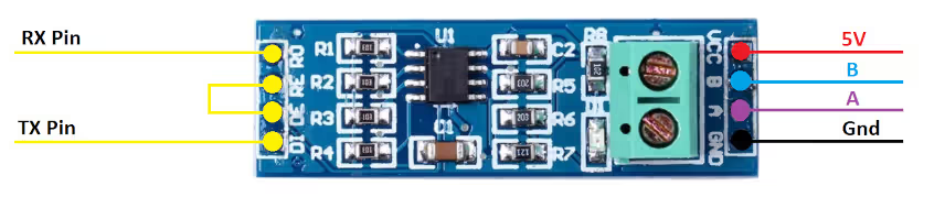
On the left side of the module, the RO pin connects to the RX pin of the UART, and the DI pin connects to the TX pin.
The RE and DE Pins are responsible for setting the module in Receiver or Transmitter mode.
- When the RE pin is LOW and DE pin is LOW, the Module is set in the Receiver mode.
- When the DE pin is HIGH and RE pin is HIGH, the Module is set in the Transmitter mode.
The Pin A and the Pin B are the output pins which carries the transmission signal.
Let’s take an example where we provide the data, 0x95 (10010101) to the module. If the Module is powered with 5V, the output on pins A and B will be as shown below
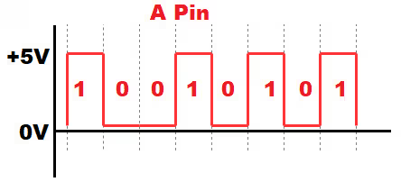
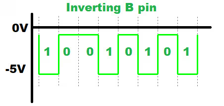
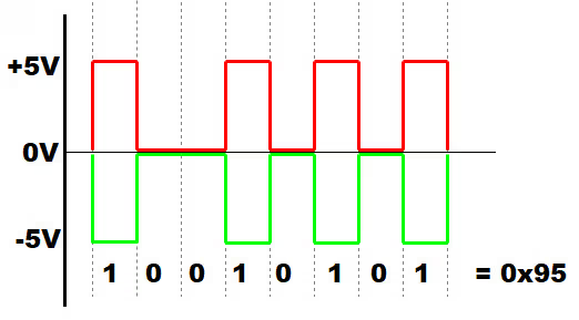
- Since A is the non-inverting pin, it’s output will be in sync to the input. It varies between 0 to +5V
- B is the inverting pin, so the output is inverted and varies between -5V to 0
- When the second module receives these as inputs, it decode the data based on the voltage differences.
- If the voltage difference is maximum, the bit is 1, and if the difference is 0 the bit is 0
- This data is then converted to lower voltages (0 to 3V) to suit the MCU requirement
STM32 and MAX485 Wiring & CubeMX Setup
STM32 to MAX485 Pin Connections
The wiring is the same for both the STM32F103 and STM32F446 used in this tutorial. Use UART1 on PA9/PA10, with PA8 as the direction control output.
Below is the connection diagram of the module with the STM32F103C8 controller. The connection will remain same with the F446 also, so I am just showing one of them here.
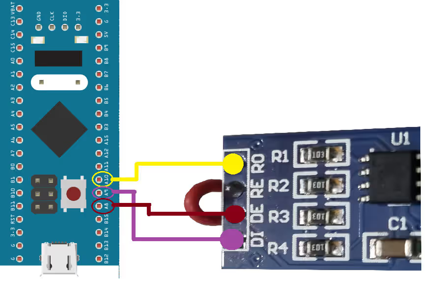
As demonstrated above, the RO (Receiver Output) pin of the MAX485 module is connected to PA10, which serves as UART1 RX on the STM32. The DI (Driver Input) pin is connected to PA9, configured as UART1 TX.
The RE (Receiver Enable) and DE (Driver Enable) pins are tied together and connected to PA8, which is configured as a digital output on the STM32. This setup allows the microcontroller to control whether the module is in transmit or receive mode.
| MAX485 Pin | Function | STM32 Pin | Notes |
|---|---|---|---|
| RO | Receiver Output | PA10 | UART1 RX |
| DI | Driver Input | PA9 | UART1 TX |
| RE | Receiver Enable | PA8 | Tied with DE, output control |
| DE | Driver Enable | PA8 | Tied with RE, output control |
| VCC | Power Supply | 5V | According to module specs |
| GND | Ground | GND | Common ground |
Note:
Power the MAX485 module from 5V, not 3.3V. The module’s VCC pin requires 5V for correct differential output levels. The RO and DI pins are TTL-compatible with 3.3V STM32 boards, but VCC itself must be 5V.
STM32 CubeMX Configuration for RS485
Before writing the code for RS485 communication, it is essential to properly configure the STM32 peripherals using CubeMX.
The UART configuration in the CubeMX is shown below.
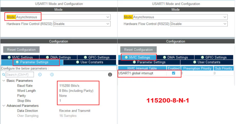
UART1 is configured with its default settings, using a baud rate of 115200 and 8-N-1 format (8 data bits, no parity, 1 stop bit). Additionally, the UART receive interrupt has been enabled to allow the STM32 to receive data from the second controller asynchronously.
The Pins used for this project are shown below.
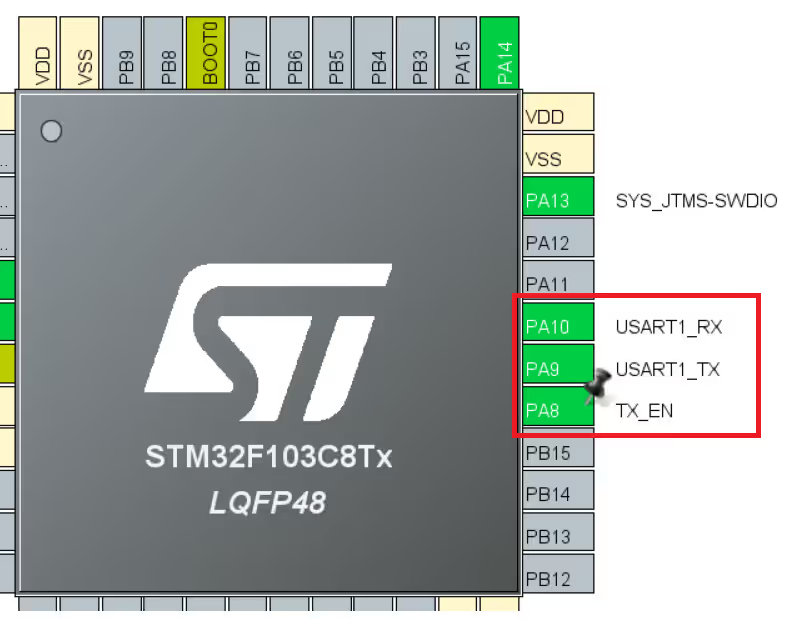
The PA8 pin is configured as a digital output and renamed TX_EN. It controls the MAX485 module’s mode: high for transmit and low for receive, allowing the STM32 to switch between sending and receiving data on the RS485 bus.
STM32 RS485 Code, Example & Results
As previously mentioned, the goal is to establish communication between the two microcontrollers. The STM32F103 will initiate the communication by transmitting a message, and upon receiving this message, the STM32F446 will respond accordingly. This setup demonstrates a simple request-response mechanism using RS485.
The sendData() Helper Function
This function handles the DE/RE direction switching around every transmission. It must be used for all transmissions — bypassing it and calling HAL_UART_Transmit() directly will leave the module stuck in transmit mode and block all reception.
void sendData(uint8_t *data)
{
    // Switch to transmit mode
    HAL_GPIO_WritePin(TX_EN_GPIO_Port, TX_EN_Pin, GPIO_PIN_SET);
    HAL_UART_Transmit(&huart1, data, strlen((char*)data), 1000);
    // Switch back to receive mode immediately after
    HAL_GPIO_WritePin(TX_EN_GPIO_Port, TX_EN_Pin, GPIO_PIN_RESET);
}The module is kept in receive mode at all times except during the brief window when HAL_UART_Transmit() is executing. Since HAL_UART_Transmit() is blocking, the GPIO pin is set back to LOW only after all bytes have been shifted out — ensuring the bus is not released mid-transmission.
STM32F103 Code (Initiator)
uint8_t TxData[16];
uint8_t RxData[16];
int indx = 0;

int main(void)
{
    // ... HAL_Init, SystemClock_Config, MX_GPIO_Init, MX_USART1_UART_Init ...

    HAL_UARTEx_ReceiveToIdle_IT(&huart1, RxData, 16);  // Start reception

    while (1)
    {
        sprintf((char*)TxData, "F103 %d", indx++);
        sendData(TxData);
        HAL_Delay(1000);
    }
}

void HAL_UARTEx_RxEventCallback(UART_HandleTypeDef *huart, uint16_t Size)
{
    // Re-arm the interrupt — HAL disables it after each trigger
    HAL_UARTEx_ReceiveToIdle_IT(&huart1, RxData, 16);
}HAL_UARTEx_ReceiveToIdle_IT() receives incoming data into RxData until the UART RX line goes idle — ideal for RS485 where frame length is variable and there is no fixed terminator. The interrupt fires when the line has been idle long enough after the last byte, indicating the frame is complete. The callback must re-arm the interrupt each time because HAL disables it after each event.
STM32F446 Code (Responder)
The F446’s main loop is empty — all logic lives in the callback. When a message arrives, the first four bytes are overwritten to identify the responder, and the modified frame is sent back immediately.
uint8_t RxData[64];

// main(): same init as F103, then:
// HAL_UARTEx_ReceiveToIdle_IT(&huart1, RxData, 64);
// while(1) {}

void HAL_UARTEx_RxEventCallback(UART_HandleTypeDef *huart, uint16_t Size)
{
    // Overwrite "F103" with "F446" to identify the response source
    RxData[0] = 'F';
    RxData[1] = '4';
    RxData[2] = '4';
    RxData[3] = '6';

    sendData(RxData);  // Send modified frame back to F103

    // Re-arm reception
    HAL_UARTEx_ReceiveToIdle_IT(&huart1, RxData, 64);
}Results
Inspecting the F103’s TxData and RxData buffers in the debugger confirms the round-trip:
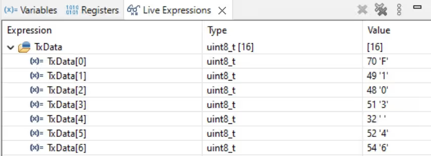
- F103 transmits:
"F103 46" - F446 receives it, replaces
"F103"with"F446", transmits back - F103 receives:
"F446 46"
The counter value (46 in this example) is preserved through the round trip, confirming that the DE/RE switching, UART framing, and idle-line detection are all working correctly.
STM32 RS485 with MAX485 — Video Tutorial
This video walks through the complete RS485 setup with STM32 using the MAX485 module. It covers the module pinout, differential A/B signal behaviour, wiring the STM32F103 and STM32F446, CubeMX UART and GPIO configuration, the DE/RE direction control logic, and a live demonstration of the two-board request-response exchange.
STM32 RS485 — Frequently Asked Questions
Conclusion
In this tutorial, we set up RS485 communication between two STM32 boards using the MAX485 module and the UART peripheral. The core pattern — pull TX_EN HIGH, transmit, pull TX_EN LOW immediately after — is the foundation of every RS485 implementation regardless of complexity. Pair that with HAL_UARTEx_ReceiveToIdle_IT() for reliable variable-length frame reception and you have everything needed for a production-ready RS485 link.
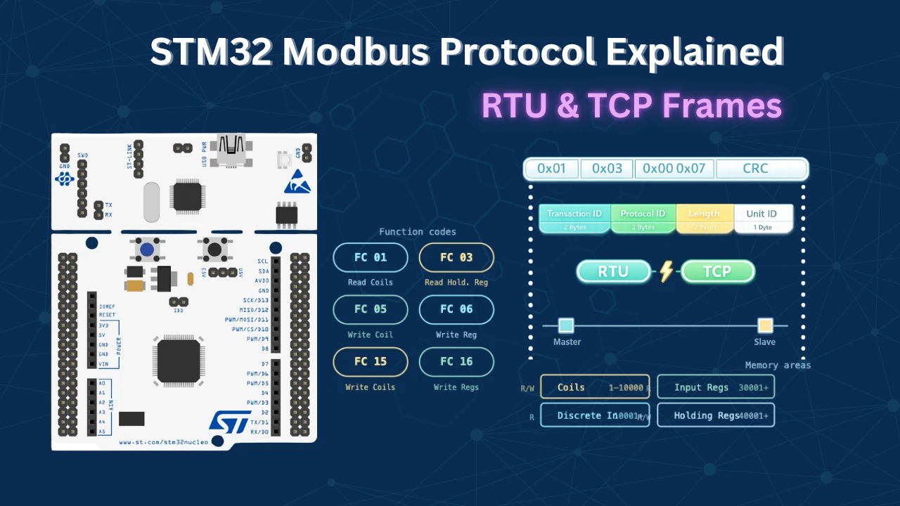
This same setup is exactly what Modbus RTU runs on. The next logical step from here is implementing the Modbus RTU protocol on top of this RS485 layer — the ControllersTech Modbus series covers that in full, starting with the Modbus Protocol 101 guide linked below.
Download STM32 RS485 MAX485 Project Files
Complete CubeIDE projects for both the STM32F103 (initiator) and STM32F446 (responder) — includes UART configuration, DE/RE direction control, ReceiveToIdle interrupt, and the request-response example. Free to download — support the work if it helped you.
Browse STM32 Modbus RTU Tutorials

Modbus #1. STM32 Master Reads Holding and Input Registers

Modbus #2. STM32 Master Reads Coils and inputs

Modbus #3. STM32 Master Writes single Coil and Holding Register
Modbus #3.1 STM32 Master Writes Multiple Coils and Registers

Modbus #4. STM32 as Slave || Read Holding and Input Registers


I have Invalide CRC ERROR in master modbus tools with the same baudrate
I don’t understand. Please elaborate.
Hello,
I am facing a issue that I could not receive proper data or continious data at both end.
Check for the baud rate. If the garbage data is received, it is because of the baud rate. Also make sure the clock configuration is correct as per your MCU.
I don’t understand what you mean continuous data is not being received.
Hi, I’m using STM32H750VB, I can’t find the instruction “HAL_UARTEx-ReceiveToIdle_IT()” in this family and I have error in my code.
Can I use “HAL_UART_Receive_IT()” instead of it??
It is available across all STM32 families. Make sure you have enabled the uart in the cubeMX. Also check if you are writing the function properly. It is not “HAL_UARTEx-ReceiveToIdle_IT()”, but “HAL_UARTEx_ReceiveToIdle_IT”