
Updated On: April 30, 2026
STM32 UART DMA Receive: Normal Mode & Circular Mode
UART receive in blocking mode is simple but CPU-intensive, the processor sits idle waiting for every byte. Interrupt mode is better, but fires too frequently under heavy data rates. For anything beyond occasional small packets — a file transfer, continuous sensor stream, GPS NMEA feed, or audio data — UART DMA receive is the correct tool. The DMA controller moves bytes directly from the UART peripheral to your buffer, the CPU does nothing until the transfer is done.
This tutorial covers two DMA reception approaches. Normal mode handles fixed-size data: you tell the DMA exactly how many bytes to expect, it fills the buffer, fires a callback, and stops. Circular mode handles continuous or unbounded data: the DMA wraps automatically, the half-complete and complete callbacks fire as each 128-byte half arrives, and the main loop handles any partial remainder at the end. Both examples receive a file sent from a serial terminal, verify the contents against the original, and demonstrate the complete buffer management pattern needed for real projects.
Before continuing, you should be familiar with UART reception basics from Part 3: Receive Data using Blocking & Interrupt Mode.
This is the Part 4 in the STM32 UART Series. You can access the other tutorials of this series here:
- Configuration & Transmit Data
- Transmit using Interrupt & DMA
- Receive using Blocking & Interrupt Mode
- UART Idle Line (Interrupt & DMA)
- Half Duplex Communication
STM32 UART DMA: How It Works & When to Use It
When receiving data through UART in STM32, you can use different methods like blocking mode, interrupt mode, or DMA mode. While blocking and interrupts work fine for small or occasional data, they quickly become inefficient when handling continuous streams or large amounts of data. This is where UART with DMA becomes a better choice.
Limitations of Blocking and Interrupt Modes
- Blocking mode: In this method, the CPU waits until the data transfer is complete. This wastes processing time because the CPU cannot perform other tasks while waiting. For large data or continuous reception, blocking mode severely reduces system performance.
- Interrupt mode: Interrupts improve efficiency by notifying the CPU only when data is available. However, if the incoming data is very frequent or in large bursts, the CPU must handle too many interrupts. This can cause overhead, reduce responsiveness, and even lead to missed data if the system cannot keep up.
Both of these methods are not ideal when you need high-speed data reception or continuous communication.
Advantages of UART DMA
Using DMA (Direct Memory Access) with UART solves these problems:
- Reduced CPU load: DMA transfers data directly between UART and memory without constant CPU involvement. The CPU is free to handle other tasks.
- Continuous streaming: With DMA in Circular mode, you can continuously receive data into a buffer without worrying about missing bytes. This is perfect for applications like sensor logging, GPS data, or wireless communication.
- Faster throughput: Since DMA works independently of the CPU, it can handle data transfers more efficiently and at higher speeds. This ensures reliable communication even in demanding applications.
UART DMA receive in STM32 makes communication more efficient, reduces processing overhead, and enables smooth handling of real-time data streams.
Blocking vs Interrupt vs DMA: Comparison Table
| Feature | Blocking Mode | Interrupt Mode | DMA Mode |
|---|---|---|---|
| CPU Usage | Very high (CPU waits until data transfer finishes) | Medium (CPU wakes up frequently for each interrupt) | Very low (DMA handles transfers independently) |
| Efficiency | Poor for large or continuous data | Better than blocking but still limited at high data rates | Excellent, suitable for continuous or high-speed data |
| Throughput | Limited by CPU speed | Higher than blocking, but may drop with heavy load | Very high, as DMA can transfer data in the background |
| Complexity | Simple to implement | Moderate, requires ISR handling | Slightly more complex setup, but handled easily with HAL functions |
| Best Use Case | Small, occasional data | Medium data rates, when CPU load is light | Continuous streaming, large data transfers, high-speed communication |
Hardware Setup: VCP Boards and FT232 Adapter
We will use the STM32 MCU to send the data to the computer. Some of the Nucleo and Discovery dev boards from ST supports the virtual com port. This feature enables the USB connected for the ST-link to be also used for the data transmission between the MCU and the computer.
The Virtual Com Port is supported by many Nucleo and Discovery boards but not all. You need to check the schematic of the board to confirm whether the respective board supports it.
Below are the images from the schematic of the Nucleo F446RE and Discovery F412.
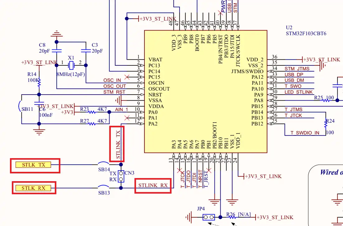
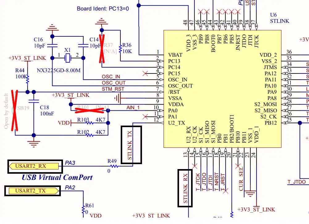
As you can see in the images above, both Nucleo F446RE and Discovery F412 supports the USB Virtual Com Port. So if you are using either of these boards, you do not need to use an additional module to communicate to the computer. The USB used for the ST link can also be used for the communication.
Not all the boards support this Virtual Com port feature. Below is the image from the schematic of the very famous STM32F4 Discovery board.
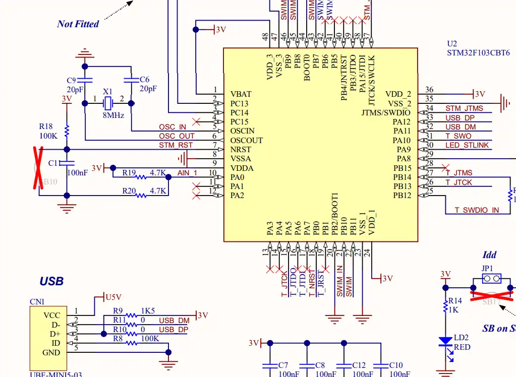
As you can see in the image above, there is no virtual com port in the F4 Discovery board. In such cases we can use some module to convert the UART signals to the USB, which is connected to the computer.
The image below shows the connection between the MCU and the FT232 USB to UART converter.
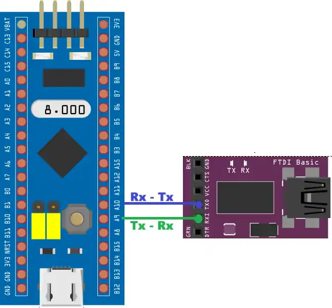
The UART is always connected in the cross connection, connecting the TX pin of the MCU to the RX of the device and the RX to the TX of the device. The module then connects to the computer using the USB.
STM32 UART DMA Normal Mode: Fixed-Size Reception
Let’s assume a case where we want to receive a large amount of data, and our MCU has enough RAM to store that data into a buffer. We can use the DMA in NORMAL mode to receive this data over the UART and then store the data into the buffer.
A situation like this can work for few kilobytes of data as most of the STM32 MCUs has RAM in few kilobytes. But if you want to store an audio file or a video file, then you can’t afford to use a single buffer.
When to Use Normal Mode
DMA Normal mode is perfect when:
- The incoming data has a known size
- You’re expecting the full buffer to fill once
- You can afford to pause data reception while processing
It’s simple and fast but not ideal for continuous streaming. I will demonstrate how to use a 4KB buffer with HAL_UART_Receive_DMA() and switch between size and data phase using HAL_UART_RxCpltCallback().
CubeMX Configuration for DMA Normal Mode
The image below shows the cubeMX configuration to enable the UART DMA in Normal mode.
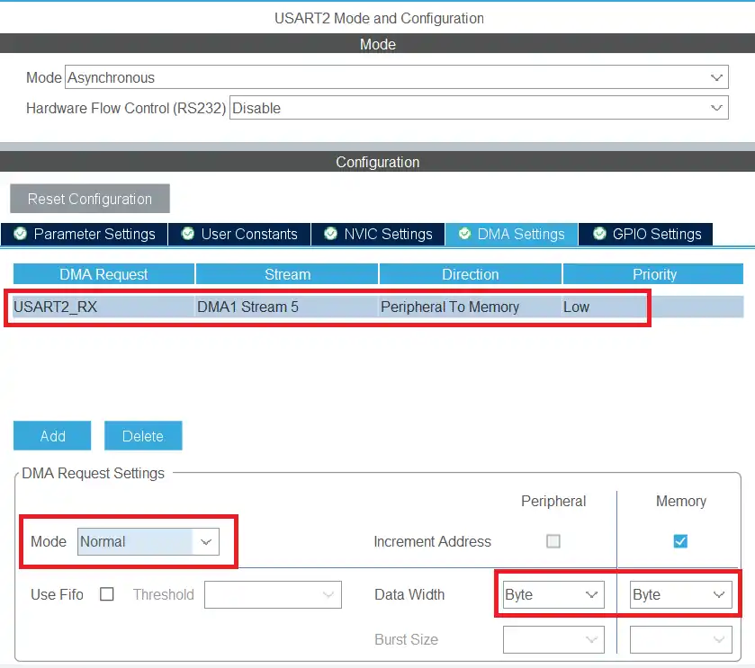
The DMA request is set for USART2_RX as we are receiving the data via the DMA. The data width is Byte as the UART transfers the data in bytes. The DMA mode is set as Normal.
The rest of the UART configuration is same as the previous tutorials with Baud Rate of 115200 with 8 data bits, 1 stop bit and no parity.
DMA Normal Mode Code
We need to know the size of the incoming data. So the sender should first send 4 bytes of the size data followed by the data itself. If you are receiving larger data, you can change the length of the size data bytes.
In the main function, we will set the DMA to receive 4 data bytes for the size.
uint8_t RxData[4096]
int main()
{
  ....
  HAL_UART_Receive_DMA(&huart2, RxData, 4);
  while (1)
  {
    HAL_GPIO_TogglePin(GPIOA, GPIO_PIN_5);
    HAL_Delay(1000);
  }
}The function HAL_UART_Receive_DMA will receive 4 data bytes. Once all the 4 bytes has been received, the interrupt will trigger and the UART Receive Complete Callback will be called.
int isSizeRxed = 0;
uint16_t size = 0;

void HAL_UART_RxCpltCallback(UART_HandleTypeDef *huart)
{
	if (isSizeRxed == 0)
	{
		size = ((RxData[0]-48)*1000)+((RxData[1]-48)*100)+((RxData[2]-48)*10)+((RxData[3]-48));
		isSizeRxed = 1;
		HAL_UART_Receive_DMA(&huart2, RxData, size);
	}
  else if (isSizeRxed == 1)
	{
		isSizeRxed = 0;
		HAL_UART_Receive_DMA(&huart2, RxData, 4);
	}
}The callback will be first called when the 4 size bytes are received. The isSizeRxed variable was 0 in the beginning, therefore, we will calculate the size using the 4 bytes of the RxData buffer.
The size bytes are transferred in the Ascii form and hence we need to subtract 48 to convert them to integer equivalent.
After calculating the size, we will set the variable isSizeRxed to 1 so that we don’t enter this loop again. Then we will call the function HAL_UART_Receive_DMA to receive the required number of data bytes as calculated by the size variable.
Once all the required number of data bytes has been received, we will enter this function again. This time the variable isSizeRxed is set to 1, so the else condition will execute. Here we will reset the variable isSizeRxed to 0 and receive the 4 size bytes. This will make this entire loop to run forever.
Now we can receive the large data of any size, but it should be less than 4KB. This is because we have defined a buffer of 4KB to store the data. Although we need to send the size first, followed by the data itself.
Normal Mode Result
The images below shows the data sent by the serial console and the data stored in the RxData buffer in the CubeIDE debugger.
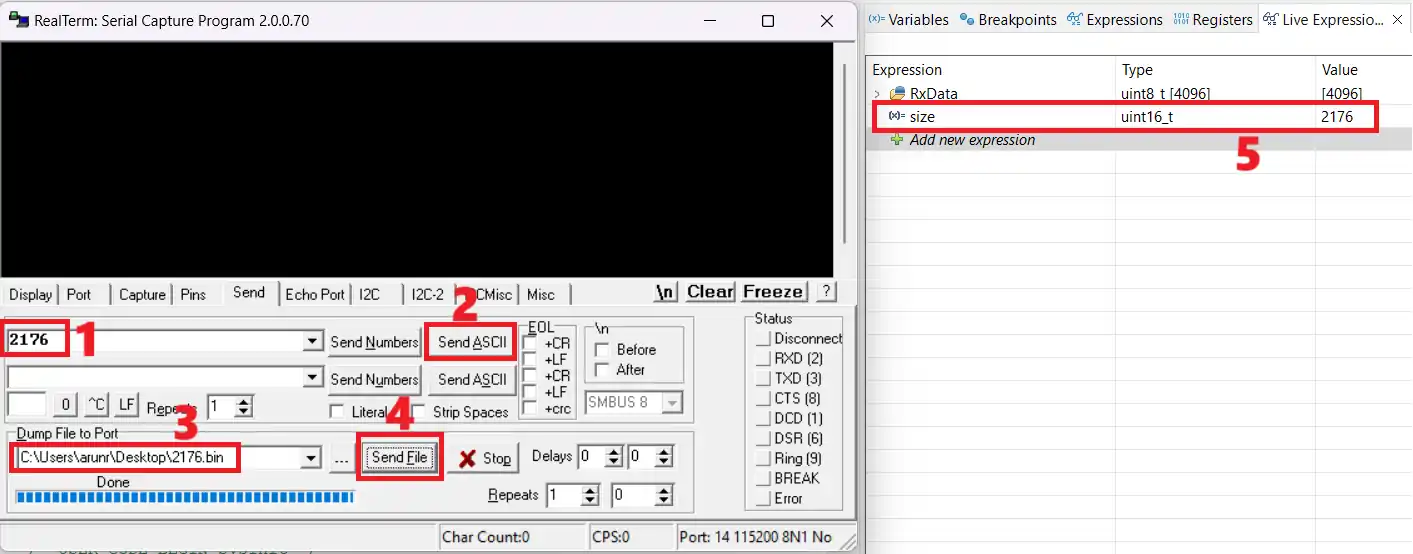
The numbers marked on the image are explained below.
- I am going to send a file of size 2176 bytes, so I need to first send the size.
- Send the size data (“2176”).
- Select the file that contains the data.
- Send the file.
- The MCU has extracted the size data, and it is expecting 2176 bytes to be received.
The RxData buffer has the data. To make sure we received the entire data, we will cross check the start and end part with the actual data. The images below shows the comparison between the actual data, and the data stored in the RxData buffer.

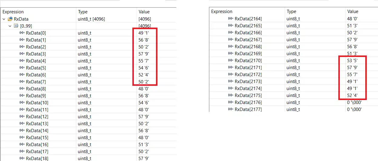
You can see the actual data in the file and the data stored in the RxData buffer have the same content in the beginning and in the end. This means we have received entire data from the file.
STM32 UART DMA Circular Mode: Continuous Streaming
When to Use Circular Mode
Let’s assume another case where we want to receive an audio or a video file from the UART and then store it in the SD card or a flash memory connected to the MCU. These types of files can be of few megabytes in size, so we can’t store them in a buffer. Instead we can receive a portion of the file and write it to SD card, then receive another portion and write it. This way we can transfer the entire file to the SD card without even storing it to the buffer in the MCU Ram.
Although I don’t want to involve the SD card related functions in this tutorial, so I will just use a buffer to store the data. If you are using an actual SD card or flash storage, you can use the same code, just instead of writing to buffer, write the data to the SD card. The process remains the same, so there aren’t many changes from the writing prospective.
CubeMX Configuration for DMA Circular Mode
The image below shows the cubeMX configuration for the UART DMA in circular mode.
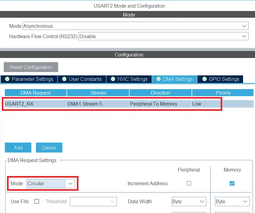
The DMA request is set for USART2_RX as we are receiving the data via the DMA. The data width is Byte as the UART transfers the data in bytes. The DMA mode is set as Circular.
The rest of the UART configuration is same as the previous tutorials with Baud Rate of 115200 with 8 data bits, 1 stop bit and no parity.
In Circular mode, the DMA never stops automatically, it is always in the receiving mode. Once all the required number of data bytes has been received, it automatically reset the receive counter to 0 and hence starts receiving again.
We still need to know the size of the incoming data. So the sender should first send 4 bytes of the size data followed by the data itself. If you are receiving larger data, you can change the length of the size data bytes, the rest of the code will change accordingly.
DMA Circular Mode Code
In the main function, we will set the DMA to receive 256 bytes of data. This data will contain the size bytes as well as the actual data itself.
uint8_t RxData[256];
uint8_t FinalBuf[4096];
int main()
{
  ....
  HAL_UART_Receive_DMA(&huart2, RxData, 256);
  ....
}The 256 bytes we requested contains the size data as well as the actual data. Once 128 bytes are received, the half received complete callback will be called. We can handle the received data inside this callback, while the DMA continues to receive the second half. Once all the 256 bytes are received, the receive complete callback will be called. Here we will process the data received in the second half of the buffer, while the DMA continues to receive the 3rd half. This process keep going on until the sender stops sending the data.
int HTC = 0, FTC = 0;
uint32_t indx=0;

int isSizeRxed = 0;
uint32_t size=0;

void HAL_UART_RxHalfCpltCallback(UART_HandleTypeDef *huart)
{
	if (isSizeRxed == 0)
	{
		size = ((RxData[0]-48)*1000)+((RxData[1]-48)*100)+((RxData[2]-48)*10)+((RxData[3]-48));  // extract the size
		indx = 0;
		memcpy(FinalBuf+indx, RxData+4, 124);  // copy the data into the main buffer/file
		memset(RxData, '\0', 128);  // clear the RxData buffer
		indx += 124;  // update the indx variable
		isSizeRxed = 1;  // set the variable to 1 so that this loop does not enter again
	}
	else
	{
		memcpy(FinalBuf+indx, RxData, 128);
		memset(RxData, '\0', 128);
		indx += 128;
	}
	HTC=1;  // half transfer complete callback was called
	FTC=0;
}The size data bytes are sent first so they are received in the first half of the received data. We will extract the size data, and write the rest of the data in the buffer/file inside the half received complete callback.
Since we use 4 bytes for the size field, the remaining 124 bytes (128 – 4) will pass to the buffer or file. At the same time, we update the indx variable to keep track of how many data bytes have already been written to the buffer or file.
This callback is called several times during the transfer, depending on how large data is. We only need to extract the size data in the first call, and for the rest, we will simply copy the 128 bytes to the buffer/file.
Similarly, the receive complete callback is called whenever all 256 bytes are received.
void HAL_UART_RxCpltCallback(UART_HandleTypeDef *huart)
{
	  memcpy(FinalBuf+indx, RxData+128, 128);
	  memset(RxData+128, '\0', 128);
	  indx+=128;
	  HTC=0;
	  FTC=1;
}Here we will simply copy the 128 bytes, from the second half of the buffer into the final buffer/file. Then clear the RxData buffer and update the indx variable.
Handling Partial Transfers in the Main Loop
Copying data using the half and complete callback is fine as long as the received data is in the multiple of 256. If not, then we have an issue. For example, if we receive 260 bytes, the half-receive callback will trigger first, followed by the receive-complete callback. However, the remaining 4 bytes will be stored at the beginning of the RxData buffer. Since these 4 bytes do not reach the 128-byte threshold, the half-receive callback will not trigger, and as a result, we might lose those 4 bytes.
To avoid this, we will manually check the received size with the size mentioned by the sender. If they are not equal, we will look where the remaining data is stored and then copy the data to our buffer/file.
Below is the code showing it in the while loop.
while (1)
{
  if (((size-indx)>0) && ((size-indx)<128))
  {
    if (HTC==1)
    {
      strcpy((char *)FinalBuf+indx, (char *)RxData+128);  // memcpy (FinalBuf+indx, RxData+128, (size-indx));
      indx = size;
      isSizeRxed = 0;
      HTC = 0;
      HAL_UART_DMAStop(&huart2);
      HAL_UART_Receive_DMA(&huart2, RxData, 256);
    }

  else if (FTC==1)
  {
     strcpy((char *)FinalBuf+indx, (char *)RxData);  // memcpy (FinalBuf+indx, RxData, (size-indx));
     indx = size;
     isSizeRxed = 0;
     FTC = 0;
     HAL_UART_DMAStop(&huart2);
     HAL_UART_Receive_DMA(&huart2, RxData, 256);
}We basically check if the difference between the size and indx variable is more than 0 and less than 128. This step is necessary because the size variable is calculated at the beginning, which means it starts with a large value. At the same time, the indx variable keeps increasing as more data bytes arrive. We choose the value 128 because if more than 128 bytes remain, either the half-complete or the complete callback will eventually trigger.
So if we do enter inside this condition, it means that neither of the callbacks are being called. The sender have stopped sending the data, and we have some extra data in either the first half or the second half of the RxData buffer.
We will verify which half contains the data by checking the HTC and FTC variables. If the HTC variable is set, it indicates that the half-receive callback has been triggered, which means the data is stored in the second half of the RxData buffer. In the same way, if the FTC variable is set, it indicates that the receive-complete callback has been triggered, and the data is stored in the first half of the RxData buffer.
We will simply copy the remaining data (size-indx) from the RxData buffer into the Final buffer/file. Then update the indx variable and reset the HTC/FTC variable. We also reset the isSizeRxed variable, so the system can correctly process the size of the new incoming data..
Now we need to start storing the received data from the beginning of the RxData buffer. But the DMA in circular mode will just store the data at the very next position. So we need to manually stop the DMA and call the function again to receive 256 bytes of data.
We discussed the case where extra bytes arrived and got stored in either the first half or the second half of the RxData buffer. But we could also receive data in the multiples of 128, so there will be no extra byte at all.
We also need to handle this scenario.
	  else if ((indx == size) && ((HTC==1)||(FTC==1)))
	  {
		  isSizeRxed = 0;
		  HTC = 0;
		  FTC = 0;
		  HAL_UART_DMAStop(&huart2);
		  HAL_UART_Receive_DMA(&huart2, RxData, 256);
	  }
}Here we will check if the size variable is equal to the indx variable. This situation can also occur at the beginning when both values are 0, or right after the previous if loop runs. To handle this, we add one more check to the condition and verify if either the HTC or FTC variable is set. This will confirm that the indx variable and the size variable are equal only after receiving all the data.
Inside this condition, we don’t need to copy any data since all the data has already been handled. We will simply reset the variables and start the DMA again.
Now we can receive the large data of any size and store in the buffer/file. Although we need to send the size first, followed by the data itself.
Circular Mode Result
The images below shows the data sent by the serial console and the data stored in the FinalBuf buffer.
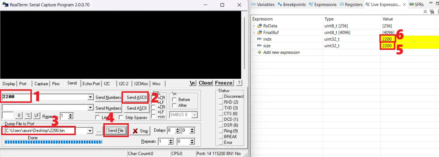
The numbers marked on the image are explained below.
- I am going to send a file of size 2200 bytes, therefore, I need to send the size first.
- Send the size data (“2200”).
- Select the file that contains the data.
- Send the file.
- The MCU has extracted the size data, and it is expecting 2200 bytes to be received.
- The indx variable is 2200, which means that the MCU has received 2200 bytes.
STM32 UART DMA Receive: Normal & Circular Mode — Video Tutorial
This video walks through STM32 UART DMA reception in both modes — configuring DMA Normal and Circular mode in CubeMX, implementing the size-preamble protocol, handling HAL_UART_RxCpltCallback and HAL_UART_RxHalfCpltCallback, managing partial transfers in the main loop, and verifying received data in the CubeIDE debugger.
STM32 UART DMA: Troubleshooting & FAQs
Common Errors & Fixes
Even with DMA, errors can occur. Here are some frequent problems and fixes:
Missing interrupt / callback issues
- Make sure DMA interrupts are enabled in STM32CubeMX.
- Check that
HAL_UART_RxCpltCallbackorHAL_UART_RxHalfCpltCallbackare properly implemented. - Verify that the
huart->Instancematches the correct USART peripheral.
Incorrect DMA configuration
- Ensure the DMA channel/stream matches the correct USART RX request.
- Use the correct data width (usually byte/8-bit).
- Confirm the DMA direction is Peripheral to Memory for UART RX.
Buffer overrun or incomplete transfers
- Overrun happens when the buffer is too small or processed too slowly.
- In Normal mode, if fewer bytes arrive than expected, the callback won’t trigger.
- In Circular mode, if the CPU doesn’t read data before DMA overwrites it, bytes will be lost.
Serial sender-side mismatches
- Mismatched baud rate, parity, or stop bits cause framing errors.
- Ensure both sender and STM32 UART settings match.
- If using modules (e.g., ESP8266, GPS), confirm their serial configuration first.
Frequently Asked Questions
Conclusion
In this tutorial we implemented both UART DMA receive modes on STM32. Normal mode is the right choice when the incoming frame size is known in advance — one HAL_UART_Receive_DMA() call, one callback, done. Circular mode handles everything else: continuous streams, files of arbitrary size, data that arrives in bursts — the half-complete and complete callbacks relay chunks into your final buffer while the DMA keeps running uninterrupted.
The trickiest part is the partial-transfer handling in the main loop. When data size is not an exact multiple of your DMA buffer, neither callback fires for the last few bytes. The HTC/FTC flag pattern in the while(1) loop catches this and copies the tail correctly before stopping and restarting the DMA.
In Part 5, we move to a cleaner approach to the same problem: UART IDLE line detection with DMA, which removes the need for a 4-byte size preamble entirely and handles variable-length frames using the hardware IDLE interrupt.
Download STM32 UART DMA Receive Project Files
Complete CubeIDE project with both DMA Normal Mode and Circular Mode examples — includes CubeMX config, size-preamble protocol, half/full transfer callbacks, and partial-transfer handling in the main loop. Free to download — support the work if it helped you.
Browse More STM32 UART Tutorials
STM32 UART Part 2 – Transmit using DMA & Interrupt
STM32 UART Part 3 – Receive Data in Blocking & Interrupt mode
STM32 UART Idle Line: Receive Data via Interrupt & DMA
STM32 UART Part 6 – Half-Duplex Communication (Single-Wire Mode)
STM32 UART Part 7 – How to use one-Wire Protocol



When using DMA for UART RX, one must never stop the DMA, or data will get lost. There is a race condition. The rule is that DMA must work all the time, however application must be able to read the data fast from the buffer.
I find very good explanation here
https://github.com/MaJerle/stm32-usart-uart-dma-rx-tx