Last Updated: April 14, 2026
Modbus TCP Protocol Explained: Frame Structure, MBAP Header, and Function Codes
This is the introductory post in the Modbus TCP series for STM32 microcontrollers.
Before we start writing any code, it is important to understand how the Modbus TCP protocol actually works. In this post, we will cover the structure of the Modbus TCP frame, explain every field in the MBAP header, and walk through a real example of a complete request and response exchange.
If you have followed the Modbus RTU series, a lot of this will feel familiar. The core logic is exactly the same. The only thing that changes is how the frame is constructed.
Modbus TCP vs Modbus RTU – Key Differences
In the Modbus RTU series, we covered how to configure the STM32 as both a Modbus master and a Modbus slave. We worked with holding registers, coils, input registers, and discrete inputs. All of that knowledge still applies here.
Modbus TCP uses the same function codes and the same data model as Modbus RTU. The internal working logic does not change. What changes is the transport layer — Modbus TCP runs over Ethernet and uses the TCP protocol instead of a serial UART connection.
What Changed in the Frame Structure?
Let us compare both RTU and TCP frame structures side by side.
Modbus RTU Frame:

Modbus TCP Frame:

Two things stand out:
- The address field is replaced by the MBAP header.
- There is no checksum. TCP already has its own built-in error checking, so we do not need to calculate a CRC.
The function code and data section remain exactly the same as in RTU. So if you are familiar with how function codes work, you already know that part.
Modbus TCP Frame Structure
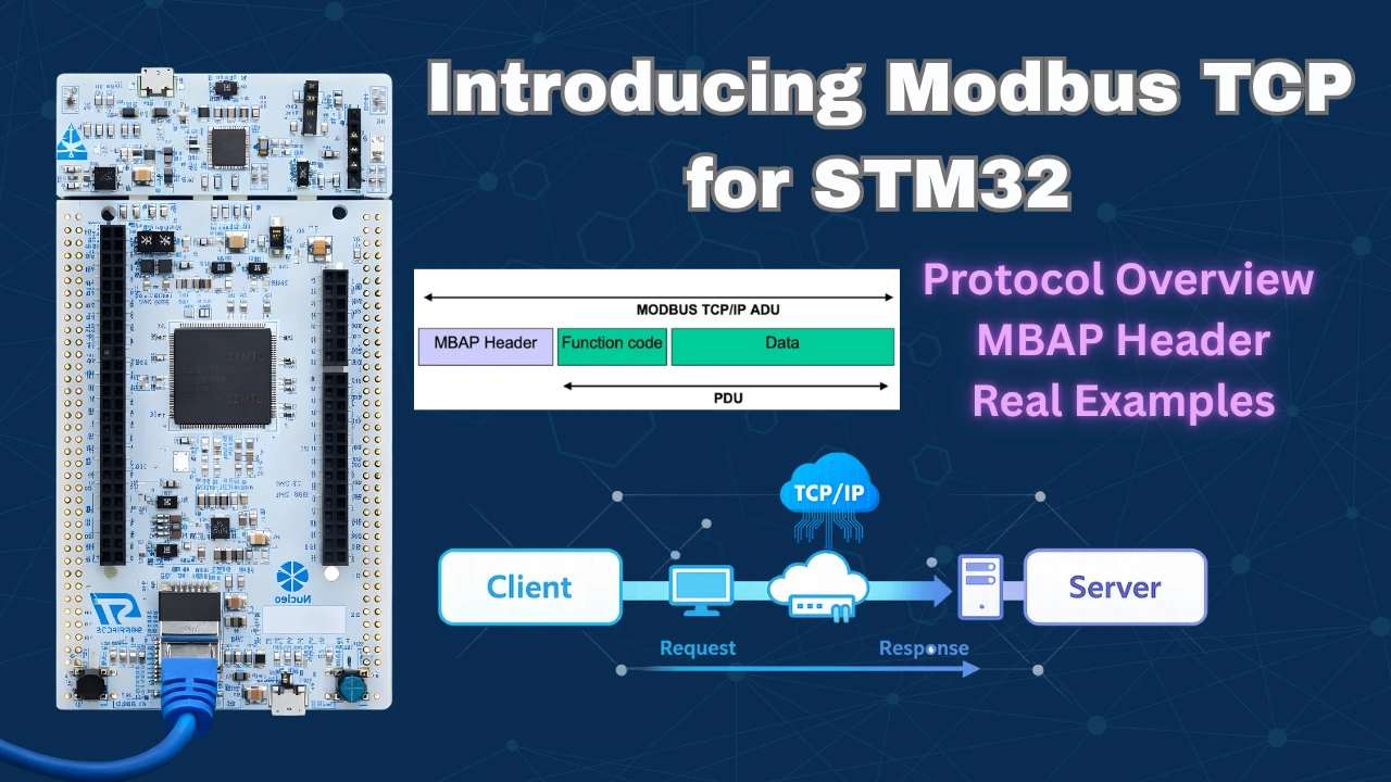
Every Modbus TCP message is built around a structure called the Application Data Unit, or ADU. This is the complete package that gets transmitted over TCP.
What is the Application Data Unit (ADU)?
The ADU contains everything needed to transmit a Modbus message over TCP. It has two main parts:
- The MBAP Header — which comes first and carries metadata about the transaction.
- The Protocol Data Unit (PDU) — which carries the actual function code and data.
Together, these two parts form the complete ADU that is sent over the network.

What is the Protocol Data Unit (PDU)?
The PDU is the inner part of the ADU. It consists of:
- 1 byte — Function Code (what operation to perform)
- N bytes — Data (parameters for that operation)

The PDU is identical to what we used in Modbus RTU. If the client wants to read coils, the function code and data bytes are constructed exactly the same way. The MBAP header is what makes it Modbus TCP.
The image below shows the complete Application Data Unit frame, along with the number of bytes occupied by each element.

Modbus TCP MBAP Header Explained
MBAP stands for Modbus Application Protocol. The header is 7 bytes long and sits at the beginning of every Modbus TCP frame. Let us go through each field.

All fields in the Modbus TCP frame are encoded in Big Endian format. This means the higher byte is sent first. We need to keep this in mind whenever we extract or combine multi-byte values from the frame.
Transaction Identifier
This is a 2-byte field. The client generates a unique ID for each request it sends. When the server sends back a response, it copies this exact value into its response without any changes. This allows the client to match each response to the correct request, especially when multiple transactions are happening.
Protocol Identifier
This is also 2 bytes. It is always set to 0x0000 for Modbus TCP communications. The server copies this value back into the response as-is, just like the Transaction Identifier. This field exists to allow future protocol extensions, but for standard Modbus TCP, it is always zero.
Length Field
This is a 2-byte field that tells the receiver how many bytes follow after this field. It counts the Unit Identifier byte plus all the bytes in the PDU.
The client and server each calculate their own length value independently:
- The client calculates the length based on the request data it is sending.
- The server recalculates the length based on the response data it is sending back.
So this field is not copied from the request — the server always creates a new value.
Unit Identifier
This is a 1-byte field. It works similarly to the Slave ID in Modbus RTU. It is most useful when there are multiple Modbus servers on the same network. A server can be configured to only respond to requests that carry its assigned Unit Identifier.
If we are connecting the client to just one server, this field does not matter much. We can set it to any value. The server copies this field back into the response.
How to Build a Modbus TCP Frame
Now let us put all of this together with a practical example. We will construct a Modbus TCP frame to read the status of 4 coils starting from address 0.
Constructing the Read Coils Request
We build the frame field by field:
Step 1 — Transaction Identifier (2 bytes): We set this to 1 for our first transaction. In Big Endian format, this is sent as 0x00 0x01.
Step 2 — Protocol Identifier (2 bytes): Always 0 for Modbus. Sent as 0x00 0x00.
Step 3 — Length Field (2 bytes): We count all the bytes that come after this field:
| Field | Size |
|---|---|
| Unit Identifier | 1 byte |
| Function Code | 1 byte |
| Starting Address | 2 bytes |
| Number of Coils | 2 bytes |
| Total | 6 bytes |
So the Length field is set to 0x00 0x06.
Step 4 — Unit Identifier (1 byte): We set this to 0x0A (10 in decimal).
Step 5 — Function Code (1 byte): To read coil status, we use Function Code 1: 0x01.
Step 6 — Starting Address (2 bytes): We want to read from address 0: 0x00 0x00.
Step 7 — Number of Coils (2 bytes): We want to read 4 coils: 0x00 0x04.
The complete request frame looks like this:

Understanding the Server Response
When the server receives this request, it processes it and sends back a response. The response follows the same structure — MBAP header followed by PDU.
The server’s MBAP header is mostly the same, but the Length field is recalculated based on the response data:
| Field | Size |
|---|---|
| Unit Identifier | 1 byte |
| Function Code | 1 byte |
| Byte Count | 1 byte |
| Coil Data | 1 byte |
| Total | 4 bytes |
So the server sets its Length field to 0x00 0x04.
The complete response frame:

The coil data (0x00) means all 4 coils are currently OFF. Each bit in the data byte represents one coil.
Modbus TCP Function Codes
The function codes in Modbus TCP are identical to those in Modbus RTU. Here are the ones we will use throughout this series:
| Function Code | Operation |
|---|---|
| 0x01 | Read Coil Status |
| 0x02 | Read Discrete Inputs |
| 0x03 | Read Holding Registers |
| 0x04 | Read Input Registers |
| 0x05 | Write Single Coil |
| 0x06 | Write Single Register |
| 0x0F | Write Multiple Coils |
| 0x10 | Write Multiple Registers |
| 0x11 | Read Slave ID |
We will use each of these in the hands-on videos throughout this series.
Modbus TCP Communication Example
Let us now look at a real communication example using the Simply Modbus TCP Client software. This is the same type of client application we used in the RTU series.
At the top of the interface, we set the following:

- Mode: TCP
- IP Address: The server’s IP address
- Port: 502 (this is the standard Modbus TCP port — all servers must listen on port 502)
- Slave ID: 10
- Function Code: 1 (Read Coils)
- First Coil Address: 10001 (the offset maps this back to address 0 on the server)
- Number of Coils: 4
Analyzing the Raw Request
Once we configure these parameters and click Send, the client generates and transmits the following bytes:

0x00 0x01 | 0x00 0x00 | 0x00 0x06 | 0x0A | 0x01 | 0x00 0x00 | 0x00 0x04Let us break this down:
0x00 0x01— Transaction ID, auto-generated by the client for this transaction.0x00 0x00— Protocol Identifier, always 0.0x00 0x06— Length field. Exactly 6 bytes follow after this field.0x0A— Unit Identifier (Slave ID = 10).0x01— Function Code 1, Read Coils.0x00 0x00— Starting address 0. The first coil address and the offset cancel each other out.0x00 0x04— Number of coils to read = 4.
Analyzing the Raw Response
The server processes the request and responds with the following bytes:

0x00 0x01 | 0x00 0x00 | 0x00 0x04 | 0x0A | 0x01 | 0x01 | 0x00Breaking it down:
0x00 0x01— Transaction ID, copied from the client request.0x00 0x00— Protocol Identifier, copied as-is.0x00 0x04— Length field. The server recalculated this — only 4 bytes follow.0x0A— Unit Identifier, copied from the request.0x01— Function Code 1, echoed back.0x01— Byte count. The actual coil data is 1 byte long.0x00— The coil data. All 4 coils are OFF (all bits are 0).
Output
The image below shows the Simply Modbus TCP Client after receiving the server response. The four coil values are displayed at the top right of the interface. All values are zero since the coils were set to OFF for this demonstration.

Modbus TCP Protocol Explained — Video Tutorial
This complete video tutorial explains how the Modbus TCP protocol works. You’ll learn about the ADU and PDU frame structure, how to construct the MBAP header, the difference between Modbus TCP and Modbus RTU, and how to analyze real request and response frames byte by byte.
Modbus TCP Protocol Explained – Frequently Asked Questions
Conclusion
In this tutorial, we covered the fundamentals of the Modbus TCP protocol. We started with the basic frame structure and compared it to Modbus RTU. We then went through every field in the MBAP header — the Transaction Identifier, Protocol Identifier, Length field, and Unit Identifier — and understood what each one does. We also walked through a complete real-world example, constructing a read coils request frame byte by byte and analyzing how the server builds its response.
The key thing to remember is that Modbus TCP uses the same function codes and data model as Modbus RTU. The only thing that changes is the frame structure. The MBAP header replaces the address field from RTU, there is no checksum since TCP handles error checking at the transport layer, and all fields are encoded in Big Endian format. All Modbus servers must listen on port 502.
In the next tutorial, we will move from theory to practice. We will configure the STM32 as a Modbus TCP slave, connect discrete inputs to its GPIO pins, and see how a Modbus master reads their real-time state over Ethernet.
