
Home ▸ Arduino ▸ Sensors Interfacing ▸
Updated On: April 30, 2026
MPU6050 Arduino I2C Tutorial: Wiring, Raw Data, Calibration & Code
The MPU6050 is a 6-axis IMU that combines a 3-axis accelerometer and 3-axis gyroscope on a single chip — making it one of the most capable and affordable motion sensors for Arduino projects. Whether you’re building a self-balancing robot, a gesture controller, or a drone stabilizer, the MPU6050 gives you accurate motion data over a simple 2-wire I2C interface.
In this tutorial, you’ll learn how to wire the MPU6050 to Arduino Uno/Nano/Mega, read raw accelerometer and gyroscope data directly from registers (no library needed), convert those raw values into g-force and degrees per second, and calibrate all six axes for clean, stable output. All code is written using Arduino’s Wire.h library with no external dependencies. A complete project download is available at the end.
If you’re working with other I2C sensors on Arduino, check out these related guides:
- ADXL345 Accelerometer with Arduino (I2C)
- BMP180 Pressure Sensor with Arduino
- BME280 Environmental Sensor with Arduino
- SHT21 Temperature & Humidity Sensor with Arduino
- DHT11 / DHT22 Sensors with Arduino
- HC-SR04 Ultrasonic Distance Sensor with Arduino
Browse the full Arduino Sensor Interfacing tutorial collection for more.
MPU6050 Overview & How It Works
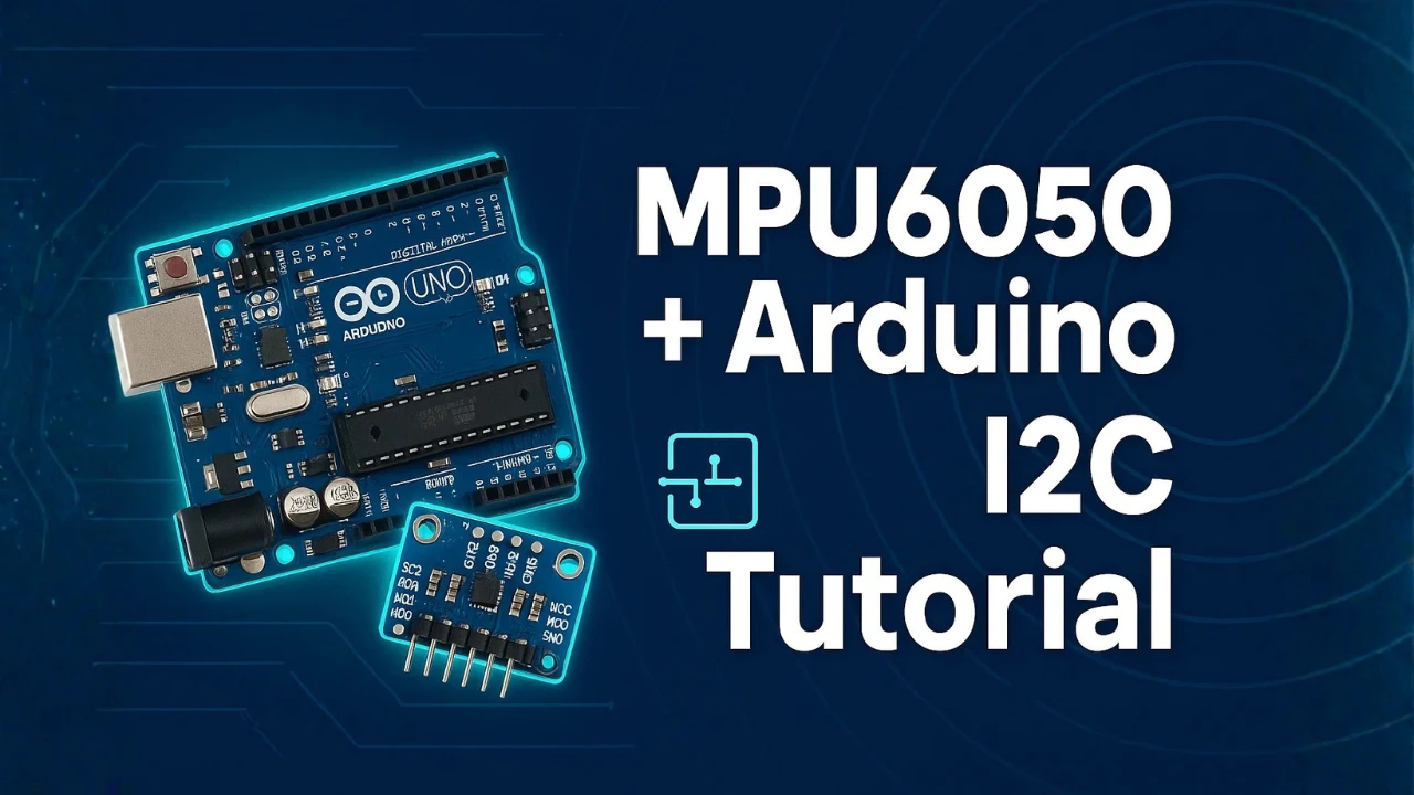
The MPU6050 is a popular motion-tracking sensor used in many Arduino and robotics projects. It comes with a 3-axis accelerometer and a 3-axis gyroscope, both packed inside one small chip. This makes it a complete 6-axis IMU sensor. It can measure tilt, motion, rotation, and orientation in real time. Because it works on the I2C interface, it is easy to connect and simple to use with Arduino.
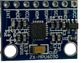
What Is the MPU6050? (6-Axis IMU Explained)
The MPU6050 combines two sensors:
- 3-axis accelerometer
Measures linear acceleration along X, Y, and Z axes.
Helps detect tilt, vibration, and movement. - 3-axis gyroscope
Measures rotation rate around X, Y, and Z axes.
Helps track angular motion and orientation.
Together, these six measurements allow you to track the exact movement of any object. This is why the MPU6050 is often used in drones, self-balancing robots, gaming controllers, and IoT devices.
Accelerometer vs Gyroscope — Key Differences
To understand the MPU6050, you must know how its two main sensors work:
- Accelerometer
Measures acceleration in three directions: X, Y, and Z.
It tells you how fast the sensor is moving in a straight line.
It can also measure the tilt angle because gravity affects its readings. - Gyroscope
Measures angular velocity around three axes.
It tells you how fast the sensor is rotating or turning.
It cannot detect tilt, but it tracks rotational motion very accurately.
Why the MPU6050 Is Popular in Arduino Projects
The MPU6050 is very common in Arduino projects because:
- It offers 6-axis motion tracking in a single compact module.
- It uses the simple I2C protocol, so only two wires are needed.
- It provides stable readings with a built-in Digital Motion Processor (DMP).
- It is cheap, easily available, and works on both 3.3V and 5V boards.
- It has a wide measurement range for both accelerometer and gyroscope.
Thanks to these advantages, makers use the MPU6050 in projects like self-balancing robots, gesture control, quadcopters, and wearable devices.
MPU6050 Pinout & Pin Functions
The image below shows the MPU6050 Pinout.
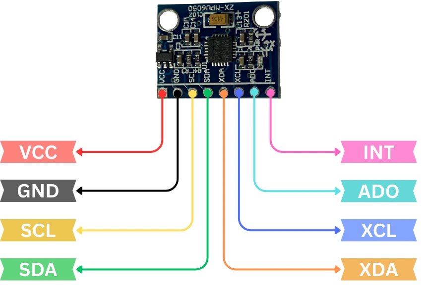
The pins and their functions are explained in the table below:
| Pin Name | Function | Description |
|---|---|---|
| VCC | Power Input | Provides power to the module. Supports 3.3V–5V on most breakout boards. |
| GND | Ground | Connects to Arduino ground. |
| SCL | I2C Clock | Serial Clock Line for I2C. Connect to A5 on Uno/Nano. |
| SDA | I2C Data | Serial Data Line for I2C. Connect to A4 on Uno/Nano. |
| INT | Interrupt | Used for motion interrupts or DMP features. Optional. |
| XDA | Aux Data | Auxiliary I2C data line for connecting extra I2C devices. Rarely used. |
| XCL | Aux Clock | Auxiliary I2C clock line. Rarely used. |
| ADO | Address Select | Changes I2C address from 0x68 (default) to 0x69 when pulled high. |
MPU6050 Arduino I2C Wiring & Connections
The MPU6050 uses the I2C communication protocol, which makes the connection very simple. You only need two data lines to connect it with any Arduino board. In this section, we will look at the components needed, the wiring diagram, and how the I2C address works. Once connected, you can start reading raw accelerometer and gyroscope data easily.
Required Components
You will need the following items:
- Arduino Uno / Nano / Mega
- MPU6050 Module
- Jumper Wires
- Breadboard (optional)
- USB Cable to power the Arduino
Wiring Diagram (Uno / Nano / Mega)
The wiring is very simple because MPU6050 works on I2C. The image below shows the wiring connection between MPU6050 and Arduino.
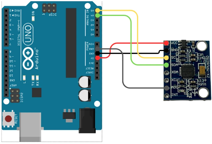
Here is the connection table:
| MPU6050 Pin | Arduino Uno / Nano Pin | Description |
|---|---|---|
| VCC | 5V or 3.3V | Power supply |
| GND | GND | Ground |
| SCL | A5 | I2C Clock |
| SDA | A4 | I2C Data |
| INT | (Optional) | Interrupt pin |
| ADO | GND | Sets I2C address to 0x68 |
For Arduino Mega, connect SDA → 20 and SCL → 21.
For Arduino Leonardo, connect to the dedicated SDA/SCL pins.
I2C Address — 0x68 vs 0x69
The MPU6050 communicates over the I2C bus using a 7-bit address.
It has two possible addresses:
- 0x68 → Default address (ADO pin LOW)
- 0x69 → Alternate address (ADO pin HIGH)
Most breakout boards keep ADO connected to GND, so the default address is 0x68. This is the address your Arduino will use to read and write data from the sensor.
If you ever need two MPU6050 sensors on the same I2C bus, simply pull the ADO pin HIGH on one module to change the address to 0x69.
MPU6050 Arduino Code: Read, Convert & Calibrate
Once your MPU6050 is connected to the Arduino, the next step is to read the raw sensor data. These raw values come directly from the sensor registers before any conversion or calibration. Understanding these values is important because you will later convert them into g-force and degrees per second. In this section, we will learn about the required registers and read raw data for both accelerometer and gyroscope.
MPU6050 Register Map Overview
The MPU6050 stores all accelerometer and gyroscope readings in specific registers. Each axis uses two registers (high byte + low byte). Here are the important ones:
| Sensor | Register Address | Description |
|---|---|---|
| Accelerometer X | 0x3B & 0x3C | High and Low bytes |
| Accelerometer Y | 0x3D & 0x3E | High and Low bytes |
| Accelerometer Z | 0x3F & 0x40 | High and Low bytes |
| Temperature | 0x41 & 0x42 | Raw temperature |
| Gyroscope X | 0x43 & 0x44 | High and Low bytes |
| Gyroscope Y | 0x45 & 0x46 | High and Low bytes |
| Gyroscope Z | 0x47 & 0x48 | High and Low bytes |
Before reading these registers, you must wake up the MPU6050 because it starts in sleep mode. To do that, write 0 to register 0x6B (PWR_MGMT_1).
Read Raw Accelerometer Data
Below is the code to read the RAW acceleration values from the MPU6050.
#include <Wire.h>

#define MPU_ADDR 0x68  // Default I2C address of MPU6050

int16_t AccX, AccY, AccZ;

void setup() {
  Wire.begin();               // Start I2C communication
  Serial.begin(9600);         // Start Serial Monitor

  // ----- MPU6050 Initialization -----
  Wire.beginTransmission(MPU_ADDR);
  Wire.write(0x6B);           // PWR_MGMT_1 register
  Wire.write(0x00);           // Wake up MPU6050 (set sleep = 0)
  Wire.endTransmission(true);

  // Set accelerometer range to ±2g (most stable)
  Wire.beginTransmission(MPU_ADDR);
  Wire.write(0x1C);           // ACCEL_CONFIG register
  Wire.write(0x00);           // ±2g range
  Wire.endTransmission(true);

  // Set sample rate (optional)
  Wire.beginTransmission(MPU_ADDR);
  Wire.write(0x19);           // SMPLRT_DIV register
  Wire.write(0x07);           // Sample rate = 1kHz / (7+1) = 125Hz
  Wire.endTransmission(true);

  Serial.println("MPU6050 Initialized for Raw Accelerometer Readings");
}

void loop() {
  // Request accelerometer registers starting from 0x3B
  Wire.beginTransmission(MPU_ADDR);
  Wire.write(0x3B);
  Wire.endTransmission(false);
  Wire.requestFrom(MPU_ADDR, 6, true);

  // Read raw data (16-bit signed)
  AccX = (Wire.read() << 8) | Wire.read();
  AccY = (Wire.read() << 8) | Wire.read();
  AccZ = (Wire.read() << 8) | Wire.read();

  Serial.print("AccX: "); Serial.print(AccX);
  Serial.print(" | AccY: "); Serial.print(AccY);
  Serial.print(" | AccZ: "); Serial.println(AccZ);

  delay(200);
}Code Explained (Accelerometer Section)
1. Initialization
- Wake up the sensor from sleep mode
- Set accelerometer range to ±2g for highest accuracy
- Set sample rate to 125Hz
This ensures stable and clean raw readings.
2. Reading Data
- Start reading from register 0x3B
- Read 6 bytes for X, Y, Z
- Combine high and low bytes into a 16-bit signed integer
3. Serial.print prints raw values directly to Serial Monitor.
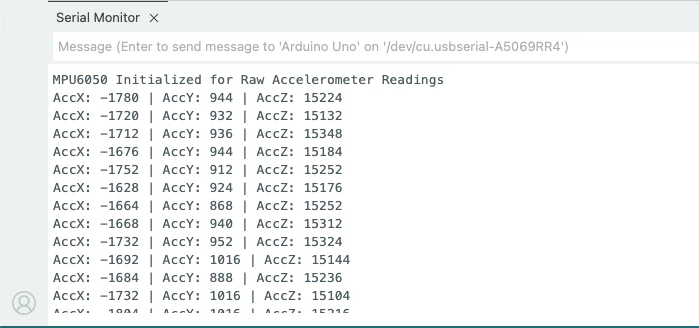
Output on the serial monitor
The image below shows the output of the code. The Raw values are displayed on the serial monitor.
Read Raw Gyroscope Data
Below is the code to read the RAW gyroscope values from the MPU6050.
#include <Wire.h>

#define MPU_ADDR 0x68

int16_t GyroX, GyroY, GyroZ;

void setup() {
  Wire.begin();
  Serial.begin(9600);

  // ----- MPU6050 Initialization -----
  Wire.beginTransmission(MPU_ADDR);
  Wire.write(0x6B);     // Wake up sensor
  Wire.write(0x00);
  Wire.endTransmission(true);

  // Configure gyroscope range to ±250 °/s
  Wire.beginTransmission(MPU_ADDR);
  Wire.write(0x1B);     // GYRO_CONFIG register
  Wire.write(0x00);     // ±250dps
  Wire.endTransmission(true);

  Serial.println("MPU6050 Initialized for Raw Gyroscope Readings");
}

void loop() {
  // Request gyroscope registers starting from 0x43
  Wire.beginTransmission(MPU_ADDR);
  Wire.write(0x43);
  Wire.endTransmission(false);
  Wire.requestFrom(MPU_ADDR, 6, true);

  GyroX = (Wire.read() << 8) | Wire.read();
  GyroY = (Wire.read() << 8) | Wire.read();
  GyroZ = (Wire.read() << 8) | Wire.read();

  Serial.print("GyroX: "); Serial.print(GyroX);
  Serial.print(" | GyroY: "); Serial.print(GyroY);
  Serial.print(" | GyroZ: "); Serial.println(GyroZ);

  delay(200);
}Code Explained (Gyro Section)
1. Initialization
- Wake up sensor
- Set gyroscope range to ±250°/s
This gives maximum precision for slow movements.
2. Reading Data
- Read registers starting from 0x43
- Fetch 6 bytes → X, Y, Z
- Combine into signed 16-bit values
3. Serial.print prints raw values directly to Serial Monitor.
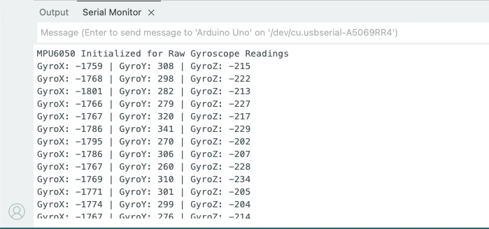
Output on the serial monitor
The image below shows the output of the code. The Raw values are displayed on the serial monitor.
Convert Raw Data to g and °/s
When you read data from the MPU6050, the accelerometer and gyroscope values are given as raw 16-bit numbers. These numbers don’t immediately tell you how much acceleration or rotation the sensor is experiencing.
To make the data useful, we convert accelerometer raw values into g-force (g) and gyroscope raw values into degrees per second (°/s). This section explains how these conversions work and provides the full code.
Convert Accelerometer Raw Data to g
The accelerometer measures acceleration along X, Y, Z axes.
The raw values depend on the scale you choose. The most commonly used scale is ±2g, where:
- LSB Sensitivity = 16384 LSB/g
This means:
g_value = raw_value / 16384.0Example:
If raw X = 8192 : X-axis acceleration = 8192 / 16384 = 0.5 g
Convert Gyroscope Raw Data to Degrees per Second
The gyroscope measures rotation around X, Y, Z axes.
With the default full-scale range ±250°/s:
- LSB Sensitivity = 131 LSB/(°/s)
So conversion is:
deg_per_sec = raw_value / 131.0Example:
If raw Z = 262 : Rotation = 262 / 131 = 2 °/s
Complete Code to Print Converted Values
Below is the full Arduino code to read Raw data and convert it to g and °/s.
#include <Wire.h>

#define MPU6050_ADDR 0x68

// MPU6050 Register Addresses
#define SMPLRT_DIV   0x19
#define CONFIG       0x1A
#define GYRO_CONFIG  0x1B
#define ACCEL_CONFIG 0x1C
#define PWR_MGMT_1   0x6B
#define ACCEL_XOUT_H 0x3B

void setup() {
  Serial.begin(9600);
  Wire.begin();

  // Wake up MPU6050
  Wire.beginTransmission(MPU6050_ADDR);
  Wire.write(PWR_MGMT_1);
  Wire.write(0x00);   // Clears sleep bit, enables the sensor
  Wire.endTransmission();

  // Sample Rate Divider
  Wire.beginTransmission(MPU6050_ADDR);
  Wire.write(SMPLRT_DIV);
  Wire.write(0x07);   // Sample rate = 1kHz / (7+1) = 125Hz
  Wire.endTransmission();

  // Digital Low Pass Filter (DLPF)
  Wire.beginTransmission(MPU6050_ADDR);
  Wire.write(CONFIG);
  Wire.write(0x03);   // DLPF = 44Hz
  Wire.endTransmission();

  // Gyroscope configuration
  Wire.beginTransmission(MPU6050_ADDR);
  Wire.write(GYRO_CONFIG);
  Wire.write(0x00);   // ±250°/s
  Wire.endTransmission();

  // Accelerometer configuration
  Wire.beginTransmission(MPU6050_ADDR);
  Wire.write(ACCEL_CONFIG);
  Wire.write(0x00);   // ±2g
  Wire.endTransmission();

  Serial.println("MPU6050 Initialized Successfully");
}

void loop() {
  int16_t raw_acc_x, raw_acc_y, raw_acc_z;
  int16_t raw_gyro_x, raw_gyro_y, raw_gyro_z;

  Wire.beginTransmission(MPU6050_ADDR);
  Wire.write(ACCEL_XOUT_H);
  Wire.endTransmission(false);
  Wire.requestFrom(MPU6050_ADDR, 14, true);

  // Reading accelerometer raw values
  raw_acc_x = (Wire.read() << 8) | Wire.read();
  raw_acc_y = (Wire.read() << 8) | Wire.read();
  raw_acc_z = (Wire.read() << 8) | Wire.read();

  // Reading temperature (not used)
  Wire.read(); Wire.read();

  // Reading gyroscope raw values
  raw_gyro_x = (Wire.read() << 8) | Wire.read();
  raw_gyro_y = (Wire.read() << 8) | Wire.read();
  raw_gyro_z = (Wire.read() << 8) | Wire.read();

  // Convert raw values to g
  float ax = raw_acc_x / 16384.0;
  float ay = raw_acc_y / 16384.0;
  float az = raw_acc_z / 16384.0;

  // Convert raw values to degrees per second
  float gx = raw_gyro_x / 131.0;
  float gy = raw_gyro_y / 131.0;
  float gz = raw_gyro_z / 131.0;

  // Print converted values
  Serial.print("Accel (g): ");
  Serial.print(ax); Serial.print(", ");
  Serial.print(ay); Serial.print(", ");
  Serial.println(az);

  Serial.print("Gyro (°/s): ");
  Serial.print(gx); Serial.print(", ");
  Serial.print(gy); Serial.print(", ");
  Serial.println(gz);

  Serial.println("----------------------------");
  delay(200);
}The image below shows the output of the code. The Acceleration values in g and Gyroscope values in °/s are printed on the console.
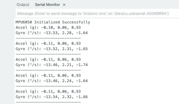
These values are obtained when the sensor is placed flat on the table. You can see both acceleration and gyroscope values have offset in them. Therefore we now need to calibrate the sensor.
Calibrate Accelerometer (3-Axis Offset)
Calibrating the MPU6050 is an important step before using the sensor for real measurements or motion-based projects. Even small factory offsets can cause inaccurate readings, drift, and unstable results.
The easiest calibration method is:
- Place MPU6050 perfectly still on a flat table.
- Read 200–500 samples from the accelerometer and gyroscope.
- Compute the average offset for each axis.
- Subtract this offset from future raw readings.
You only need to do this once unless you remount the sensor.
Code for Accelerometer Calibration
Below is the full Arduino code to calibrate the acceleration values in the MPU6050 sensor.
#include <Wire.h>

#define MPU6050_ADDR 0x68
#define ACCEL_XOUT_H 0x3B

long accX_offset = 0, accY_offset = 0, accZ_offset = 0;

void setup() {
  Serial.begin(9600);
  Wire.begin();

  // Wake up MPU6050
  Wire.beginTransmission(MPU6050_ADDR);
  Wire.write(0x6B);
  Wire.write(0);
  Wire.endTransmission();

  delay(1000);

  calibrateAccelerometer();
}

void loop() {
  // Nothing here - calibration prints automatically
}

void calibrateAccelerometer() {
  long sumX = 0, sumY = 0, sumZ = 0;

  Serial.println("Calibrating Accelerometer... Keep the sensor still.");

  for (int i = 0; i < 200; i++) {
    Wire.beginTransmission(MPU6050_ADDR);
    Wire.write(ACCEL_XOUT_H);
    Wire.endTransmission(false);
    Wire.requestFrom(MPU6050_ADDR, 6, true);

    int16_t rawX = (Wire.read() << 8) | Wire.read();
    int16_t rawY = (Wire.read() << 8) | Wire.read();
    int16_t rawZ = (Wire.read() << 8) | Wire.read();

    sumX += rawX;
    sumY += rawY;
    sumZ += rawZ;

    delay(5);
  }

  accX_offset = sumX / 200;
  accY_offset = sumY / 200;
  accZ_offset = (sumZ / 200) - 16384; // 1g correction (Z-axis)

  Serial.println("Accelerometer Calibration Done:");
  Serial.print("X Offset = "); Serial.println(accX_offset);
  Serial.print("Y Offset = "); Serial.println(accY_offset);
  Serial.print("Z Offset = "); Serial.println(accZ_offset);
}- The MPU6050 is first woken up by writing
0to register0x6B. - The code reads raw accelerometer values 200 times.
- Averages of these raw values become the offset.
- For Z-axis, 16384 is subtracted because this is the 1g value in ±2g mode.
- These offsets are printed for applying in future programs.
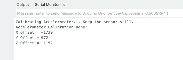
Output on the serial monitor
The image below shows the output of the code. The offsets in X, Y and Z axes are printed on the serial console.
Calibrate Gyroscope (3-Axis Offset)
Below is the full Arduino code to calibrate the gyroscope values in the MPU6050 sensor.
#include <Wire.h>

#define MPU6050_ADDR 0x68
#define GYRO_XOUT_H 0x43

long gyroX_offset = 0, gyroY_offset = 0, gyroZ_offset = 0;

void setup() {
  Serial.begin(9600);
  Wire.begin();

  // Wake up MPU6050
  Wire.beginTransmission(MPU6050_ADDR);
  Wire.write(0x6B);
  Wire.write(0);
  Wire.endTransmission();

  delay(1000);

  calibrateGyroscope();
}

void loop() {
  // Nothing here - calibration prints automatically
}

void calibrateGyroscope() {
  long sumX = 0, sumY = 0, sumZ = 0;

  Serial.println("Calibrating Gyroscope... Keep the sensor still.");

  for (int i = 0; i < 200; i++) {
    Wire.beginTransmission(MPU6050_ADDR);
    Wire.write(GYRO_XOUT_H);
    Wire.endTransmission(false);
    Wire.requestFrom(MPU6050_ADDR, 6, true);

    int16_t rawX = (Wire.read() << 8) | Wire.read();
    int16_t rawY = (Wire.read() << 8) | Wire.read();
    int16_t rawZ = (Wire.read() << 8) | Wire.read();

    sumX += rawX;
    sumY += rawY;
    sumZ += rawZ;

    delay(5);
  }

  gyroX_offset = sumX / 200;
  gyroY_offset = sumY / 200;
  gyroZ_offset = sumZ / 200;

  Serial.println("Gyroscope Calibration Done:");
  Serial.print("X Offset = "); Serial.println(gyroX_offset);
  Serial.print("Y Offset = "); Serial.println(gyroY_offset);
  Serial.print("Z Offset = "); Serial.println(gyroZ_offset);
}- The code reads raw gyroscope values 200 times.
- The averages of X, Y, and Z form the gyroscope offsets.
- Since the gyro should read 0°/s when stationary, these offsets represent the unwanted drift.
- These values must be subtracted from future gyro data.
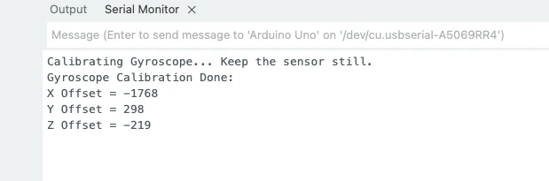
Output on the serial monitor
The image below shows the output of the code. The offsets in X, Y and Z axes are printed on the serial console.
Applying Offsets in Your Main Code
You will use the calibration values like this:
accX = rawAccX - accX_offset;
accY = rawAccY - accY_offset;
accZ = rawAccZ - accZ_offset;

gyroX = rawGyroX - gyroX_offset;
gyroY = rawGyroY - gyroY_offset;
gyroZ = rawGyroZ - gyroZ_offset;Final Combined Code (Calibrated + Converted)
The code below includes:
- MPU6050 initialization
- Calibration for accelerometer and gyroscope
- Reading raw values
- Applying offsets
- Converting data to g and °/s
- Printing everything on the Serial Monitor
#include <Wire.h>

// MPU6050 Registers
#define MPU6050_ADDR   0x68
#define ACCEL_XOUT_H   0x3B
#define GYRO_XOUT_H    0x43

// Calibration Offsets
long accX_offset = 0, accY_offset = 0, accZ_offset = 0;
long gyroX_offset = 0, gyroY_offset = 0, gyroZ_offset = 0;

// Scales
float accScale = 16384.0;   // For ±2g
float gyroScale = 131.0;    // For ±250 °/s

void setup() {
  Serial.begin(9600);
  Wire.begin();

  // Wake up MPU6050 – write 0 to power management register
  Wire.beginTransmission(MPU6050_ADDR);
  Wire.write(0x6B);
  Wire.write(0);
  Wire.endTransmission();

  delay(1000);

  calibrateAccelerometer();
  calibrateGyroscope();

  Serial.println("\nStarting Final Reading...\n");
}

void loop() {
  int16_t rawAccX, rawAccY, rawAccZ;
  int16_t rawGyroX, rawGyroY, rawGyroZ;

  // ------ Read Accelerometer ------
  Wire.beginTransmission(MPU6050_ADDR);
  Wire.write(ACCEL_XOUT_H);
  Wire.endTransmission(false);
  Wire.requestFrom(MPU6050_ADDR, 6, true);

  rawAccX = (Wire.read() << 8) | Wire.read();
  rawAccY = (Wire.read() << 8) | Wire.read();
  rawAccZ = (Wire.read() << 8) | Wire.read();

  // Apply offsets
  rawAccX -= accX_offset;
  rawAccY -= accY_offset;
  rawAccZ -= accZ_offset;

  // Convert to g
  float ax = rawAccX / accScale;
  float ay = rawAccY / accScale;
  float az = rawAccZ / accScale;

  // ------ Read Gyroscope ------
  Wire.beginTransmission(MPU6050_ADDR);
  Wire.write(GYRO_XOUT_H);
  Wire.endTransmission(false);
  Wire.requestFrom(MPU6050_ADDR, 6, true);

  rawGyroX = (Wire.read() << 8) | Wire.read();
  rawGyroY = (Wire.read() << 8) | Wire.read();
  rawGyroZ = (Wire.read() << 8) | Wire.read();

  // Apply offsets
  rawGyroX -= gyroX_offset;
  rawGyroY -= gyroY_offset;
  rawGyroZ -= gyroZ_offset;

  // Convert to degrees/sec
  float gx = rawGyroX / gyroScale;
  float gy = rawGyroY / gyroScale;
  float gz = rawGyroZ / gyroScale;

  // -------- Print Results --------
  Serial.print("Acc(g): ");
  Serial.print(ax); Serial.print(", ");
  Serial.print(ay); Serial.print(", ");
  Serial.println(az);

  Serial.print("Gyro(dps): ");
  Serial.print(gx); Serial.print(", ");
  Serial.print(gy); Serial.print(", ");
  Serial.println(gz);

  Serial.println("---------------------");
  delay(200);
}

// ---------------- Calibration Functions ---------------- //

void calibrateAccelerometer() {
  long sumX = 0, sumY = 0, sumZ = 0;

  Serial.println("Calibrating Accelerometer... Do not move!");

  for (int i = 0; i < 200; i++) {
    Wire.beginTransmission(MPU6050_ADDR);
    Wire.write(ACCEL_XOUT_H);
    Wire.endTransmission(false);
    Wire.requestFrom(MPU6050_ADDR, 6, true);

    sumX += (Wire.read() << 8) | Wire.read();
    sumY += (Wire.read() << 8) | Wire.read();
    sumZ += (Wire.read() << 8) | Wire.read();

    delay(5);
  }

  accX_offset = sumX / 200;
  accY_offset = sumY / 200;
  accZ_offset = (sumZ / 200) - 16384; // 1g adjustment

  Serial.println("Accelerometer Calibration Done.");
}

void calibrateGyroscope() {
  long sumX = 0, sumY = 0, sumZ = 0;

  Serial.println("Calibrating Gyroscope... Do not move!");

  for (int i = 0; i < 200; i++) {
    Wire.beginTransmission(MPU6050_ADDR);
    Wire.write(GYRO_XOUT_H);
    Wire.endTransmission(false);
    Wire.requestFrom(MPU6050_ADDR, 6, true);

    sumX += (Wire.read() << 8) | Wire.read();
    sumY += (Wire.read() << 8) | Wire.read();
    sumZ += (Wire.read() << 8) | Wire.read();

    delay(5);
  }

  gyroX_offset = sumX / 200;
  gyroY_offset = sumY / 200;
  gyroZ_offset = sumZ / 200;

  Serial.println("Gyroscope Calibration Done.");
}Serial Monitor Output & How to Verify Results
The image below shows the output of the code.
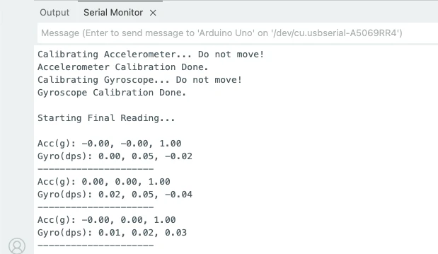
You can see in the image, after calibration, the acceleration values are precise. The acceleration in z-axis is 1g, whereas in x-axis and y-axis it is 0.
The gyroscope also shows values near to 0 as the sensor is kept stationary.
Meaning of the values:
- Accelerometer values near 0, 0, 1 indicate proper calibration.
- Gyroscope values near 0°/s show stable results.
- Small variations are normal because of sensor noise.
How to Verify the Working
You can easily check the sensor by:
1. Tilting the board
- If you tilt the sensor forward or sideways, the corresponding axis should move smoothly.
- No sudden jumps or drift.
2. Rotate the board
- Gyroscope values should increase only during movement.
- When still, they should return to zero.
MPU6050 Arduino Project Ideas & Applications
The MPU6050 is widely used in many Arduino projects because it provides both accelerometer and gyroscope data in a single compact module. Its fast response, low noise, and 6-axis sensing make it perfect for motion-based applications. Here are some of the most common and practical uses of the MPU6050 in Arduino projects.
Self-Balancing Robots
Self-balancing robots, such as two-wheel Segway-style robots, depend heavily on MPU6050.
The sensor provides pitch and roll angles, which help the robot stay upright by constantly correcting its position.
The gyroscope detects quick rotational changes while the accelerometer keeps the overall tilt stable. Together, they allow smooth and responsive balancing.
Gesture Control Systems
MPU6050 is also used in gesture-controlled projects such as:
- Controlling robots with hand movements
- Wireless mouse or cursor control
- Swipe, tilt, or rotation-based controls
The fast accelerometer and gyro readings make it easy to track hand gestures and map them to actions.
IMU Based Motion Tracking
In many DIY IMU (Inertial Measurement Unit) projects, the MPU6050 is the first choice.
It helps track movement and orientation over time.
Common examples include:
- VR head tracking
- Game controllers
- Drone flight stabilization
- Wearable motion trackers
Its combination of 3-axis acceleration + 3-axis rotation gives accurate and real-time movement detection, making it ideal for motion-tracking applications.
MPU6050 Arduino — Frequently Asked Questions
Conclusion
The MPU6050 is one of the best entry points into motion sensing for Arduino. It packs a 3-axis accelerometer and 3-axis gyroscope into a single compact module, communicates over I2C with just two wires, and delivers data accurate enough for real-world robotics and IoT applications.
In this tutorial, you went from wiring the sensor to reading raw register data, converting those values into useful units (g-force and °/s), and applying a 200-sample calibration routine to eliminate factory offsets from all six axes. The final combined sketch is ready to drop into any project requiring reliable motion input.
From here, you can build on this foundation by integrating complementary pitch/roll angle calculations, a Kalman or complementary filter, or pairing the MPU6050 with a magnetometer to get full 9-DOF orientation. Download the full project below and explore the Arduino Sensor Interfacing series for other sensors.
Download MPU6050 Arduino Project Files
Complete Arduino sketch with raw data reading, unit conversion, and full 3-axis accelerometer + gyroscope calibration. No external libraries required — uses Wire.h only. Free to download — support the work if it helped you.
Browse More Arduino Sensors Tutorials
SHT21 Arduino Tutorial: I2C Wiring, SHT2x Library, Serial & LCD Output
AHT20 Arduino Tutorial: I2C Wiring, Adafruit AHTX0 & OLED Display

SHT30 / SHT31 / SHT35 Arduino Tutorial: I2C Wiring, Code & LCD1602 Display
DS18B20 Arduino Tutorial: Single & Multiple Sensors, Serial & OLED Output
BMP180 Arduino Tutorial: I2C Wiring, Temperature, Pressure, Altitude & LCD1602

Subscribe
Login
0 Comments
Newest

