
Home ▸ Arduino ▸ Core Tutorials ▸
Updated On: May 28, 2026
Arduino ADC and analogRead() Explained: Complete Guide with Examples
Most Arduino sensors, like potentiometers, LDRs, temperature sensors, microphones output a voltage that changes continuously. analogRead() is the function that brings that voltage into your code as a number you can actually use.
To use it well, you need to understand what happens underneath: how the ADC converts voltage to a digital value, what the reference voltage does to your readings, and why a 10-bit ADC gives you 1024 steps and not 1000.
In this guide, you will learn:
- How the Arduino ADC works internally
- What
analogRead()returns and how to convert it back to volts - How reference voltage affects measurement accuracy
- How fast the ADC can sample
- How to read analog sensors reliably with working code examples
This is part of the Arduino Core Tutorials series. If you are new to Arduino I/O, start with these first:
- digitalWrite() and digitalRead()
- PWM and analogWrite()
- delayMicroseconds()
- External interrupts
- UART serial communication
How ADC Works
The ADC (Analog-to-Digital Converter) is a built-in feature that lets the Arduino read analog signals, like the output from a sensor. The ADC converts those voltages into digital numbers so your code can process them.
Without the ADC, the Arduino cannot read most sensors. Analog signals can take any value within a range, for example 0V to 5V. The microcontroller, however, only understands discrete values. The ADC acts as the bridge between the two.
This conversion process divides the voltage range into equal steps. Each step is assigned a digital value. The higher the resolution, the more precise the conversion.
Why Arduino Needs an ADC
Most sensors in Arduino projects output analog voltages:
- A temperature sensor outputs a voltage proportional to temperature.
- A light sensor (LDR) changes resistance with light, producing different voltages.
- A potentiometer provides a variable voltage depending on its position.
The ADC converts those voltages into numbers your code can use in calculations, display on a screen, or use to control outputs like motors or LEDs.
How Voltage Becomes a Number
The Arduino measures the voltage on an analog pin and maps it to a number between 0 and 1023 (for a 10-bit ADC like the Arduino UNO). The conversion depends on the reference voltage (VREF), which sets the maximum readable voltage — usually 5V or 3.3V depending on the board.
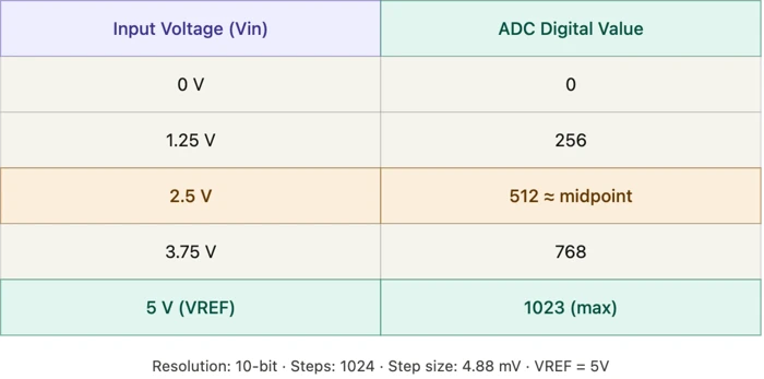
With a 5V reference:
- 0V → digital value 0
- 2.5V → digital value 512
- 5V → digital value 1023
10-Bit Resolution on Arduino UNO
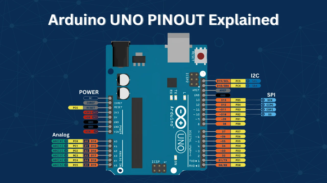
The Arduino UNO uses the ATmega328P microcontroller, which has a built-in 10-bit ADC. It reads analog signals on six pins (A0–A5) and converts voltages between 0V and 5V into values from 0 to 1023.
The term “10-bit” means the ADC divides the voltage range into 2¹⁰ = 1024 discrete levels. Each level represents a small voltage difference called the step size:
Step size = 5V ÷ 1024 = 4.88 mV per stepThis means the Arduino can detect voltage changes as small as 4.88 millivolts. More bits means finer and more accurate readings.
ADC Conversion Formula
When you apply a voltage to an analog pin, the ADC determines which digital step it corresponds to. The conversion formula is:
Where:
VREF= reference voltage (usually 5V or 3.3V)n= ADC resolution (10 bits for Arduino UNO)
Example with 5V reference:
- Vin = 0V → ADC value = 0
- Vin = 2.5V → ADC value = (2.5/5) × 1023 = 511.5 ≈ 512
- Vin = 5V → ADC value = (5/5) × 1023 = 1023
ADC Reference Voltage (VREF)
The reference voltage defines the maximum voltage the ADC can measure. Any voltage equal to VREF produces the highest possible ADC value — 1023 on a 10-bit ADC. Choosing the right reference voltage directly affects accuracy and precision.
Default, Internal, and External Reference Options
By default, the Arduino uses its operating voltage as the reference:
- 5V on 5V boards such as Arduino UNO and Mega.
- 3.3V on 3.3V boards such as Arduino Due, Nano 33, or MKR series.
Arduino also provides internal and external reference options:
- DEFAULT — uses the operating voltage (5V or 3.3V depending on the board).
- INTERNAL — uses an internal voltage reference, typically 1.1V on UNO or 2.56V on some ATmega chips.
- EXTERNAL — lets you connect your own reference voltage to the AREF pin.
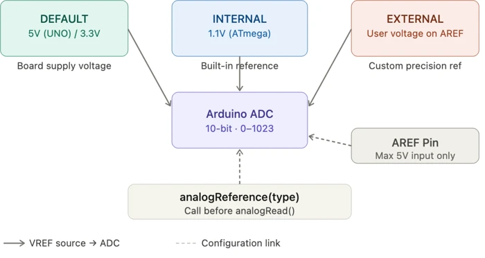
Using an internal or external reference helps when working with low-voltage sensors or when you need stable readings that are not affected by power supply variations.
How to Change VREF with analogReference()
Use analogReference() to select which reference voltage the ADC should use:
analogReference(type);Example:
analogReference(INTERNAL);   // Use the internal 1.1V reference
analogReference(DEFAULT);    // Use the default 5V or 3.3V reference
analogReference(EXTERNAL);   // Use external voltage on the AREF pin
Note:
When using EXTERNAL, connect a stable reference voltage to the AREF pin before calling analogReference(EXTERNAL). Never apply more than 5V to AREF.
How Reference Voltage Affects Accuracy
A smaller VREF gives you a smaller step size — meaning finer resolution for low-voltage signals.
- At VREF = 5V → each step = 4.88 mV (5V ÷ 1024)
- At VREF = 1.1V → each step = 1.07 mV (1.1V ÷ 1024)
A lower reference voltage gives more precise readings of small signals. However, if the input voltage exceeds the reference voltage, the ADC outputs the maximum value (1023). Choose VREF based on your sensor’s output range.
ADC Speed and Analog Input Pins
The ADC speed determines how fast the Arduino converts an analog signal into a digital value. This depends on the ADC clock frequency and conversion time. Understanding ADC timing matters for applications that need fast or frequent readings — such as signal processing or real-time monitoring.
Default Clock and Conversion Time
On the Arduino UNO, the ADC uses a clock derived from the 16 MHz system clock divided by a prescaler. The default prescaler is 128:
ADC Clock = 16 MHz ÷ 128 = 125 kHzEach conversion takes approximately 13 ADC clock cycles:
Conversion Time = 13 × (1 ÷ 125 kHz) ≈ 104 microsecondsThis gives roughly 9,600 to 10,000 ADC readings per second under default settings.
Sampling Rate
The sampling rate is the inverse of the conversion time:
Sampling Rate = 1 ÷ 104 µs ≈ 9,600 samples/second (9.6 kSPS)You can increase the sampling rate by reducing the prescaler. This raises the ADC clock frequency but slightly reduces accuracy:
- At 200 kHz ADC clock → conversion time ≈ 65 µs → ~15.4 kSPS
Running the ADC too fast causes noisy or unstable readings. Balance speed and precision based on your project’s needs.
How to Increase ADC Speed Safely
Adjust the prescaler in the ADC control register to increase speed. Common prescaler values: 2, 4, 8, 16, 32, 64, 128.
| Prescaler | ADC Clock | Speed | Accuracy |
|---|---|---|---|
| 128 (default) | 125 kHz | ~10,000 SPS | Full accuracy |
| 64 | 250 kHz | ~20,000 SPS | Slight loss |
| 32 | 500 kHz | ~40,000 SPS | Reduced |
For reliable 10-bit conversions, keep the ADC clock below 200 kHz. Going beyond that leads to inaccurate or fluctuating results.
Analog Input Pins by Board
Different Arduino boards have different numbers of analog pins and reference voltages:
| Board | Analog Pins | ADC Resolution | Reference Voltage |
|---|---|---|---|
| Arduino UNO | A0–A5 (6 pins) | 10-bit | 5V |
| Arduino Nano | A0–A7 (8 pins) | 10-bit | 5V |
| Arduino Mega | A0–A15 (16 pins) | 10-bit | 5V |
| Arduino Leonardo | A0–A11 (12 pins) | 10-bit | 5V |
| Arduino Due | A0–A11 (12 pins) | 12-bit | 3.3V |
| Arduino MKR Series | A0–A6 (7 pins) | 12-bit | 3.3V |
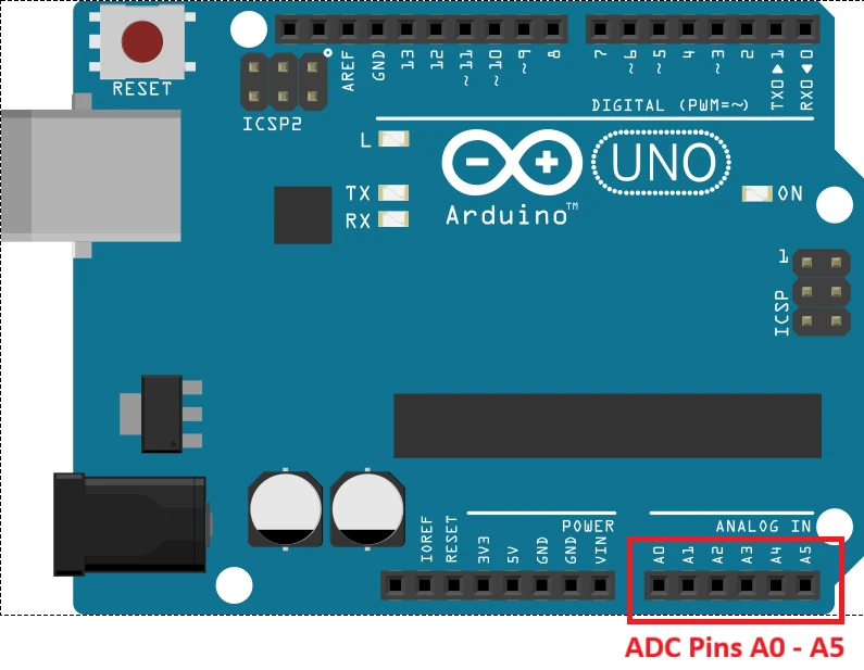
All analog pins work the same way and are read using analogRead().
Connecting Sensors to Analog Pins
You can connect any device that outputs a varying voltage to an analog pin — potentiometers, LDRs, temperature sensors, sound sensors, flex sensors, and more.
To connect a sensor:
- Connect the sensor’s
VCCpin to the Arduino’s5Vor3.3Vsupply. - Connect the sensor’s
GNDpin to ArduinoGND. - Connect the sensor’s output pin to one of the analog input pins (A0–A5).
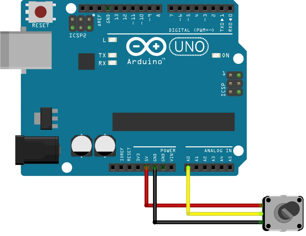
Once connected, use analogRead() to get a digital value representing the input voltage.
Safe Input Voltage Range
Each analog pin can measure voltages between 0V and the board’s VREF:
- 0V to 5V for 5V boards (UNO, Mega, Nano).
- 0V to 3.3V for 3.3V boards (Due, MKR series).
Note:
Applying a voltage higher than VREF — for example, more than 5V on a UNO — can damage the ADC or the entire microcontroller. Always keep sensor output within the board’s safe input range.
analogRead() Function
analogRead() reads the voltage from an analog pin and converts it to a digital value using the ADC. It is one of the most commonly used functions when working with sensors and variable inputs.
When you call analogRead(), the Arduino measures the voltage on the specified pin and returns a number between 0 and 1023 on 10-bit boards like the UNO.
Syntax and Parameters
analogRead(pin);The function takes a single parameter, the analog pin you want to read.
Example:
int sensorValue = analogRead(A0);This reads the voltage at pin A0 and stores it in sensorValue.
Return Values and Voltage Conversion
analogRead() returns an integer:
- 10-bit ADC (UNO, Mega, Nano): 0 to 1023
- 12-bit ADC (Due, MKR boards): 0 to 4095
To convert the returned value back to voltage:
Example for Arduino UNO with 5V reference:
float voltage = (sensorValue * 5.0) / 1023.0;Speed and Performance
On the Arduino UNO, a single analogRead() call takes approximately 100 microseconds, allowing around 10,000 readings per second. This is set by the default ADC clock of 125 kHz (16 MHz system clock divided by prescaler 128).
If your project needs faster readings, you can increase the ADC speed by changing the prescaler. Keep in mind that higher speed reduces accuracy due to less sampling time.
| Prescaler | Speed | Accuracy |
|---|---|---|
| 128 (default) | ~10,000 SPS | Accurate |
| 64 | ~20,000 SPS | Slightly less precise |
| 32 | ~40,000 SPS | Reduced accuracy |
For most projects, the default sampling rate gives the best balance of speed and accuracy.
Practical Examples
Now that you understand how analogRead() works, let us look at two working examples.
Example 1: Read a Potentiometer and Print Voltage to Serial
This example reads the voltage from a potentiometer on A0, converts it to volts, and prints both the raw ADC value and the voltage to the Serial Monitor.
Wiring
Connect the potentiometer wiper to A0, one outer pin to 5V, and the other outer pin to GND.
Code
int sensorPin = A0;      // Analog pin connected to potentiometer
int sensorValue = 0;     // Stores raw ADC value
float voltage = 0.0;     // Stores converted voltage

void setup() {
  Serial.begin(9600);
  Serial.println("Arduino ADC Reading Example");
}

void loop() {
  sensorValue = analogRead(sensorPin);               // Read ADC value (0–1023)
  voltage = (sensorValue * 5.0) / 1023.0;           // Convert to voltage

  Serial.print("Raw ADC Value: ");
  Serial.print(sensorValue);
  Serial.print("   Voltage: ");
  Serial.print(voltage);
  Serial.println(" V");

  delay(100);
}How it works:
analogRead()reads the potentiometer voltage and returns a value from 0 to 1023.- We scale that value to the 5V reference to get the actual voltage.
Serial.print()displays the readings in real time on the Serial Monitor.
Output
The GIF below shows the output of the above code. The ADC data read from the potentiometer is converted to voltage. It is then logged back to the serial console.

Example 2: Control LED Brightness with a Potentiometer
This example reads the potentiometer value and uses it to control LED brightness by combining analogRead() with analogWrite().
Wiring
Connect the potentiometer to A0 as before. Connect the LED through a 220Ω resistor to pin D9.

Code
int potPin = A0;     // Potentiometer on A0
int ledPin = 9;      // LED on pin 9 (PWM-capable)
int potValue = 0;    // Raw potentiometer reading
int ledValue = 0;    // Mapped PWM value

void setup() {
  pinMode(ledPin, OUTPUT);
  Serial.begin(9600);
  Serial.println("LED Brightness Control");
}

void loop() {
  potValue = analogRead(potPin);                       // Read potentiometer (0–1023)
  ledValue = map(potValue, 0, 1023, 0, 255);          // Map to PWM range (0–255)
  analogWrite(ledPin, ledValue);                       // Set LED brightness

  Serial.print("Potentiometer: ");
  Serial.print(potValue);
  Serial.print("   LED Brightness (PWM): ");
  Serial.println(ledValue);

  delay(100);
}How it works:
- The potentiometer acts as a variable voltage divider, producing 0V to 5V.
analogRead()converts that voltage to a value between 0 and 1023.map()scales the range to 0–255 to match the PWM range used byanalogWrite().analogWrite()adjusts LED brightness by varying the duty cycle.
Output
The GIF below shows the output of the above code. The ADC data read from the potentiometer is converted to voltage. It is then fed to the LED, whose brightness varies according to the voltage.

This example demonstrates how analogRead() and analogWrite() work together to convert analog input into a controllable digital output, forming the basis for many analog control projects in Arduino.
Note:
Always connect your LED through a 220Ω resistor to protect it from excessive current.
Tips for Accurate ADC Readings
Getting reliable analog readings requires attention to a few key factors. Noise, fluctuating voltages, and incorrect reference settings can all cause inaccurate measurements.
Reduce Noise and Fluctuations
Electrical noise from motors, relays, or nearby electronics can affect ADC readings. To reduce it:
- Keep analog signal wires short and away from high-current wires.
- Add a 0.1 µF decoupling capacitor near the sensor or analog input pin.
- Use shielded cables for sensitive sensors where possible.
Use the Right Reference Voltage
A stable and appropriate VREF improves accuracy:
- Use DEFAULT for general-purpose measurements (5V or 3.3V).
- Use INTERNAL or EXTERNAL for precise or low-voltage measurements.
- Avoid fluctuating supply voltages — they directly affect ADC output.
Average Multiple Readings
Small fluctuations and noise can be smoothed by averaging multiple readings:
long sum = 0;
for (int i = 0; i < 10; i++) {
  sum += analogRead(A0);
}
int averageValue = sum / 10;Averaging stabilizes readings and makes your sensor data more consistent.
Arduino ADC and analogRead(): FAQ
Conclusion
The Arduino ADC is doing more work than most beginners realize. Every time you call analogRead(), the hardware samples the input voltage, compares it against the reference, divides the range into 1024 steps, and returns the closest integer — all in about 100 microseconds. Understanding that process means you can predict exactly what value you'll get for any input voltage, choose the right reference for your sensor, and know when averaging or noise filtering is necessary.
The two most important things to get right are the reference voltage and noise control. A mismatched reference gives you a compressed or clipped reading range. Noise from motors, relays, or long unshielded wires introduces jitter that averaging can partially fix but hardware decoupling fixes better.
From here, the direct next step is PWM and analogWrite() — the LED brightness example in this tutorial already shows how the two work together, but the PWM guide covers frequency, timer registers, and multi-channel control in full. If you're building a sensor project that needs to send data to a computer or another microcontroller, UART serial communication is what connects analogRead() output to the outside world. And if you need the sensor reading to trigger an action immediately rather than being polled inside loop(), external interrupts is the right approach.
Download Arduino ADC and analogRead() Project Files
Complete Arduino sketches for reading a potentiometer with analogRead(), printing voltage to Serial Monitor, and controlling LED brightness with analogWrite() — tested and ready to upload. Free to download — support the work if it helped you.
Browse More Arduino Core Tutorials
Arduino Nano Pinout – Complete Guide with Diagram
Arduino digitalWrite() and digitalRead(): Complete Guide with Examples
Arduino UART Tutorial: Serial Communication, Send, Receive & LED Control
Arduino I2C Tutorial: Wire Library, Master/Slave, Scanner & Troubleshooting
Arduino delayMicroseconds() Tutorial: Precise Timing, Pulses & Alternatives

Subscribe
Login
0 Comments
Newest

