
Home ▸ Arduino ▸ Core Tutorials ▸
Updated On: October 18, 2026
Arduino Nano Pinout: Complete Guide with Diagram
The Arduino Nano uses the same ATmega328P chip as the Arduino UNO, but it comes in a board that is less than half the size and plugs directly into a breadboard. The pins sit close together on two narrow rows, and a few of them behave differently from the UNO, which makes it easy to wire a project incorrectly. The Nano has eight analog inputs instead of six, and two of them cannot be used as digital pins.
This guide covers all 30 pins of the Arduino Nano in the order you will use them. For each group, it explains what the pins do, how to use them in a sketch and which electrical limits apply. Wherever the Nano differs from the UNO, the difference is pointed out. A full reference table is included at the end.
The Nano shares most of its behavior with the UNO, so the Arduino UNO pinout guide is a useful companion for the details that are identical. Once you know the pins, the Arduino Core Tutorials show how to use GPIO, ADC, UART, I2C, SPI, PWM and interrupts in code.
This guide covers the classic Arduino Nano with the ATmega328P, including the common clones. The Nano Every and the Nano 33 boards use different microcontrollers and have different pin functions, so their pinouts do not match this page.
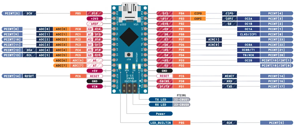
Table of contents
- Arduino Nano Pinout: Complete Guide with Diagram
- Arduino Nano Specifications
- Arduino Nano Pinout Diagram
- Arduino Nano Power Pins
- Arduino Nano Digital Pins
- Arduino Nano PWM Pins
- Arduino Nano Interrupt Pins
- Arduino Nano Analog Pins
- Arduino Nano UART Pins
- Arduino Nano I2C Pins
- Arduino Nano SPI Pins
- Arduino Nano Timer and Input Capture Pins
- Arduino Nano vs Arduino UNO
- Arduino Nano Pinout Table
- Conclusion
Arduino Nano Specifications
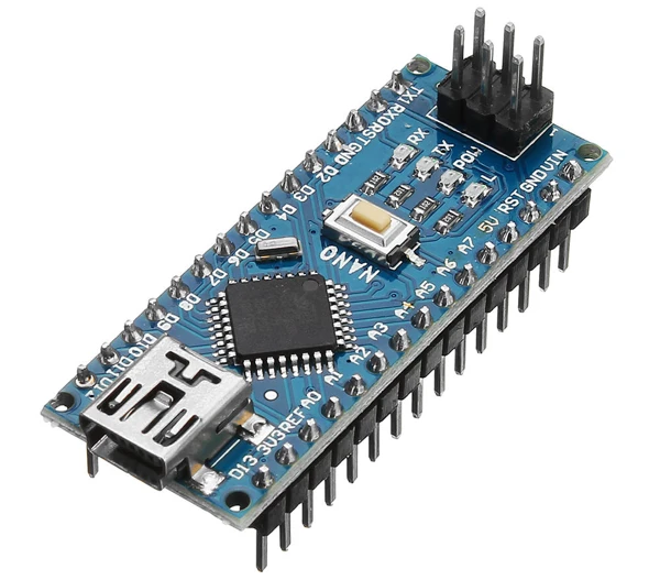
The Arduino Nano is a compact board built around the ATmega328P microcontroller, which is the same chip that the Arduino UNO uses. The board measures 45 mm by 18 mm, and its two rows of header pins fit directly into a breadboard. Power and programming come through the USB port on one end, and the board has no DC jack.
| Specification | Detail |
|---|---|
| Microcontroller | ATmega328P |
| Clock speed | 16 MHz |
| Flash memory | 32 KB (0.5 KB or 2 KB used by the bootloader, depending on its version) |
| SRAM | 2 KB |
| EEPROM | 1 KB |
| Operating voltage | 5 V |
| Input voltage (VIN) | 7 V to 12 V recommended, 6 V to 20 V limits |
| Digital I/O pins | 14 (D0 to D13) |
| Analog input pins | 8 (A0 to A7) |
| PWM pins | 6 (D3, D5, D6, D9, D10, D11) |
| Maximum current per I/O pin | 40 mA absolute maximum, 20 mA recommended |
| Board size | 45 mm × 18 mm |
| USB connector | Mini-B on the original board, Micro-USB or USB-C on many clones |
The extra analog pins A6 and A7 are the main difference from the UNO, and the analog section below explains how they work.
Arduino Nano Pinout Diagram
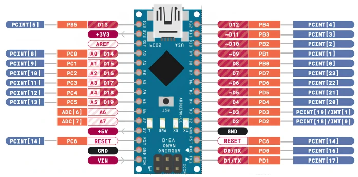
The diagram below shows all 30 pins of the Nano. Keep it open in a second tab while you read the sections that follow, because each section uses the same labels.
The pins fall into four groups, and the guide follows the same order.
- The power pins supply the board and external parts.
- The digital I/O pins read and write HIGH and LOW signals.
- The analog pins measure voltages from 0 V to 5 V.
- The communication pins carry UART, I2C and SPI data.
Arduino Nano Power Pins
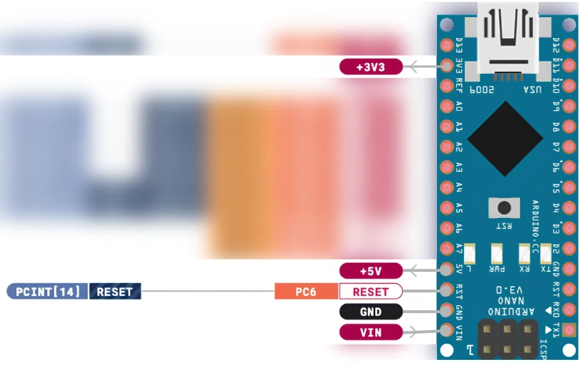
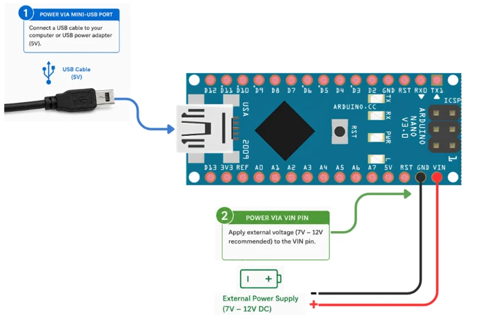
The power pins sit along the edges of the board. They let you supply the Nano from an external source and also let you power small sensors and modules from the board.
VIN Pin
The VIN pin accepts an external supply when you are not using USB. The board tolerates 6 V to 20 V, and the recommended range is 7 V to 12 V. The input passes through a linear voltage regulator, which turns the extra voltage into heat, so a high VIN makes the regulator hot. A 9 V battery or a 7.5 V adapter is a good choice.
5V Pin
The 5V pin carries the regulated 5 V rail. You can use it to power sensors and modules that need 5 V. When the board runs from USB, the available current is limited to about 500 mA by the USB port. When it runs from VIN, the limit depends on the regulator and on how much heat it can dissipate. Motors and other high-current loads need their own supply.
3.3V Pin
On the original Nano, the 3.3V pin is supplied by the USB-to-serial chip (FT232RL), and it can provide about 50 mA. That is enough for small sensors and modules, but not for anything larger. Many clones use a different USB chip, so the current on this pin can differ, and some clones provide no 3.3 V output at all. Check the specification of your board before you depend on it.
GND Pins
The Nano has two GND pins, one on each header row, and they are connected together inside the board. Every external module must share its ground with the Nano, because signals are measured against that common reference.
RESET Pin
Pulling the RESET pin LOW restarts the microcontroller, in the same way as the reset button. Other circuits use this pin when they need to restart the Nano from outside.
Power Pin Rules
- Keep VIN between 7 V and 12 V for reliable operation.
- The Nano selects between USB and VIN automatically, but you should avoid feeding a separate 5 V supply into the 5V pin while USB is connected.
- Do not draw more than about 50 mA from the 3.3V pin.
- Connect the ground of every external circuit to a GND pin of the Nano.
Arduino Nano Digital Pins
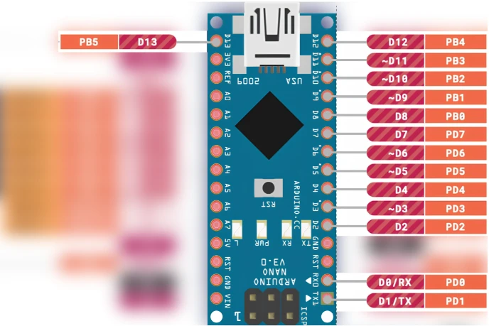
The Nano has 14 digital pins, labeled D0 to D13. You set each pin as an input or an output with pinMode(), and you control it with digitalWrite() and digitalRead(). The digitalRead() and digitalWrite() tutorial explains both functions with examples.
How Digital Pins Work
In output mode, a HIGH pin drives 5 V and a LOW pin drives 0 V. In input mode, the ATmega328P reads a voltage above about 3 V as HIGH and a voltage below about 1.5 V as LOW. A voltage between those two levels gives an unreliable result, so an input should never be left floating. A pull-up or pull-down resistor, or the internal pull-up enabled with INPUT_PULLUP, keeps the pin at a defined level.
The absolute maximum current of a pin is 40 mA, but 20 mA is a safer working value. The total current through all I/O pins together should stay below 200 mA.
Single-wire sensors such as the DHT11 and DHT22 and the DS18B20 need only one digital pin, and the PIR motion sensor and the WS2812 LED ring work the same way.
Pin 13 and the Built-in LED
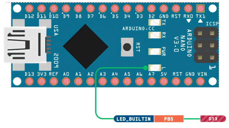
Pin D13 connects to the onboard LED, so it is the easiest pin for a first test without any wiring. The LED and its series resistor load the pin, which makes D13 less reliable as an input than the other pins.
Digital Pin Rules
- Call
pinMode()for a pin before you use it. - Add a resistor of 220 Ω to 330 Ω in series with every LED.
- Disconnect anything from D0 and D1 before you upload a sketch.
- Use a transistor, MOSFET or relay module for motors and other heavy loads.
Arduino Nano PWM Pins
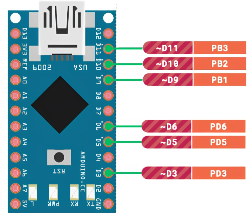
Six digital pins can produce PWM (pulse width modulation) signals, and the board marks them with a tilde (~). These pins are D3, D5, D6, D9, D10 and D11, and they are the same pins as on the UNO. The analogWrite() function accepts a value from 0 to 255 and sets the share of time that the pin stays HIGH. The Arduino PWM and analogWrite() tutorial covers duty cycle and frequency control in more detail.
| PWM pin | Timer | Default frequency |
|---|---|---|
| D3 | Timer2 | about 490 Hz |
| D5 | Timer0 | about 980 Hz |
| D6 | Timer0 | about 980 Hz |
| D9 | Timer1 | about 490 Hz |
| D10 | Timer1 | about 490 Hz |
| D11 | Timer2 | about 490 Hz |
PWM becomes active only after you call analogWrite() on a pin, so these pins work as ordinary digital pins otherwise. Pins that share a timer also share its settings. The tone() function uses Timer2, which disables PWM on D3 and D11 while a tone is playing, and the passive buzzer tutorial shows an example.
Arduino Nano Interrupt Pins
An interrupt lets the microcontroller pause its normal program and run a short function as soon as a pin changes state. The Nano handles interrupts in the same way as the UNO, with two dedicated external interrupt pins and pin change interrupts on most other pins.
External Interrupts on D2 and D3
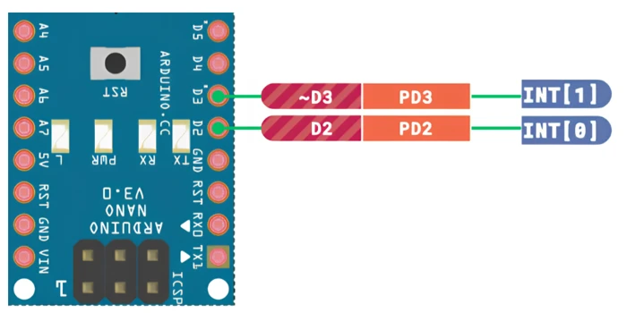
INT0 is on digital pin D2, and INT1 is on digital pin D3. You attach a handler with attachInterrupt(), and each pin has its own interrupt vector, which gives a direct response without extra checking in your code. The trigger can be RISING, FALLING, CHANGE or LOW. The Arduino external interrupts tutorial includes working examples and debounce handling.
Pin Change Interrupts
All digital pins and the analog pins A0 to A5 support pin change interrupts (PCINT). The pins are grouped by port, and each port shares one interrupt vector, so your handler has to read the pins to find out which one changed. The pins A6 and A7 are analog-only and do not support pin change interrupts.
| Feature | External interrupts (INT0, INT1) | Pin change interrupts (PCINT) |
|---|---|---|
| Available pins | D2 and D3 only | D0 to D13 and A0 to A5 |
| Separate handler per pin | Yes | No, one handler per port |
| Trigger modes | RISING, FALLING, CHANGE, LOW | CHANGE only |
| Ease of use | Simple | Requires manual pin checks |
Use D2 and D3 whenever they are free, and use pin change interrupts when you need more sources.
Arduino Nano Analog Pins
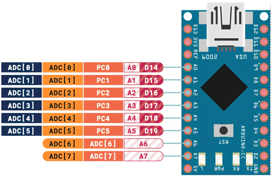
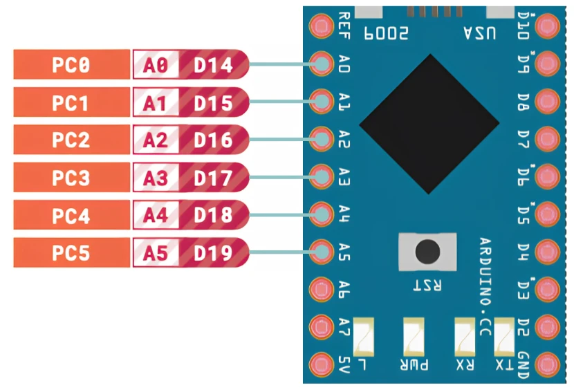
The Nano has eight analog input pins, labeled A0 to A7, while the UNO has six. All of them connect to the 10-bit ADC (analog-to-digital converter), so analogRead() returns a value from 0 to 1023.
How Analog Input Works
The ADC compares the input voltage with a reference voltage and returns a proportional number.
ADC value = (input voltage / reference voltage) × 1023The default reference is 5 V, so each step represents about 4.9 mV. This is enough for most sensors, such as temperature, light and potentiometer inputs. The Arduino ADC and analogRead() tutorial covers sampling, averaging and conversion to real units, and the GP2Y0A41SK0F distance sensor tutorial is an example of a sensor with an analog output.
A6 and A7 Are Analog-Only Pins
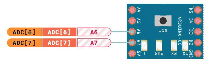
The pins A6 and A7 can be used only with analogRead(). They have no digital input or output function, so pinMode(), digitalWrite() and digitalRead() do not work on them. They also have no internal pull-up resistors. This is a common source of confusion for people who move from the UNO, because the UNO does not have these two pins at all.
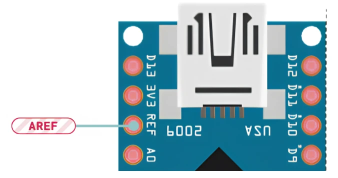
AREF Pin
The AREF pin lets you supply your own reference voltage to the ADC. If you apply 2.5 V to AREF and select the external reference in your code, the ADC range becomes 0 V to 2.5 V, and the same 1024 steps cover a smaller range, which gives finer resolution for small signals. The input voltage must stay below the reference voltage. Call analogReference(EXTERNAL) before you apply a voltage to AREF, because an internal reference is also connected to that pin, and an external source without this call can damage the chip.
Using A0 to A5 as Digital Pins
The pins A0 to A5 also work as ordinary digital pins. Use pinMode(A0, OUTPUT) or pinMode(A0, INPUT), and they behave like any other digital pin. This does not apply to A6 and A7.
Analog Pin Rules
- A6 and A7 are analog-only, and A0 to A5 can also be digital pins.
- Never apply more than 5 V to any analog pin.
- A floating analog input gives random readings, so connect it to a signal source or to a defined level.
- A lower AREF voltage improves resolution but reduces the usable input range.
Arduino Nano UART Pins
The Nano has one hardware UART, and it uses digital pin D0 as RX (receive) and digital pin D1 as TX (transmit). The same lines connect to the USB-to-serial chip, which carries the Serial Monitor traffic between the board and your computer.
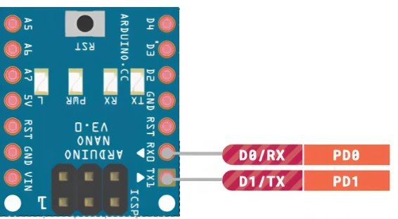
The original Nano uses an FT232RL chip for this task, and many clones use a CH340 chip instead. The CH340 works well, but Windows and macOS may need a driver that you install manually. Disconnect any wires from D0 and D1 before you upload a sketch, because the upload uses the same lines and a connected module can make the upload fail. The Arduino UART tutorial explains how to send and receive data.
SoftwareSerial for a Second Serial Port
The SoftwareSerial library creates an extra serial port on any two digital pins, which helps when a GPS or Bluetooth module needs a port while the hardware UART is busy with debug output. The library handles the timing in software, so it works reliably at 9600 baud and becomes less dependable at higher speeds.
Arduino Nano I2C Pins
I2C (Inter-Integrated Circuit) connects several devices to the same two wires, and each device has its own address. On the Nano, SDA (data) is on analog pin A4, and SCL (clock) is on analog pin A5. The Wire library handles the protocol, and the Arduino I2C tutorial shows how to scan the bus and troubleshoot it.
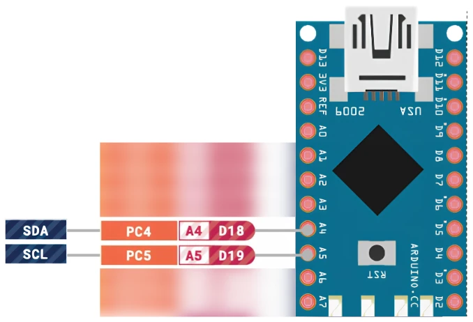
Common I2C devices for the Nano include the SSD1306 OLED display, the DS3231 real-time clock, the MPU-6050 motion sensor, the I2C LCD1602 display and the BME280 sensor. When the I2C bus is in use, A4 and A5 are no longer available as analog inputs, so plan the pins at the start of the project.
Arduino Nano SPI Pins
SPI (Serial Peripheral Interface) is the fastest of the three serial interfaces, and it uses four lines.
- MOSI (master out, slave in) is on pin D11.
- MISO (master in, slave out) is on pin D12.
- SCK (serial clock) is on pin D13.
- SS (slave select) is on pin D10.
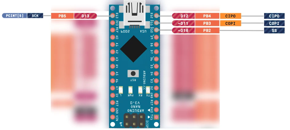
SPI suits devices that move a lot of data, such as the ST7735 TFT display, the SD card module, the W25Q flash memory chip and nRF24L01 radio modules. Each device needs its own chip-select pin. Pin D10 must stay an output while the Nano acts as an SPI master, even when you do not use it as the slave select line. If D10 is set as an input and goes LOW, the ATmega328P switches to SPI slave mode, and the sketch stops working correctly.
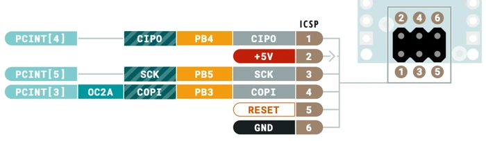
ICSP Header
The Nano has a 6-pin ICSP header that exposes MOSI, MISO, SCK, RESET, VCC and GND. An external programmer uses this header to write the bootloader to the chip. Most users never need it unless they replace the chip or erase the bootloader by accident.
Arduino Nano Timer and Input Capture Pins
A few pins connect directly to the hardware timers inside the ATmega328P, and they are the same as on the UNO.
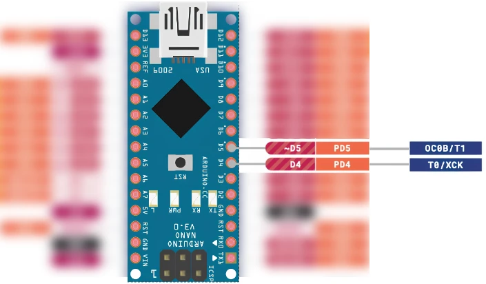
Timer Clock Input Pins T0 and T1
Pin D4 is the T0 input, and pin D5 is the T1 input. A timer that uses an external clock counts the pulses on its pin instead of the internal 16 MHz clock. This feature is used for frequency counters and for counting pulses from an encoder.
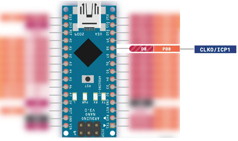
Input Capture Pin ICP1
Pin D8 is the input capture pin (ICP1) of Timer1. When an edge appears on the pin, the hardware copies the current Timer1 value into a register without any help from the CPU. This gives a precise time stamp for events, which is useful for measuring pulse widths and for reading an ultrasonic sensor such as the HC-SR04 more accurately than pulseIn() allows.
Arduino Nano vs Arduino UNO
Many people come to the Nano after they have worked with the UNO, so the table below lists the differences that matter when you plan a circuit. The microcontroller and the digital pin functions are the same, and the changes are mostly in the size, the analog pins and the USB hardware.
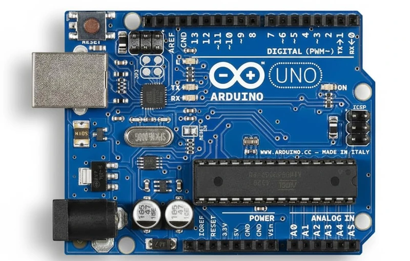
| Feature | Arduino UNO | Arduino Nano |
|---|---|---|
| Microcontroller | ATmega328P | ATmega328P |
| Size | 68.6 mm × 53.4 mm | 45 mm × 18 mm |
| Digital I/O pins | 14 | 14 |
| PWM pins | 6 | 6 |
| Analog input pins | 6 (A0 to A5) | 8 (A0 to A7) |
| A6 and A7 | Not available | Analog input only |
| USB connector | Type-B | Mini-B, Micro-USB or USB-C, depending on the board |
| DC power jack | Yes | No |
| Breadboard friendly | No | Yes |
| 3.3V pin source | Onboard 3.3 V regulator | FT232RL chip on the original board, 50 mA |
| ICSP header | Yes | Yes |
The core hardware is identical, and a sketch for one board usually runs on the other without changes. The Arduino UNO pinout guide lists the UNO side of this comparison in full.
Arduino Nano Pinout Table
The tables below list every pin of the Nano with its port on the ATmega328P, its PWM capability and its alternate functions.
Digital Pins
| Arduino pin | ATmega328P port | PWM | Alternate function | Description |
|---|---|---|---|---|
| D0 | PD0 | No | RX | UART receive |
| D1 | PD1 | No | TX | UART transmit |
| D2 | PD2 | No | INT0 | External interrupt 0 |
| D3 | PD3 | Yes | INT1 | External interrupt 1 |
| D4 | PD4 | No | T0 | Timer0 external clock |
| D5 | PD5 | Yes | T1 | Timer1 external clock |
| D6 | PD6 | Yes | None | PWM output |
| D7 | PD7 | No | None | General-purpose digital I/O |
| D8 | PB0 | No | ICP1 | Input capture unit |
| D9 | PB1 | Yes | None | PWM output |
| D10 | PB2 | Yes | SS | SPI slave select |
| D11 | PB3 | Yes | MOSI | SPI master out, slave in |
| D12 | PB4 | No | MISO | SPI master in, slave out |
| D13 | PB5 | No | SCK, LED | SPI clock and onboard LED |
Analog Pins
| Arduino pin | ATmega328P port | Digital I/O | Alternate function | Description |
|---|---|---|---|---|
| A0 | PC0 | Yes | None | Analog input or digital I/O |
| A1 | PC1 | Yes | None | Analog input or digital I/O |
| A2 | PC2 | Yes | None | Analog input or digital I/O |
| A3 | PC3 | Yes | None | Analog input or digital I/O |
| A4 | PC4 | Yes | SDA | I2C data, analog input or digital I/O |
| A5 | PC5 | Yes | SCL | I2C clock, analog input or digital I/O |
| A6 | ADC6 | No | None | Analog input only |
| A7 | ADC7 | No | None | Analog input only |
| AREF | None | No | AREF | External analog reference input |
Power Pins
| Pin | Description |
|---|---|
| VIN | External supply input, 7 V to 12 V recommended |
| 5V | Regulated 5 V rail |
| 3.3V | Regulated 3.3 V output, about 50 mA from the FT232RL on the original board |
| GND | Ground, two pins connected internally |
| RESET | Pull LOW to restart the microcontroller |
Conclusion
The Arduino Nano packs a lot into a very small package. Same ATmega328P chip as the UNO, same digital and communication pins, same PWM — but smaller, breadboard-friendly, and with two extra analog-only pins.
Once you understand the pinout — especially the A6/A7 limitation and the importance of keeping D10 as output for SPI — working with the Nano becomes very straightforward.
If you are moving over from the UNO, most of your knowledge carries over directly. The Nano is a natural next step, and it opens the door to building much more compact and portable projects.
Browse More Arduino Core Tutorials
Arduino ADC and analogRead() Explained: Complete Guide with Examples
Arduino I2C Tutorial: Wire Library, Master/Slave, Scanner & Troubleshooting
Arduino delayMicroseconds() Tutorial: Precise Timing, Pulses & Alternatives
Arduino PWM and analogWrite() Explained with Examples
Arduino External Interrupts: attachInterrupt(), ISR & Debounce

Subscribe
Login
0 Comments
Newest

