
Home ▸ Arduino ▸ Sensors Interfacing ▸
Updated On: May 21, 2026
DS18B20 Arduino Tutorial: Single & Multiple Sensors on One Wire — Serial & OLED Output
The DS18B20 is one of the most practical temperature sensors for Arduino. It uses the One-Wire protocol, where a single data pin handles all communication, all power (in parasite mode), and all sensor identification. Connect one DS18B20 or twenty to the same pin, add a 4.7 kΩ pull-up resistor, and every sensor responds to its unique 64-bit address. No I2C address juggling, no SPI chip selects, one wire.
In this tutorial you will learn how DS18B20 sensors work on the One-Wire bus, how to wire a single sensor with the required pull-up, and how to read temperature with the DallasTemperature library. We will then expand to multiple sensors on the same pin, scanning all device addresses, reading each one by index and by unique address, and displaying all readings on the Serial Monitor. Finally, you will build a standalone temperature display by connecting an SSD1306 OLED over I2C, leaving the One-Wire bus untouched. The waterproof version of the DS18B20 is covered in the wiring section, but the code is identical.
For a closer look at the SSD1306 OLED itself, the SSD1306 Arduino OLED Tutorial covers text, bitmaps, and animations in detail.
Working with other temperature sensors on Arduino? Check out these related guides:
- SHT21 Temperature & Humidity Sensor with Arduino
- AHT20 Temperature & Humidity Sensor with Arduino
- SHT3X (SHT30 / SHT31 / SHT35) with Arduino
- DHT11 & DHT22 Temperature & Humidity with Arduino
- BME280 Environmental Sensor with Arduino
- BMP180 Pressure & Temperature Sensor with Arduino
Browse the full Arduino Sensor Interfacing tutorial collection for more.
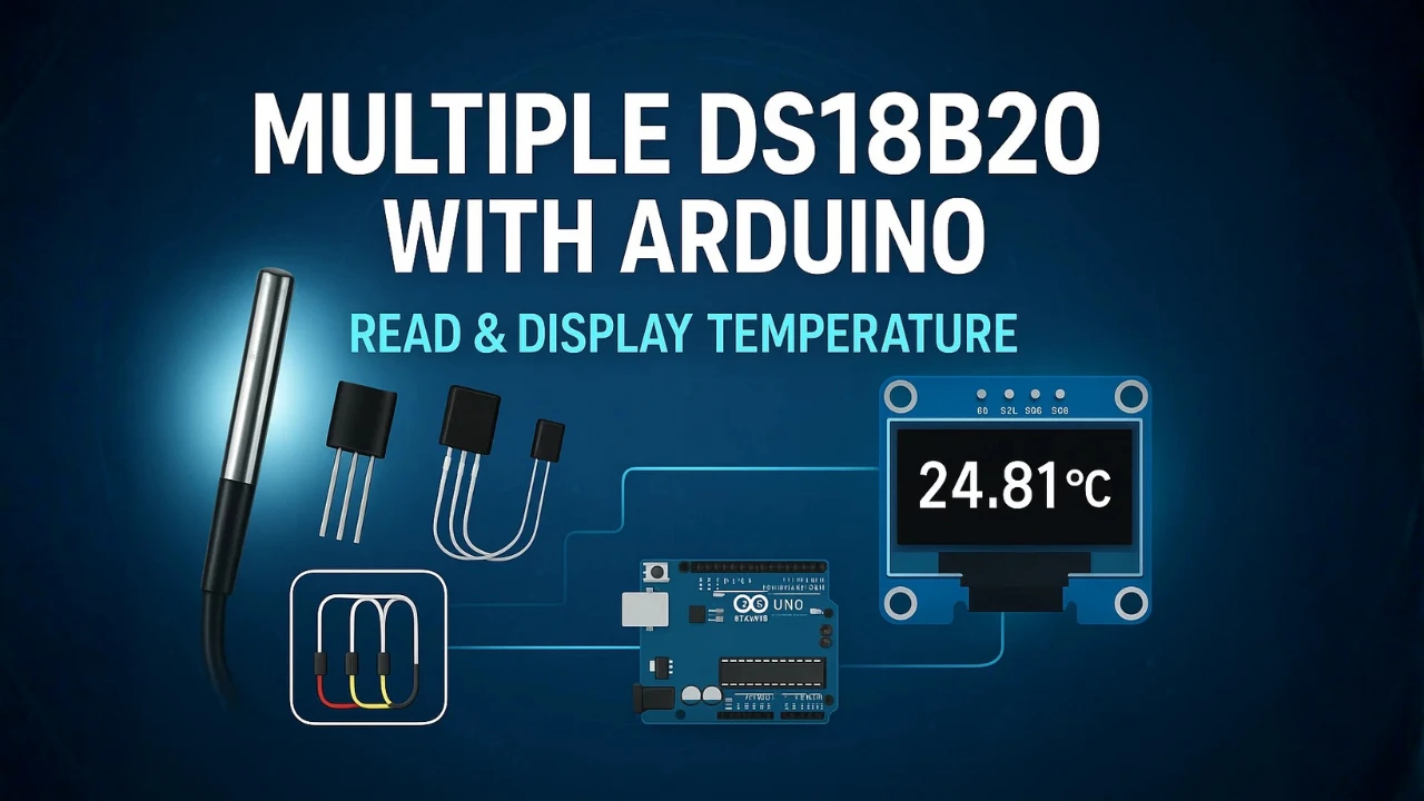
Table Of Contents
- DS18B20 Overview & How It Works
- DS18B20 Pinout & Wiring to Arduino
- Install OneWire & DallasTemperature Libraries
- Single DS18B20 — Serial Monitor Output
- Single DS18B20 on SSD1306 OLED Display
- Multiple DS18B20 Sensors on One Data Pin
- Troubleshooting DS18B20 with Arduino
- Arduino DS18B20 — Frequently Asked Questions
DS18B20 Overview & How It Works
What Is the DS18B20?
The DS18B20 is a digital temperature sensor used in many Arduino and IoT projects. It provides accurate temperature readings without the need for complex circuits. The sensor comes in a small TO-92 package, and it can also be found in a waterproof version for outdoor use. Because it uses digital communication, the readings stay stable even over long wires. This makes the DS18B20 a reliable choice for hobby and professional projects.
DS18B20 Key Features & Specifications
The DS18B20 is a versatile and reliable temperature sensor, ideal for both hobbyist and industrial applications. Its digital output, flexible wiring options, and accurate measurements make it a popular choice for projects that require precise temperature monitoring.
Key features of the DS18B20:
- Easy to expand and integrate into systems like weather stations, data loggers, and industrial monitors
- Measures temperatures from –55°C to +125°C with good accuracy
- Provides digital output, reducing noise and interference
- Supports 9 to 12-bit resolution for adjustable precision
- One-Wire interface allows multiple sensors on a single data line
- Can operate with standard 3-wire connection or parasite power mode
How the One-Wire Protocol Works
Most digital sensors use I2C (two wires: SDA and SCL) or SPI (four wires: MOSI, MISO, SCK, CS). The DS18B20 uses neither. It uses 1-Wire — a protocol developed by Dallas Semiconductor where a single data line carries power, timing, and bidirectional data between the master (Arduino) and every sensor on the bus.
Here is what happens on that single wire every time Arduino requests a temperature reading:
1. Reset pulse — Arduino pulls the data line LOW for at least 480 µs, then releases it. Every DS18B20 on the bus detects this as a reset and prepares to respond.
2. Presence pulse — Each sensor confirms it is alive by pulling the line LOW for 60–240 µs. Arduino reads this as “at least one sensor present.”
3. ROM command — Arduino sends either 0xCC (Skip ROM — address all sensors at once) or 0x55 (Match ROM — address one specific sensor by its 64-bit serial number).
4. Function command — Arduino sends 0x44 (Convert T — start a temperature conversion) or 0xBE (Read Scratchpad — read the result).
5. Data transfer — The DS18B20 holds the conversion result in its scratchpad memory. Arduino reads 9 bytes: 2 bytes of raw temperature, 6 bytes of configuration and alarm registers, and 1 CRC byte for error detection.
6. Temperature conversion — The two raw bytes are combined and divided by 16 to get °C. At 12-bit resolution (default), the precision is 0.0625°C per step.
The DallasTemperature library wraps all of this into sensors.requestTemperatures() and sensors.getTempCByIndex() — but understanding the underlying sequence helps when debugging missing sensors, parasite power issues, or multi-sensor address conflicts.
The key property that makes 1-Wire powerful: every DS18B20 is programmed at the factory with a unique 64-bit address (called a ROM code). No two sensors in the world share the same code. This means you can chain 10 sensors on a single wire and address each one individually — no I2C address conflicts, no SPI chip selects, no extra pins.
DS18B20 vs DHT22 vs SHT21: When to Use Each
All three sensors read temperature. The DHT22 and SHT21 also read humidity. If you only need temperature, the DS18B20 is the most capable option by a significant margin. If you need both temperature and humidity, the SHT21 is the cleaner choice.
| DS18B20 | DHT22 | SHT21 | |
|---|---|---|---|
| Measures | Temperature only | Temperature + Humidity | Temperature + Humidity |
| Temperature accuracy | ±0.5°C | ±0.5°C | ±0.3°C |
| Humidity accuracy | — | ±2–5% RH | ±2% RH |
| Interface | 1-Wire (single data pin) | Single-wire (proprietary) | I2C (standard) |
| Multiple sensors | Yes — up to ~100 on one pin | No — one per pin | No — one per I2C address |
| Waterproof version | Yes — stainless steel probe | No | No |
| Min sampling interval | 750 ms (12-bit conversion) | 2 seconds | No restriction |
| Supply voltage | 3.0V – 5.5V (or parasite) | 3.3V – 5V | 2.1V – 3.6V |
| Library | DallasTemperature + OneWire | Adafruit DHT | SHT2x (Rob Tillaart) |
| Fixed address | Unique 64-bit ROM code | — | 0x40 |
Use the DS18B20 when:
- You need temperature in a wet, outdoor, or harsh environment (waterproof probe version)
- You need to read multiple temperature points simultaneously on a single wire (tank monitoring, multi-zone HVAC, long cable runs)
- You need temperature at the end of a long cable — 1-Wire is reliable over 100+ metres with a good pull-up, whereas I2C is limited to a few metres
Use the DHT22 when:
- You need both temperature and humidity with no existing I2C bus
- You are building a quick prototype and have a spare digital pin
Use the SHT21 when:
- You need both temperature and humidity at higher accuracy
- You already have an I2C bus running (LCD, OLED, RTC) and want to add sensing with no extra pins
The DS18B20 and SHT21 are not competitors — they measure different things. A common combination is both on the same Arduino: DS18B20 on a digital pin for outdoor temperature, SHT21 on the I2C bus for indoor temperature and humidity.
Standard vs Waterproof DS18B20 Module
The DS18B20 chip itself comes in a TO-92 plastic package — the same small three-legged black transistor shape used for countless other components. Most breakout boards mount this chip on a small PCB with decoupling capacitors and a pull-up resistor already installed.
The waterproof version packages the same DS18B20 chip inside a stainless steel probe sealed with epoxy resin. The probe connects to a cable (typically 1 metre, though 3-metre and longer versions are available) with three wires: red (VDD), black (GND), and yellow or white (DQ data).
The code is identical for both versions. The DallasTemperature library cannot tell them apart — it communicates with the DS18B20 chip via 1-Wire regardless of the enclosure. You wire both versions the same way, with the same 4.7 kΩ pull-up resistor on the DQ line.
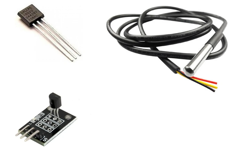
| Standard Breakout Module | Waterproof Probe | |
|---|---|---|
| Enclosure | PCB with exposed chip | Stainless steel sealed probe |
| Cable | Direct pin headers | Pre-attached 1 m cable |
| Weather resistance | None — indoor only | IP67 rated — submersible |
| Pull-up resistor | Usually included on PCB | Must add externally on DQ wire |
| Typical use | Breadboard prototyping, indoor sensing | Liquid temperature, outdoor, soil |
| Code difference | None | None |
One important difference: most breakout modules have the 4.7 kΩ pull-up resistor built onto the PCB. The waterproof probe version is just bare wires — you must add the pull-up resistor yourself between DQ (yellow/white) and VDD (red). Without it, the 1-Wire bus will not work and the sensor will return -127°C or simply not respond.
DS18B20 Pinout & Wiring to Arduino
The DS18B20 temperature sensor uses a simple 3-pin interface, which makes it extremely easy to connect with an Arduino. It communicates using the One-Wire protocol, meaning only one data pin is needed for communication. The other two pins are for power and ground.
DS18B20 3-Pin Pinout — VDD, DQ, GND
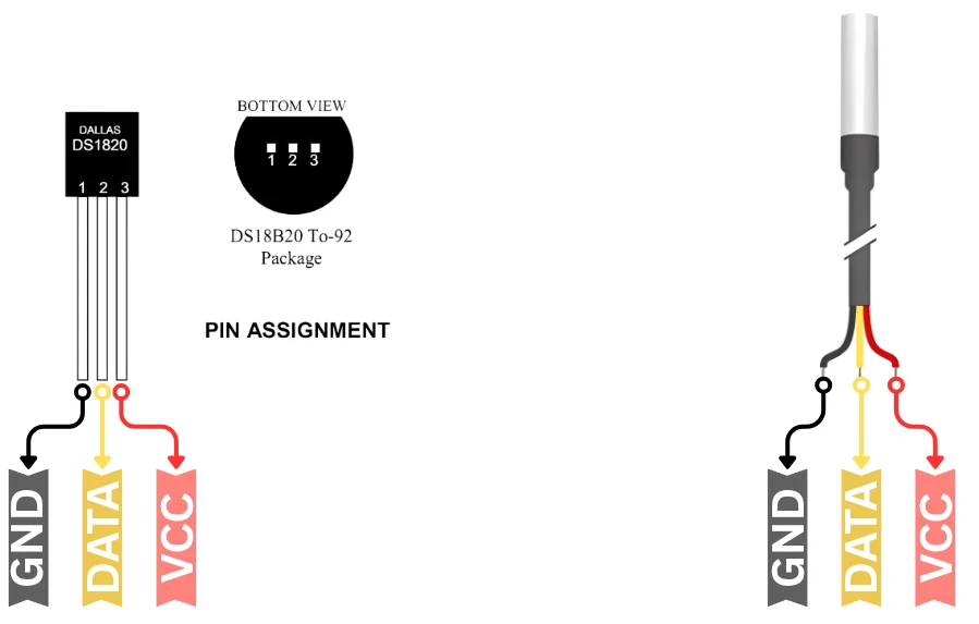
Here’s the pin description of the DS18B20 sensor:
| Pin Name | Function | Description |
|---|---|---|
| VDD | Power Supply | Connects to 3.3V or 5V from the Arduino (depending on wiring mode). |
| DQ | Data Line | One-Wire data pin used for communication. Requires a 4.7kΩ pull-up resistor to VCC. |
| GND | Ground | Connects to the Arduino ground. |
The DATA pin is the heart of the DS18B20. It carries all communication between the sensor and the Arduino. This pin works on the One-Wire protocol, so it handles sending and receiving data through a single line.
To make the DATA pin work correctly, you must place a 4.7kΩ pull-up resistor between the DATA pin and the VCC pin. This resistor keeps the data line stable and prevents false signals. Without this pull-up resistor, the Arduino may fail to detect the sensor or read wrong temperatures. The same rule applies whether you use one sensor or many sensors on the same line.
Wiring Diagram — Single DS18B20 to Arduino Uno
The DS18B20 connects to Arduino using only three wires. The image below shows how to connect the sensor to Arduino UNO.
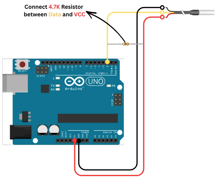
The data pin must have a 4.7kΩ pull-up resistor for stable communication. Below is the wiring table for a single DS18B20 sensor. This single resistor ensures proper communication. If you skip this step, the sensor may not respond or may show random readings.
| DS18B20 Pin | Arduino Pin | Description |
|---|---|---|
| VDD | 5V or 3.3V | Powers the sensor depending on module type. |
| DQ (Data) | Digital Pin 2 | Used for One-Wire data. Connect a 4.7kΩ resistor between DQ and VCC. |
| GND | GND | Common ground connection. |
Install OneWire & DallasTemperature Libraries
To read temperature from the DS18B20 sensor, you need two Arduino libraries:
- OneWire
- DallasTemperature
These libraries make the One-Wire communication easy. They also provide simple functions to get temperature directly from the sensor. Therfore you do not need to handle any low-level timing or protocol code.
Follow these steps to install them:
- Open the Arduino IDE.
- Go to Sketch → Include Library → Manage Libraries…
- In the search bar, type “OneWire” and install it.
- Then search “DallasTemperature” and install it as well.
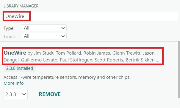
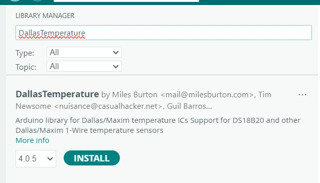
After installing both libraries, your Arduino is ready to read temperature from a DS18B20.
Single DS18B20 — Serial Monitor Output
Below is the code to read the temperature from one DS18B20 sensor using the One-Wire protocol.
#include <OneWire.h>
#include <DallasTemperature.h>

#define ONE_WIRE_BUS 2

OneWire oneWire(ONE_WIRE_BUS);
DallasTemperature sensors(&oneWire);

void setup() {
  Serial.begin(9600);
  sensors.begin();
}

void loop() {
  sensors.requestTemperatures();
  float tempC = sensors.getTempCByIndex(0);
  Serial.print("Temperature: ");
  Serial.print(tempC);
  Serial.println(" °C");
  delay(1000);
}Code Explained — Step by Step
1. Including Libraries
#include <OneWire.h>
#include <DallasTemperature.h>We include the OneWire library to handle One-Wire communication. And the DallasTemperature library to read temperature easily from the DS18B20 sensor.
2. Defining the Data Pin
#define ONE_WIRE_BUS 2The DS18B20 data pin is connected to Arduino digital pin 2. This macro helps us use the pin easily throughout the code.
3. Creating OneWire and DallasTemperature Objects
OneWire oneWire(ONE_WIRE_BUS);
DallasTemperature sensors(&oneWire);The first line creates a OneWire object on pin 2. The second line passes this OneWire object to the DallasTemperature library so it can talk to the sensor.
4. Setup Function
void setup() {
Serial.begin(9600);
sensors.begin();
}We start the Serial Monitor at 9600 baud rate. We also initialize the DS18B20 sensor using sensors.begin().
5. Loop Function
void loop() {
sensors.requestTemperatures();
float tempC = sensors.getTempCByIndex(0);We ask the sensor to take a new temperature reading. Then we read the temperature in Celsius from the first sensor on the bus.
6. Printing the Reading
Serial.print("Temperature: ");
Serial.print(tempC);
Serial.println(" °C");We print the temperature value on the Serial Monitor.
7. Delay Between Readings
delay(1000);
}Output — Temperature at 9600 Baud
After uploading the code, open the Arduino Serial Monitor. Set the baud rate to 9600. You will see the temperature value update automatically.
The image below shows the Temperature readings printed on the serial monitor of Arduino IDE.
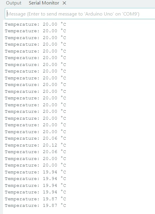
The DS18B20 provides a stable reading, so the temperature should not fluctuate rapidly. If you see errors or “-127°C”, it usually means there is a wiring issue.
Single DS18B20 on SSD1306 OLED Display
You can also show the temperature from the DS18B20 sensor on a 0.96″ SSD1306 OLED display. This I2C display uses only two wires, which makes it easy to connect and perfect for real-time temperature monitoring. In this section, we will use the Adafruit SSD1306 library to print the temperature clearly on the screen.
If you want to get more information about how to interafce the 0.96″ Oled display with Arduino, check out this guide: Interface 0.96″ SSD1306 Oled with Arduino.
Wiring Diagram: DS18B20 + SSD1306 to Arduino Uno
The 0.96″ SSD1306 OLED uses the I2C interface, which means it only needs two data wires along with power and ground. The wiring is simple and works with most Arduino boards, including the Arduino UNO.

Make sure the display is powered correctly. Most SSD1306 OLED modules work with both 3.3V and 5V, but some versions are 3.3V only. Always check your module printing before powering it.
Below is the wiring table for the SSD1306 I2C OLED display:
| OLED Pin | Arduino Pin | Description |
|---|---|---|
| VCC | 3.3V | Powers the OLED display (depends on module). |
| GND | GND | Common ground connection. |
| SDA | A4 | I2C data line for communication. |
| SCL | A5 | I2C clock line for communication. |
Install Adafruit SSD1306 and GFX Libraries
To begin, open your Arduino IDE and follow these steps:
- Go to the Sketch menu → Include Library → Manage Libraries…
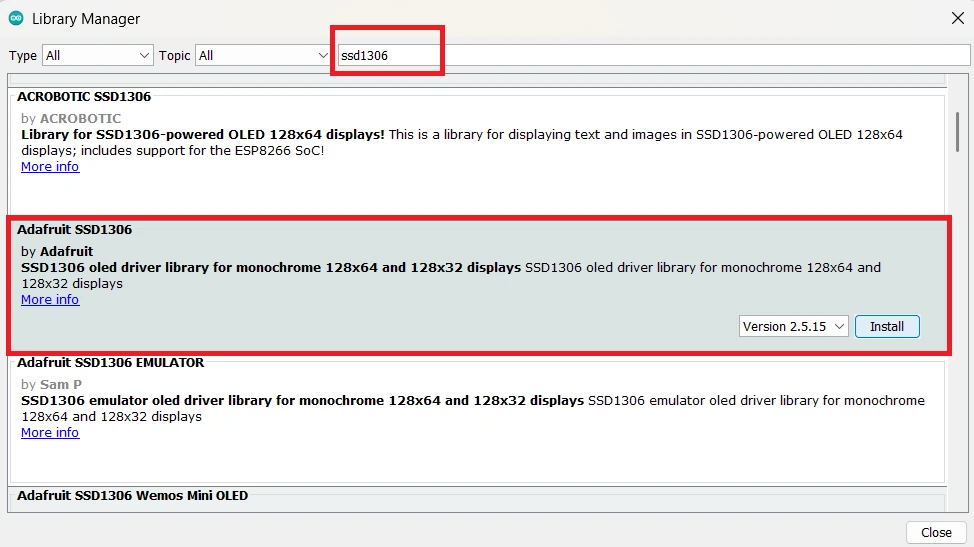
- In the Library Manager, type “SSD1306” in the search bar.
- Find Adafruit SSD1306 by Adafruit and click Install.
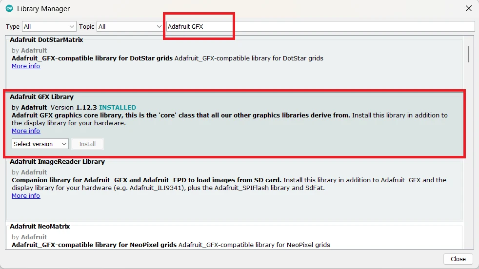
- Next, search for “Adafruit GFX” and install Adafruit GFX Library as well.
Complete Code — DS18B20 + SSD1306 OLED
Here is the OLED version of the code:
#include <OneWire.h>
#include <DallasTemperature.h>
#include <Adafruit_GFX.h>
#include <Adafruit_SSD1306.h>
#define ONE_WIRE_BUS 2
#define SCREEN_WIDTH 128
#define SCREEN_HEIGHT 64
Adafruit_SSD1306 display(SCREEN_WIDTH, SCREEN_HEIGHT, &Wire, -1);
OneWire oneWire(ONE_WIRE_BUS);
DallasTemperature sensors(&oneWire);
void setup() {
Serial.begin(9600);
sensors.begin();
display.begin(SSD1306_SWITCHCAPVCC, 0x3C);
display.clearDisplay();
}
void loop() {
sensors.requestTemperatures();
float tempC = sensors.getTempCByIndex(0);
display.clearDisplay();
display.setTextSize(2);
display.setTextColor(WHITE);
display.setCursor(0, 20);
display.print("Temp: ");
display.print(tempC);
display.print(" C");
display.display();
delay(1000);
}Code Explanation:
This example reads temperature from one DS18B20 sensor and shows it on a 0.96″ SSD1306 OLED display using I2C.
1. Including Required Libraries
#include <OneWire.h>
#include <DallasTemperature.h>
#include <Adafruit_GFX.h>
#include <Adafruit_SSD1306.h>OneWire.his used for One-Wire communication with the DS18B20.DallasTemperature.hmakes temperature reading easy.Adafruit_GFX.hprovides basic graphics functions for the OLED.Adafruit_SSD1306.his the main library for the SSD1306 OLED display.
2. Defining Pins and Screen Size
#define ONE_WIRE_BUS 2
#define SCREEN_WIDTH 128
#define SCREEN_HEIGHT 64- The DS18B20 data pin is connected to D2.
- The OLED has a resolution of 128×64 pixels.
3. Creating Display and Sensor Objects
Adafruit_SSD1306 display(SCREEN_WIDTH, SCREEN_HEIGHT, &Wire, -1);
OneWire oneWire(ONE_WIRE_BUS);
DallasTemperature sensors(&oneWire);- The first line creates the OLED display object using I2C.
- The OneWire object is created on pin 2.
- The DallasTemperature object uses this OneWire object to talk to the sensor.
4. Setup Function
void setup() {
Serial.begin(9600);
sensors.begin();
display.begin(SSD1306_SWITCHCAPVCC, 0x3C);
display.clearDisplay();
}- Serial Monitor starts at 9600 baud.
- The DS18B20 sensor is initialized.
- The OLED display starts with I2C address 0x3C.
- The screen is cleared before writing anything.
5. Reading Temperature
sensors.requestTemperatures();
float tempC = sensors.getTempCByIndex(0);- We request a fresh temperature reading.
- Then we read the Celsius value from the first sensor.
6. Displaying Temperature on OLED
display.clearDisplay();
display.setTextSize(2);
display.setTextColor(WHITE);
display.setCursor(0, 20);
display.print("Temp: ");
display.print(tempC);
display.print(" C");
display.display();- Clear the screen before updating.
- Set text size to 2 for easy visibility.
- Set text color to white.
- Move the cursor to start writing text.
- Print temperature on the OLED.
display.display()updates the screen.
7. Delay Between Updates
delay(1000);- Wait 1 second before taking the next reading.
Output — Temperature on OLED Screen
Once the code is uploaded successfully, the oled should print the Temperature value as shown in the image below.
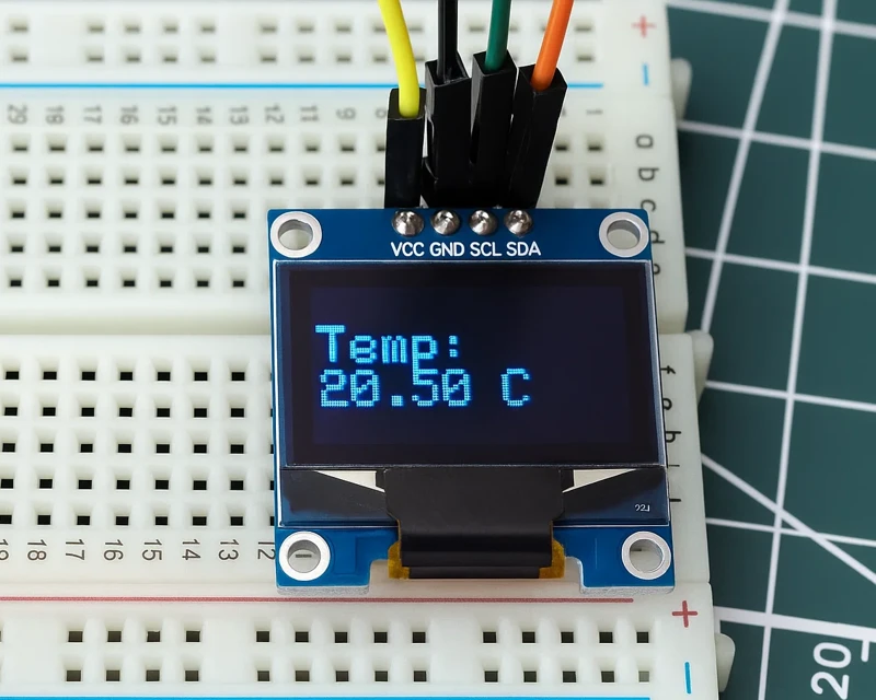
This value will update every second.
Multiple DS18B20 Sensors on One Data Pin
Connecting multiple DS18B20 temperature sensors with Arduino is easy because all sensors share the same data line. Each sensor has a unique 64-bit address. This allows the Arduino to read temperatures from all connected sensors one by one. In this part, we will see the connection, Arduino code, Serial Monitor output, and how to show multiple readings on a 0.96″ SSD1306 I2C OLED display.
How Multiple Sensors Share the Same Wire
All DS18B20 sensors use the One-Wire protocol. This lets many sensors work on the same wire without conflict. Each sensor has a unique ROM address. The Arduino reads each address and then fetches the temperature for that specific sensor.
This makes wiring simple, reduces pin usage, and works well for projects like room monitoring or multi-point temperature tracking.
Wiring Diagram — Multiple DS18B20 to Arduino
When using multiple DS18B20 sensors, all sensors connect in parallel:
| DS18B20 Pin | Arduino Pin | Description |
|---|---|---|
| VDD | 5V or 3.3V | Power for all sensors (connected together). |
| DQ (Data) | Digital Pin 2 | Shared by all sensors. Use a 4.7kΩ pull-up resistor between DQ and VCC. |
| GND | GND | Ground for all sensors (connected together). |
The image below shows how Three DS18B20 sensors are connected in parallel on the same line and are powered by the same supply.
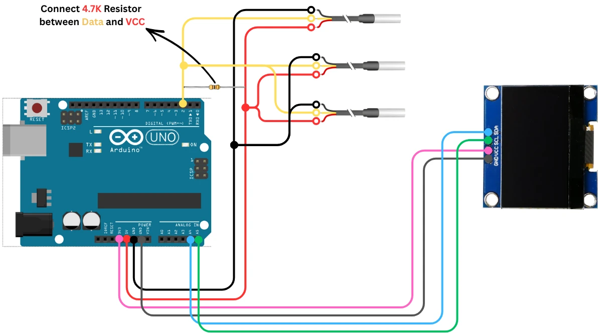
Just connect the VCC pins from All the sensors together, GND pins together and data pins together. Then connect the combined pins to the Arduino.
This wiring supports 2, 5, or even 10 sensors on the same data line.
Arduino Code to Read Multiple DS18B20 Sensors
Here is the code to read temperatures from multiple DS18B20 sensors and display all readings on the OLED screen:
#include <OneWire.h>
#include <DallasTemperature.h>
#include <Adafruit_GFX.h>
#include <Adafruit_SSD1306.h>
#define ONE_WIRE_BUS 2
#define SCREEN_WIDTH 128
#define SCREEN_HEIGHT 64
Adafruit_SSD1306 display(SCREEN_WIDTH, SCREEN_HEIGHT, &Wire, -1);
OneWire oneWire(ONE_WIRE_BUS);
DallasTemperature sensors(&oneWire);
void setup() {
Serial.begin(9600);
sensors.begin();
display.begin(SSD1306_SWITCHCAPVCC, 0x3C);
display.clearDisplay();
}
void loop() {
sensors.requestTemperatures();
int deviceCount = sensors.getDeviceCount();
display.clearDisplay();
display.setTextSize(1);
display.setTextColor(WHITE);
display.setCursor(0, 0);
for (int i = 0; i < deviceCount; i++) {
float tempC = sensors.getTempCByIndex(i);
// Print on serial
Serial.print("Sensor ");
Serial.print(i);
Serial.print(": ");
Serial.print(tempC);
Serial.println(" °C");
// Print on OLED
display.print("S");
display.print(i);
display.print(": ");
display.print(tempC);
display.println(" C");
}
display.display();
Serial.println("------------------");
  delay(1000);
}Code Explanation
1. Including All Required Libraries
#include <OneWire.h>
#include <DallasTemperature.h>
#include <Adafruit_GFX.h>
#include <Adafruit_SSD1306.h>OneWire.hhandles the One-Wire communication.DallasTemperature.hmakes reading multiple DS18B20 sensors easy.Adafruit_GFX.hprovides basic graphics functions.Adafruit_SSD1306.hcontrols the OLED display.
2. Defining Pin and OLED Screen Size
#define ONE_WIRE_BUS 2
#define SCREEN_WIDTH 128
#define SCREEN_HEIGHT 64- The DS18B20 sensors are connected to Arduino Pin 2.
- The OLED display resolution is 128 x 64 pixels.
3. Creating Sensor and Display Objects
Adafruit_SSD1306 display(SCREEN_WIDTH, SCREEN_HEIGHT, &Wire, -1);
OneWire oneWire(ONE_WIRE_BUS);
DallasTemperature sensors(&oneWire);- Creates the OLED display object using the I2C interface.
- Creates a One-Wire object for communication on pin 2.
- The DallasTemperature object uses the One-Wire bus to detect and read multiple sensors.
4. Setup Function
void setup() {
  Serial.begin(9600);
  sensors.begin();

  display.begin(SSD1306_SWITCHCAPVCC, 0x3C);
  display.clearDisplay();
}- Starts the Serial Monitor at 9600 baud rate.
- Detects and initializes all DS18B20 sensors connected to the bus.
- Initializes the OLED display at I2C address 0x3C.
- Clears the display before writing text.
5. Requesting Temperatures and Counting Sensors
sensors.requestTemperatures();
int deviceCount = sensors.getDeviceCount();- Requests fresh readings from all attached sensors.
- Gets the total number of DS18B20 sensors detected.
6. Preparing the OLED Display
display.clearDisplay();
display.setTextSize(1);
display.setTextColor(WHITE);
display.setCursor(0, 0);- Clears the screen.
- Sets the text size to 1 so all readings fit.
- Sets the text color to white.
- Positions the cursor at the top-left corner.
7. Looping Through All Sensors
for (int i = 0; i < deviceCount; i++) {
float tempC = sensors.getTempCByIndex(i);- Loops through each DS18B20 sensor.
- Reads the temperature of sensor number i.
8. Printing Values on Serial Monitor
Serial.print("Sensor ");
Serial.print(i);
Serial.print(": ");
Serial.print(tempC);
Serial.println(" °C");- Prints the sensor number and its temperature.
- Helps in debugging and monitoring values in real time.
9. Printing Values on the OLED Display
display.print("S");
display.print(i);
display.print(": ");
display.print(tempC);
display.println(" C");- Shows each sensor’s reading on the OLED.
- Each line displays something like:
S0: 25.4 C
10. Updating the OLED Screen
display.display();- Renders the new content on the screen.
11. Delay and Separator
Serial.println("------------------");
delay(1000);- Prints a separator line for better readability.
- Waits 1 second before taking the next reading.
Output: Multiple DS18B20 on SSD1306 OLED
Once the code is uploaded successfully, the oled should print the Temperature values from all the sensors as shown in the image below.

I have placed three sensors inside three cups, each containing water at a different temperature. One cup has hot water, another has ice-cold water, and the third contains water at normal room temperature. As you can see, the OLED display is showing the temperature readings from all three sensors.
The display updates every second, which makes it perfect for real-time monitoring.
Troubleshooting DS18B20 with Arduino
Even though the DS18B20 is easy to use, you may face a few common problems while testing your project. Most issues are related to wiring, missing resistors, or loose connections. In this section, you will learn how to identify and fix the most common DS18B20 errors when working with Arduino.
Common Wiring Issues
Most problems come from incorrect wiring. The DS18B20 has three pins, and mixing them up will stop the sensor from working. Make sure the middle pin is the DATA pin, the right pin goes to VCC, and the left pin goes to GND.
Another common issue is a missing or incorrect pull-up resistor. The DATA line must have a 4.7kΩ resistor connected between DATA and VCC. If the resistor is not connected, the sensor may show random values or fail to respond.
Also check for loose jumper wires or poor breadboard contact. A small loose connection can break communication and cause unstable readings.
Sensor Not Detected
If your Serial Monitor shows -127°C, it means the Arduino cannot detect the sensor.
This usually happens due to one of these reasons:
- Wrong wiring
- DATA pin not connected properly
- Missing 4.7kΩ pull-up resistor
- Using a very long cable without proper grounding
- Bad sensor (rare)
Double-check your connections carefully. If you are using multiple sensors, make sure all sensors share the same GND.
If the sensor is still not detected, try switching to another digital pin or using shorter wires during testing.
Wrong Temperature Reading
If the sensor is detected but the values are incorrect, the issue is usually related to power or long wire length.
Here are some common fixes:
- Ensure the sensor is powered with a stable 5V or 3.3V
- If using long cables, avoid thin wires that cause voltage drop
- Avoid placing the sensor near heat sources or power components
- For waterproof DS18B20 probes, make sure the metal tip is not touching electrical parts or metal surfaces
Sometimes the sensor takes a moment to stabilize after powering up. Give it a few seconds before taking final readings.
If you see values jumping suddenly or dropping to unrealistic levels, check the pull-up resistor. A weak or missing resistor causes unstable data.
Arduino DS18B20 — Frequently Asked Questions
Conclusion
The DS18B20 is one of the most flexible temperature sensors in the Arduino ecosystem. A single 4.7 kΩ pull-up resistor, one GPIO pin, and the DallasTemperature library — and you can chain as many sensors as your bus can handle, each identified by its unique 64-bit factory-programmed address. No I2C multiplexers, no address conflicts, no extra wiring per sensor.
In this tutorial you covered the complete picture: how the One-Wire protocol assigns unique addresses so multiple sensors share a single wire, how parasite power eliminates the VDD connection for battery-tight builds, how to wire the standard and waterproof DS18B20 variants with the required pull-up, and how to write code that reads a single sensor, scans all sensors on the bus, and reads each by index or by its specific address. You then added an SSD1306 OLED over I2C — a separate bus that does not interact with the One-Wire data line — for a standalone multi-sensor temperature display.
The -127°C error always means a wiring problem. The 85°C error always means the sensor powered on but was read before a conversion completed. Both are detectable in code — the getTempCByIndex() function returns these sentinel values intentionally. Add a check in your loop() and discard or retry the reading rather than displaying it.
From here you can log timestamped temperature arrays to an SD card using a DS3231 RTC for precise interval logging, or combine the DS18B20 with an AHT20 or SHT3X on the same Arduino to get both temperature and humidity from two independent sensor lines. Download the full project above and explore the Arduino Sensor Interfacing collection for more.
Download DS18B20 Arduino Project Files
Complete Arduino project with three sketches: single DS18B20 Serial Monitor output (getTempCByIndex(0) with -127°C error check), single DS18B20 + SSD1306 OLED display, and multiple DS18B20 sensors — address scan, read by index, and read by unique 64-bit address. Requires OneWire, DallasTemperature, Adafruit SSD1306, and GFX libraries. Compatible with Arduino Uno, Nano, and Mega. Free to download — support the work if it helped you.
Browse More Arduino Sensors Tutorials
SHT21 Arduino Tutorial: I2C Wiring, SHT2x Library, Serial & LCD Output
AHT20 Arduino Tutorial: I2C Wiring, Adafruit AHTX0 & OLED Display

SHT30 / SHT31 / SHT35 Arduino Tutorial: I2C Wiring, Code & LCD1602 Display
BMP180 Arduino Tutorial: I2C Wiring, Temperature, Pressure, Altitude & LCD1602
Arduino BME280 Tutorial: Wiring, Pinout, Code and LCD1602 Display Output

Subscribe
Login
0 Comments
Newest

