
Home ▸ Arduino ▸ Core Tutorials ▸
Updated On: June 27, 2026
Arduino PWM and analogWrite(): Complete Guide with Examples
analogWrite() does not output a true analog voltage. It uses PWM (Pulse Width Modulation) to rapidly switch a digital pin ON and OFF. The connected device responds to the average voltage, not the individual pulses. The result is smooth LED dimming, variable motor speed, and waveform generation using nothing but a digital pin.
In this guide, you will learn:
- How PWM works — duty cycle, frequency, and average voltage
- Which pins support PWM on each Arduino board
- How to use
analogWrite()for LED brightness and motor speed control - How to change PWM frequency and resolution using timer registers or libraries
- How to fix the most common PWM problems
This is part of the Arduino Core Tutorials series. If you’re new to Arduino I/O, start with the following:
How PWM Works
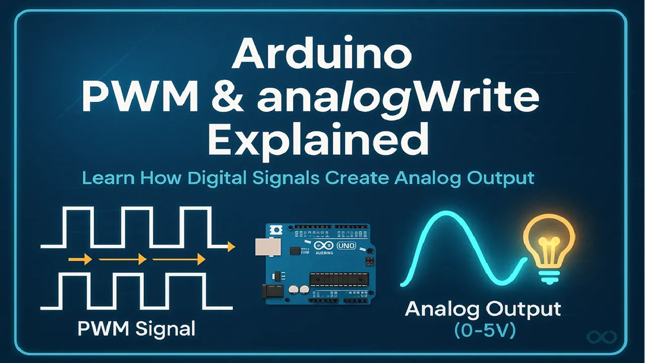
A digital pin can only be HIGH (5V) or LOW (0V). It cannot output 2.5V or 3.3V directly. PWM works around this by switching the pin ON and OFF very fast — thousands of times per second. The average voltage delivered to the device depends on the ratio of ON time to OFF time within each cycle.
Duty cycle is that ratio, expressed as a percentage:
- 0% duty cycle → pin always LOW → 0V average
- 50% duty cycle → pin ON half the time → 2.5V average
- 100% duty cycle → pin always HIGH → 5V average
Frequency is how many ON/OFF cycles happen per second, measured in Hz. On Arduino UNO and Nano, the default is 490 Hz on most pins and 980 Hz on pins 5 and 6. At these speeds, the switching is invisible to an LED and inaudible to a motor.
PWM Square Wave (Varying Duty Cycle)
Duty Cycle: 0%
Analog Voltage (0-5V)
Voltage: 0.00V
The formula for average output voltage is:
Average Voltage = (Duty Cycle / 100) × VREFAt 5V with a 75% duty cycle: 0.75 × 5V = 3.75V average.
PWM Pins by Board
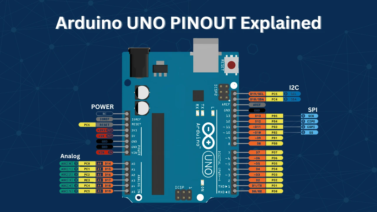
PWM is generated by hardware timers inside the microcontroller. Only pins connected to those timers can use analogWrite(). On most boards, PWM pins are marked with a ~ symbol.
| Board | PWM Pins |
|---|---|
| UNO / Nano / Pro Mini | 3, 5, 6, 9, 10, 11 |
| Mega 2560 | 2–13, 44–46 |
| Leonardo / Micro | 3, 5, 6, 9, 10, 11, 13 |
| Due | All digital pins (true DAC on A0, A1) |
| ESP32 | Almost all pins (via LEDC module) |
Calling analogWrite() on a non-PWM pin produces no output. If you are unsure, check the board's pinout for the ~ marking.
analogWrite() Function
analogWrite() sets the duty cycle of the PWM signal on a supported pin. You do not need to configure timers — the function handles everything internally.
Syntax
analogWrite(pin, value);pin— a PWM-capable pin numbervalue— duty cycle from0(always OFF) to255(always ON)
| Value | Duty Cycle | Average Voltage (5V board) |
|---|---|---|
| 0 | 0% | 0V |
| 64 | 25% | 1.25V |
| 128 | 50% | 2.5V |
| 192 | 75% | 3.75V |
| 255 | 100% | 5V |

You do not need to call pinMode(pin, OUTPUT) before analogWrite() — it configures the pin automatically. That said, calling it explicitly is good practice and makes your intent clear.
Default Frequency and Resolution
On AVR-based boards (UNO, Nano, Mega), the default PWM resolution is 8-bit — 256 steps from 0 to 255. The default frequencies are:
- 490 Hz — pins 3, 9, 10, 11 (Timer1 and Timer2)
- 980 Hz — pins 5 and 6 (Timer0)
On Arduino Due and ESP32, you can configure higher resolution (10–16 bit) and custom frequencies.
LED and Motor Control Examples
LED Brightness Control
Connect an LED through a 220 Ω resistor to pin 9. The example below fades the LED from off to full brightness and back in a continuous loop.
const int ledPin = 9;  // PWM pin connected to LED

void setup() {
  pinMode(ledPin, OUTPUT);
}

void loop() {
  for (int brightness = 0; brightness <= 255; brightness++) {
    analogWrite(ledPin, brightness);  // Fade in
    delay(10);
  }

  for (int brightness = 255; brightness >= 0; brightness--) {
    analogWrite(ledPin, brightness);  // Fade out
    delay(10);
  }
}Each step increases the duty cycle by roughly 0.4% (1/255). With a 10 ms delay per step, the full fade takes 2.55 seconds in each direction.

The oscilloscope confirms the duty cycle increasing and decreasing as the code runs. The voltmeter on pin 9 tracks the average voltage from 0V to 5V.
Motor Speed Control
Do not connect a DC motor directly to an Arduino pin — the motor draws more current than the pin can supply. Use a motor driver (L298N, L293D) or a logic-level MOSFET. Connect the motor driver's input to a PWM pin.
const int motorPin = 5;  // PWM output to motor driver input

void setup() {
  pinMode(motorPin, OUTPUT);
}

void loop() {
  analogWrite(motorPin, 128);  // ~50% duty cycle — half speed
  delay(2000);

  analogWrite(motorPin, 255);  // 100% duty cycle — full speed
  delay(2000);

  analogWrite(motorPin, 0);    // 0% duty cycle — stop
  delay(2000);
}The motor driver converts the PWM signal into proportional motor current. Higher duty cycle → more average voltage → higher speed.

Pin 5 runs at 980 Hz by default. For quieter motor operation, increase the frequency above 20 kHz (see the next section).
Changing PWM Frequency
The default PWM frequencies work for most projects. You may need to change them if:
- An LED flickers visibly (frequency too low — raise above 1 kHz)
- A motor whines audibly (raise above 20 kHz to move noise above hearing range)
- You are generating a specific signal frequency (audio, servo, etc.)
PWM frequency is set by the timer prescaler — a divider applied to the 16 MHz system clock before it reaches the timer. Lowering the prescaler raises the frequency.
Changing Frequency via Timer Registers
Pins 5 and 6 — Timer0:
// Timer0 — affects pins 5 and 6
// Default prescaler: 64 → 980 Hz
TCCR0B = (TCCR0B & 0b11111000) | 0x01;  // Prescaler 1 → ~62.5 kHz
TCCR0B = (TCCR0B & 0b11111000) | 0x02;  // Prescaler 8 → ~7.8 kHz
TCCR0B = (TCCR0B & 0b11111000) | 0x03;  // Prescaler 32 → ~1.96 kHz
Note:
Timer0 drives millis(), micros(), and delay(). Changing its prescaler will break time-keeping functions. Avoid this unless you have a specific reason and handle timing another way.
Pins 9 and 10 — Timer1 (safe to change):
// Timer1 — affects pins 9 and 10
// Default prescaler: 64 → 490 Hz
TCCR1B = (TCCR1B & 0b11111000) | 0x01;  // Prescaler 1 → ~31.4 kHz
TCCR1B = (TCCR1B & 0b11111000) | 0x02;  // Prescaler 8 → ~3.9 kHz
TCCR1B = (TCCR1B & 0b11111000) | 0x03; // Prescaler 64 → 490 Hz (default)Pins 3 and 11 — Timer2 (safe to change):
// Timer2 — affects pins 3 and 11
TCCR2B = (TCCR2B & 0b11111000) | 0x01;  // Prescaler 1 → ~31.4 kHz
TCCR2B = (TCCR2B & 0b11111000) | 0x02;  // Prescaler 8 → ~3.9 kHz
TCCR2B = (TCCR2B & 0b11111000) | 0x06; // Prescaler 256 → ~122 HzAfter changing the prescaler, continue using analogWrite() normally — it still sets the duty cycle correctly.
Custom Frequency with Timer1 Registers
For precise frequency control, configure Timer1 directly in Fast PWM mode with ICR1 as TOP:
void setup() {
  pinMode(9, OUTPUT);

  // Fast PWM, ICR1 as TOP, no prescaler
  TCCR1A = (1 << COM1A1) | (1 << WGM11);
  TCCR1B = (1 << WGM13) | (1 << WGM12) | (1 << CS10);

  // Frequency = 16,000,000 / (prescaler × ICR1)
  // 16,000,000 / (1 × 400) = 40,000 Hz → 40 kHz
  ICR1 = 400;

  // Duty cycle = OCR1A / ICR1 = 200 / 400 = 50%
  OCR1A = 200;
}The formula for frequency: F = 16,000,000 / (prescaler × ICR1). Adjust ICR1 for frequency and OCR1A for duty cycle.
PWM Libraries (Easier Alternative)
If manually tweaking timer registers feels too complex, there are Arduino libraries that simplify the process. They allow you to set custom frequency and resolution easily, without dealing with low-level timer code.
- TimerOne — Easy Timer1 control for pins 9 and 10
- PWM library — Per-pin frequency control on AVR boards
On ESP32, use the built-in LEDC API:
const int ledPin = 5;
const int channel = 0;
const int freq = 5000;      // 5 kHz
const int resolution = 8;   // 8-bit (0–255)

void setup() {
  ledcSetup(channel, freq, resolution);
  ledcAttachPin(ledPin, channel);
}

void loop() {
  for (int duty = 0; duty <= 255; duty++) {
    ledcWrite(channel, duty);
    delay(10);
  }
}ledcSetup() sets the frequency and resolution. ledcWrite() sets the duty cycle — the same role analogWrite() plays on AVR boards.
Arduino PWM Troubleshooting
analogWrite() Has No Effect
The pin does not support PWM. Only pins with a ~ symbol can use analogWrite(). Move the connection to a valid PWM pin.
If the pin is correct but still not responding, a library you are using (Servo, tone, a motor driver library) may have taken over that pin's timer. Check your includes and move to a pin on a different timer.
LED Flickers
The PWM frequency is too low — the switching is visible to the eye. Increase the frequency to above 1 kHz using the timer prescaler method above. Pins 5 and 6 at their default 980 Hz are usually flicker-free. Pins 3, 9, 10, 11 at 490 Hz may flicker in some conditions.
Motor Whines or Buzzes
490 Hz PWM falls within the audible range (20 Hz to 20 kHz). The motor's coils vibrate at the switching frequency, producing audible noise. Raise the frequency above 20 kHz to push the noise above hearing range. Use Timer1 or Timer2 for this — avoid changing Timer0.
millis() or delay() Stopped Working
You changed the Timer0 prescaler. Timer0 drives all Arduino time-keeping functions. Restoring TCCR0B to its default value fixes this:
TCCR0B = (TCCR0B & 0b11111000) | 0x03; // Restore Timer0 to default (prescaler 64)Servo Jitter After Adding analogWrite()
The Servo library uses Timer1 (pins 9 and 10 on UNO). If you call analogWrite() on pin 9 or 10 after including the Servo library, it will conflict. Use pins 3, 5, 6, or 11 for PWM when the Servo library is active.
Arduino PWM and analogWrite(): FAQs
Conclusion
PWM is one of the most practical tools in your Arduino toolkit. Once you understand that analogWrite() is really just controlling the ON/OFF ratio of a digital pin — and that the hardware timer handles the switching automatically — the behavior becomes completely predictable. You know exactly why a low duty cycle dims an LED, why a high frequency removes motor noise, and why changing Timer0 breaks delay().
From here, the natural next step depends on what you're building. If you need to read analog signals back into the Arduino, analogRead() and ADC covers the other direction of analog I/O. If you want to control the exact moment a PWM action happens — for example, syncing motor changes to a button press without delay-based blocking — external interrupts is the right follow-up. And if you're working with ESP32 instead of Uno, the LEDC-based PWM shown in the library section of this article gives you far more frequency and resolution flexibility than AVR timers allow.
Browse More Arduino Core Tutorials
Arduino Nano Pinout – Complete Guide with Diagram
Arduino digitalWrite() and digitalRead(): Complete Guide with Examples
Arduino UART Tutorial: Serial Communication, Send, Receive & LED Control
Arduino ADC and analogRead() Explained: Complete Guide with Examples
Arduino I2C Tutorial: Wire Library, Master/Slave, Scanner & Troubleshooting

Subscribe
Login
0 Comments
Newest

