
Home ▸ Arduino ▸ Displays & Interfaces ▸
Updated On: May 4, 2026
ST7735 Arduino TFT Tutorial: SPI Wiring, Graphics, Text & SD Card Image Display
The 1.8-inch ST7735 is one of the most popular TFT displays for Arduino projects — small, colorful, fast over SPI, and capable of displaying not just text and shapes but full bitmap images loaded directly from an SD card. If you’ve been looking for a display that goes beyond a monochrome OLED, this is the right starting point.
In this tutorial you’ll learn how to wire the ST7735 to an Arduino Uno over SPI, install the Adafruit ST7735 and GFX libraries, run the built-in graphicstest example to verify your setup, draw text, numbers, lines, rectangles and circles in 65K colors, fill the screen with custom RGB colors, connect an SD card module on the same SPI bus, prepare and load 24-bit BMP images from the SD card, and control display brightness and rotation. Every section includes a complete working sketch. The project files are available to download at the bottom of the page.
This is part of the Arduino Display Tutorials series. If you’re working with smaller displays or need I2C instead of SPI, see SSD1306 OLED with Arduino and SH1106 OLED with Arduino. For a larger color touchscreen on the same SPI bus, ILI9341 with Arduino and touch is the natural upgrade. If you need a monochrome graphic LCD for menus and animations, ST7920 with Arduino covers that in a four-part series. For 7-segment displays, MAX7219 and TM1637 are also available. And if you need SD card setup help before starting the image section, Interface SD Card with Arduino using SPI covers it in detail.
What is ST7735 TFT Display?
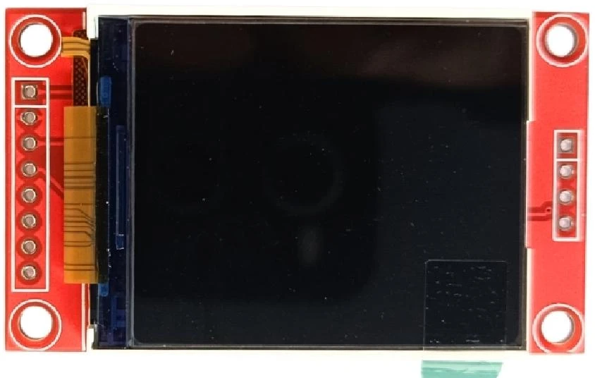
The 1.8-inch ST7735 TFT display is a small, full-color screen that’s widely used in Arduino projects and other embedded systems. It uses the ST7735 driver IC, which controls the display through the SPI communication interface — allowing fast data transfer between the Arduino and the screen.
This 1.8-inch TFT module offers a resolution of 128×160 pixels, providing a clear and colourful output for its size. It can display up to 65,000 colors (16-bit color depth), which makes it suitable for showing not only text and shapes but also small bitmap images or icons.
Although the display works on 3.3V logic, it can easily interface with 5V Arduino boards such as the Uno, Nano, or Mega using proper level shifting or resistor dividers. Its compact design and low power usage make it ideal for portable or handheld projects.
ST7735 Specifications and Features
Here are the main specifications and key features of the 1.8-inch ST7735 TFT display:
- Display Size: 1.8 inches (diagonal)
- Resolution: 128 × 160 pixels
- Driver IC: ST7735
- Interface: SPI (Serial Peripheral Interface)
- Color Depth: 16-bit (65K colors)
- Operating Voltage: 3.3V (some modules include a 5V-compatible regulator)
- Backlight: Built-in white LED
- Viewing Angle: Up to 160° (for IPS variants)
- Refresh Rate: Suitable for smooth animations and graphics
- Compact Size: Lightweight and easy to mount on breadboards or small enclosures
This module combines bright color output, simple wiring, and low power consumption, which makes it one of the most popular small TFT screens for Arduino users. It’s powerful enough to show sensor data, graphs, menus, or even small images from an SD card.
Why Use ST7735 with Arduino?
The 1.8-inch ST7735 TFT is an excellent choice for Arduino projects because of its SPI interface, great color quality, and readily available libraries. It allows beginners and advanced users alike to add graphics and color displays to their projects without much effort.
Here’s why the 1.8-inch ST7735 works so well with Arduino:
- Simple SPI wiring – requires only a few pins for communication.
- Vibrant 16-bit color display – ideal for text, gauges, and icons.
- Compact and affordable – fits perfectly in small projects.
- Fully supported by Adafruit’s ST7735 and GFX libraries, making coding straightforward.
- Compatible with popular Arduino boards like Uno, Nano, and Mega.
This display is great for IoT dashboards, mini game consoles, sensor monitors, and any project where you want to make your Arduino output visually appealing. Later in this tutorial, we’ll also explore how to display BMP images directly from an SD card, giving you even more creative options.
ST7735 Arduino Wiring, Pinout & Library Setup
Let’s start with the ST7735 Pin description first.
ST7735 Pin Description
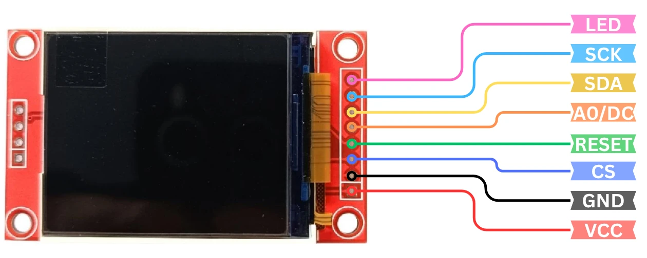
The 1.8-inch ST7735 TFT display communicates with the Arduino using the SPI interface, which makes wiring simple and efficient. Different modules may have slight variations in labeling, but most ST7735 displays include the following pins:
| Pin Name | Description |
|---|---|
| GND | Ground connection (connects to Arduino GND). |
| VCC | Power supply pin. Usually 3.3V, but some modules include a regulator and can accept 5V. |
| SCL (CLK) | Serial Clock pin. Used to synchronize data transfer between Arduino and display. |
| SDA (MOSI) | Serial Data input pin. Carries display data from Arduino to the ST7735. |
| RES (RESET) | Resets the display when pulled LOW. Helps initialize the display during startup. |
| DC (A0) | Data/Command control pin. Tells the display whether data or a command is being sent. |
| CS | Chip Select pin. Enables or disables communication with the display. Active LOW. |
| BL (LED) | Controls the display backlight. Connect to 3.3V (or 5V if supported) for constant brightness, or to a PWM pin for dimming. |
Note:
Some ST7735 modules also include pins like MISO or SD_CS if they have an onboard SD card slot. These are not used for the basic display connection but will be important later when we display images from the SD card.
ST7735 to Arduino Uno Wiring Diagram
To connect the 1.8-inch ST7735 display to an Arduino Uno or Nano, we’ll use the SPI pins. The SPI pins on different Arduino boards may vary slightly, but for Uno and Nano, they are fixed at pins 11 (MOSI), 13 (SCK), and 10 (SS).
The image below shows the connection between Arduino UNO and ST7735 LCD display.
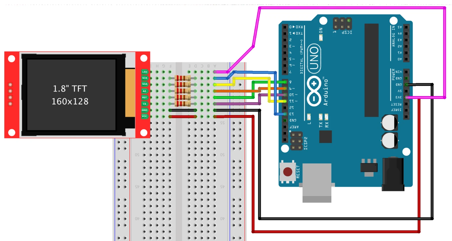
Here’s the connection table:
| ST7735 Pin | Arduino Uno/Nano Pin | Description |
|---|---|---|
| VCC | 5V (or 3.3V if your module doesn’t have a regulator) | Power supply for the display |
| GND | GND | Common ground |
| SCL (CLK) | D13 | SPI Clock |
| SDA (MOSI) | D11 | SPI Data from Arduino to Display |
| RES (RESET) | D8 | Reset control pin |
| DC (A0) | D9 | Data/Command selection |
| CS | D10 | Chip Select pin |
| BL (LED) | 3.3V or D6 (PWM optional) | Backlight control |
Tip: Always check your module’s specifications. Some displays have onboard level shifters, but if yours doesn’t, use a voltage divider on the SPI lines to protect the 3.3V logic display from 5V signals.
How SPI Communication Works on ST7735
The ST7735 uses SPI (Serial Peripheral Interface) for communication. In this mode, the Arduino acts as the master, and the display acts as the slave. SPI is fast and reliable, making it perfect for transferring display data like pixels, colors, and bitmaps.
Here’s how the SPI wiring works:
- SCL (Clock) synchronizes communication between Arduino and the display.
- SDA (MOSI) sends pixel and command data from Arduino to the display controller.
- CS selects the ST7735 device so multiple SPI devices can share the same bus.
- DC defines whether the incoming byte is a command (LOW) or data (HIGH).
- RESET ensures the display starts in a known state.
For stable performance:
- Keep the SPI wires short to reduce noise.
- Ensure the display is properly powered (preferably from a regulated 3.3V pin).
- If the display flickers or shows distorted colors, lower the SPI speed slightly in your code.
Once the wiring is done correctly, you can move on to setting up the Arduino IDE and libraries to communicate with the display smoothly.
Installing Adafruit ST7735 and GFX Libraries
Before we start displaying text, graphics, or images on the 1.8-inch ST7735 TFT display, we need to set up the Arduino IDE properly. The setup includes installing the right libraries, running a basic test code, and verifying that the display is working as expected.
The easiest way to use the ST7735 display with Arduino is through the Adafruit ST7735 and Adafruit GFX libraries. These libraries handle all the low-level communication with the display and make it easy to draw text, shapes, and bitmaps.
Here’s how to install them:
- Open Arduino IDE on your computer.
- Go to Sketch → Include Library → Manage Libraries…
- In the Library Manager, type “Adafruit ST7735” in the search bar.
- Install the “Adafruit ST7735 and ST7789 Library” by Adafruit.
- Next, search for “Adafruit GFX Library” and install it as well.
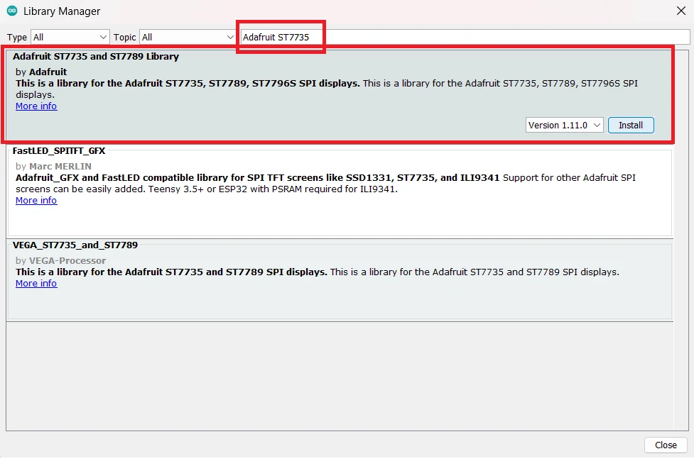
Once installed, you’ll find several example sketches in: File → Examples → Adafruit ST7735 and ST7789 Library
These examples are pre-configured to work with different versions of the ST7735 display, including the 1.8-inch module we’re using.
Tip: Make sure both libraries are from Adafruit to avoid compatibility issues. If you already have older versions installed, update them before proceeding.
Testing with the Graphicstest Example Sketch
After installing the libraries, it’s time to test whether the display is wired and functioning correctly.
Here’s a simple example sketch to verify your setup:
#include <Adafruit_GFX.h>      // Core graphics library
#include <Adafruit_ST7735.h>   // ST7735 display library
#include <SPI.h>               // SPI communication library

// Define pins used for the ST7735
#define TFT_CS     10
#define TFT_DC      9
#define TFT_RST     8

// Create the display object
Adafruit_ST7735 tft = Adafruit_ST7735(TFT_CS, TFT_DC, TFT_RST);

void setup() {
  // Initialize Serial Monitor
  Serial.begin(9600);
  Serial.println("Initializing ST7735 display...");

  // Initialize display
  tft.initR(INITR_BLACKTAB); // Use INITR_BLACKTAB for most 1.8" displays
  tft.fillScreen(ST77XX_BLACK);

  // Display test text
  tft.setTextColor(ST77XX_WHITE);
  tft.setTextSize(2);
  tft.setCursor(10, 20);
  tft.println("ST7735 Test!");
}

void loop() {
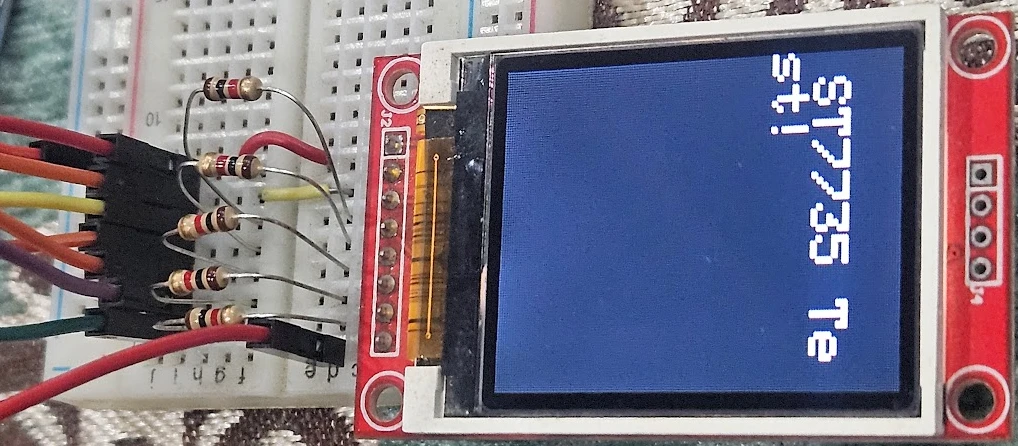
}After Uploading this code to Arduino, the display turns on with a black screen and shows the text “ST7735 Test!” in white.
this is shown in the image below.
Note:
Some 1.8″ displays may use a different tab color such as INITR_GREENTAB or INITR_REDTAB. If the colors appear inverted or the screen is blank, try changing this line accordingly.
tft.initR(INITR_GREENTAB);Experiment with these options until the display output looks correct.
Verifying Setup with Example Sketch
Once the basic test code works, it’s a good idea to run the official Adafruit example sketches to fully verify your setup.
You can access them from:
File → Examples → Adafruit ST7735 and ST7789 Library → graphicstest
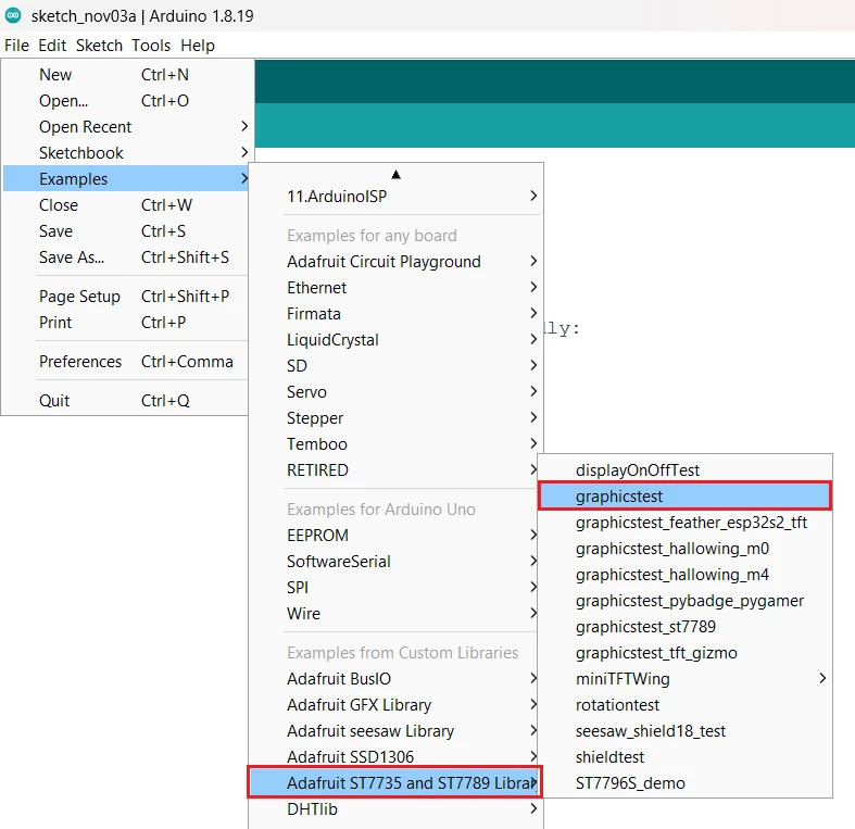
Upload the graphicstest example and watch your display run through several animations — lines, shapes, colors, and text demonstrations.

This confirms that:
- Your wiring is correct.
- The display is powered properly.
- The SPI communication is working without errors.
If you notice flickering, incorrect colors, or a blank screen, double-check your connections and ensure your CS, DC, and RST pins match the pin definitions in the code.
Once everything is working, you’re ready to move on and learn how to display text, shapes, and full-color images on your 1.8-inch ST7735 display.
Displaying Text, Shapes and Colors on ST7735
Once your 1.8-inch ST7735 TFT display is successfully connected and initialized, you can start adding visuals such as text, geometric shapes, and background colors. The Adafruit GFX library makes this process very simple by providing easy-to-use functions for graphics and text rendering.
In this section, we’ll learn how to print text, draw basic shapes, and fill the display with colors.
Printing Text and Numbers on ST7735
Displaying text is one of the simplest and most useful features of the ST7735 display. You can use it to show messages, sensor readings, or any information you want directly on the screen.
Here’s a simple example:
#include <Adafruit_GFX.h>
#include <Adafruit_ST7735.h>
#include <SPI.h>

#define TFT_CS   10
#define TFT_DC    9
#define TFT_RST   8

Adafruit_ST7735 tft = Adafruit_ST7735(TFT_CS, TFT_DC, TFT_RST);

void setup() {
  tft.initR(INITR_BLACKTAB);  // Initialize the display
  tft.fillScreen(ST77XX_BLACK); // Clear the screen

  tft.setTextColor(ST77XX_GREEN); // Set text color
  tft.setTextSize(1); // Set text size
  tft.setCursor(10, 20); // Set text position
  tft.println("Hello World!");

  tft.setTextColor(ST77XX_RED); // Set text color
  tft.setTextSize(2); // Set text size
  tft.setCursor(10, 80); // Set text position
  tft.println(123.45); // Print Number
}

void loop() {
}Explanation:
tft.setTextColor()sets the color of the text.tft.setTextSize()adjusts how large the characters appear.tft.setCursor(x, y)sets the starting position for the text.tft.println()prints the text string or number on the display.
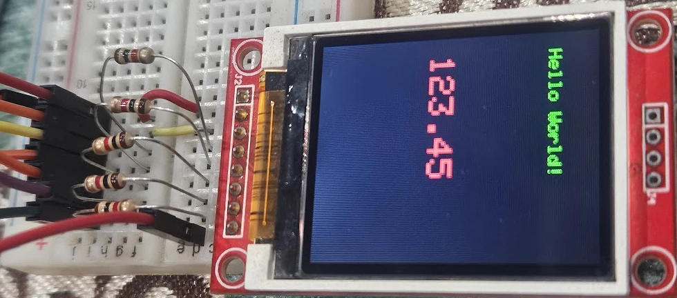
The image below shows the output of printing txt and number on the screen.
Drawing Lines, Rectangles and Circles
The Adafruit GFX library includes functions to draw a variety of shapes, allowing you to create graphical interfaces or visual indicators on your display.
Here are some common drawing functions:
tft.drawLine(0, 0, 127, 159, ST77XX_WHITE);      // Draw a diagonal line
tft.drawRect(10, 10, 60, 40, ST77XX_RED);        // Outline rectangle
tft.fillRect(20, 20, 60, 40, ST77XX_BLUE);       // Filled rectangle
tft.drawCircle(64, 80, 30, ST77XX_YELLOW);       // Outline circle
tft.fillCircle(64, 80, 20, ST77XX_GREEN); // Filled circleExplanation:
drawLine(x0, y0, x1, y1, color)draws a line between two points.drawRect(x, y, width, height, color)makes a rectangle outline.fillRect()fills the rectangle with color.drawCircle(x, y, radius, color)andfillCircle()draw circular shapes.
Note:
The coordinate system starts at the top-left corner (0, 0), with X increasing to the right and Y increasing downward.
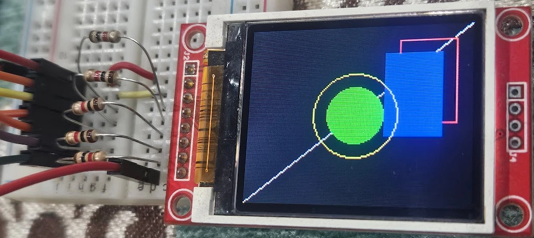
The image below shows the output on the screen with the shapes drawn.
You can combine these shapes to make progress bars, icons, or simple gauges on your display.
Filling the Screen with Solid Colors
Sometimes, you may want to clear the display or fill it with a solid background color. The fillScreen() function makes this easy:
void loop() {
tft.fillScreen(ST77XX_BLUE);  // Fills the display with blue color
delay(1000);
tft.fillScreen(ST77XX_RED);   // Then fills it with red
delay(1000);
tft.fillScreen(ST77XX_BLACK); // Finally clears the screen
delay(1000);
}The GIF below shows the colors on the screen changing every 1 second.

The Adafruit library defines many standard color constants such as:
ST77XX_BLACKST77XX_WHITEST77XX_REDST77XX_GREENST77XX_BLUEST77XX_YELLOWST77XX_CYANST77XX_MAGENTA
You can also create custom colors using the color565() function:
uint16_t myColor = tft.color565(255, 100, 50);  // RGB format
tft.fillScreen(myColor);Tip: The RGB values range from 0–255 each, giving you access to over 65,000 color combinations.
By combining text, shapes, and colors, you can easily design a clean and informative user interface for your Arduino projects. In the next section, we’ll take it a step further, learning how to display images from an SD card on the ST7735 screen.
Displaying BMP Images from SD Card on ST7735
One of the most impressive features of the 1.8-inch ST7735 TFT display is its ability to display bitmap (BMP) images directly from an SD card. This allows you to show logos, icons, or even small photos on your Arduino-based projects, perfect for dashboards, menu screens, or startup animations.
In this section, we’ll go through everything step-by-step: connecting the SD card module, preparing your BMP files, and displaying them on the TFT screen.
If you’re new to using SD cards with Arduino, check out this detailed guide first: Interface SD Card with Arduino using SPI.
Wiring the SD Card Module with ST7735
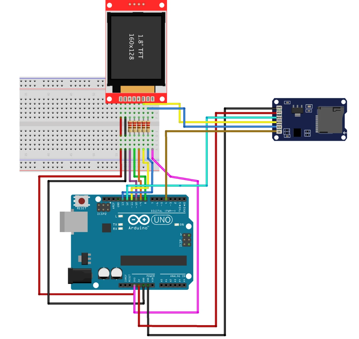
Most ST7735 display boards either include a built-in microSD card slot or require you to connect an external SD card module via SPI. The SD card also communicates over SPI, which means it shares the same MOSI, MISO, and SCK lines with the display.
Here’s how you can connect the SD card module to the Arduino Uno/Nano:
| SD Card Module Pin | Arduino Pin | Description |
|---|---|---|
| VCC | 5V | Power supply for SD module |
| GND | GND | Common ground |
| MOSI | D11 | Master Out Slave In (shared with ST7735) |
| MISO | D12 | Master In Slave Out |
| SCK | D13 | SPI Clock (shared with ST7735) |
| CS (Chip Select) | D4 | Separate CS pin for SD card |
Important: Both the ST7735 and SD card module use SPI, but each must have its own CS (Chip Select) pin. For example, use D10 for ST7735_CS and D4 for SD_CS.
Your wiring should look something like this:
- ST7735 CS → D10
- ST7735 DC → D9
- ST7735 RST → D8
- SD Card CS → D4
- MOSI (D11), MISO (D12), SCK (D13) shared between both.
The image below shows the connection between ST7735 (with SD card) and Arduino UNO.
Preparing BMP Images for the ST7735
The ST7735 library supports displaying 24-bit BMP images directly from the SD card.
Before loading images, make sure to format and prepare your SD card properly:
- Format the SD Card
- Use FAT32 format (recommended for cards up to 32GB).
- You can use your computer’s file manager or the SD Card Formatter tool.
- Prepare Your BMP Images
- Image format: .bmp (24-bit)
- Resolution: Should be 128×160 pixels or smaller (depending on your display’s orientation).
- Save images in bitmap format (not JPEG or PNG) using tools like MS Paint or GIMP.
- Example: Save your image as
image.bmp
- Copy Images to SD Card
- Place your BMP files in the root directory of the SD card for easy access.
- Example:
image1.bmp logo.bmp
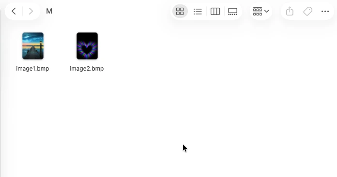
The image below shows the image files stored in the SD card. We will display these 2 images on the ST7735.
Tip: Large BMP files or incorrect bit depths (like 32-bit) won’t display properly. Always save in 24-bit uncompressed BMP format.
BMP Image Display Code and Explanation
Once your SD card and images are ready, you can use Adafruit’s built-in example to display them on your ST7735 display.
Here’s a basic code example:
#include <Adafruit_GFX.h>
#include <Adafruit_ST7735.h>
#include <SPI.h>
#include <SD.h>

#define TFT_CS   10
#define TFT_DC    9
#define TFT_RST   8
#define SD_CS     4

Adafruit_ST7735 tft = Adafruit_ST7735(TFT_CS, TFT_DC, TFT_RST);

void setup() {
  Serial.begin(9600);
  tft.initR(INITR_BLACKTAB);
  tft.fillScreen(ST77XX_BLACK);


  // Initialize SD card
  if (!SD.begin(SD_CS)) {
    Serial.println("SD Card initialization failed!");
    return;
  }
  Serial.println("SD Card initialized.");
}

void loop() {
    // Display BMP image
  bmpDraw("image1.bmp", 0, 0);
  delay(2000);
  bmpDraw("image2.bmp", 0, 0);
  delay(2000);
}

void bmpDraw(char *filename, uint8_t x, uint8_t y) {
  File bmpFile;
  int bmpWidth, bmpHeight;
  uint8_t bmpDepth;
  uint32_t bmpImageoffset;
  uint32_t rowSize;
  uint8_t sdbuffer[3*20]; // RGB buffer
  uint8_t buffidx = sizeof(sdbuffer);
  boolean goodBmp = false;
  boolean flip = true;
  int w, h, row, col;
  uint8_t r, g, b;

  if((x >= tft.width()) || (y >= tft.height())) return;
  bmpFile = SD.open(filename);
  if (!bmpFile) {
    Serial.println("File not found");
    return;
  }

  if (read16(bmpFile) == 0x4D42) { // BMP signature
    read32(bmpFile); read32(bmpFile);
    bmpImageoffset = read32(bmpFile);
    read32(bmpFile);
    bmpWidth  = read32(bmpFile);
    bmpHeight = read32(bmpFile);
    if(read16(bmpFile) == 1 && (bmpDepth = read16(bmpFile)) == 24 && read32(bmpFile) == 0) {
      goodBmp = true;
      rowSize = (bmpWidth * 3 + 3) & ~3;
      if(bmpHeight < 0) { bmpHeight = -bmpHeight; flip = false; }
      w = bmpWidth; h = bmpHeight;
      tft.setAddrWindow(x, y, x+w-1, y+h-1);
      for (row=0; row<h; row++) {
        bmpFile.seek(bmpImageoffset + (flip ? (bmpHeight - 1 - row) * rowSize : row * rowSize));
        buffidx = sizeof(sdbuffer);
        for (col=0; col<w; col++) {
          if (buffidx >= sizeof(sdbuffer)) {
            bmpFile.read(sdbuffer, sizeof(sdbuffer));
            buffidx = 0;
          }
          b = sdbuffer[buffidx++];
          g = sdbuffer[buffidx++];
          r = sdbuffer[buffidx++];
          tft.pushColor(tft.color565(r,g,b));
        }
      }
    }
  }
  bmpFile.close();
}

uint16_t read16(File &f) {
 uint16_t result;
 ((uint8_t *)&result)[0] = f.read();
 ((uint8_t *)&result)[1] = f.read();
 return result;
}
uint32_t read32(File &f) {
  uint32_t result;
  ((uint8_t *)&result)[0] = f.read();
  ((uint8_t *)&result)[1] = f.read();
  ((uint8_t *)&result)[2] = f.read();
  ((uint8_t *)&result)[3] = f.read();
  return result;
}Upload this code, and you should see the BMP images displayed on the ST7735 screen, changing every 1 second. This is shown in the GIF below.

Tip: If your image looks flipped or stretched, check its pixel dimensions and color depth. Also, ensure the filename and extension match exactly (e.g., image1.bmp, not Image1.BMP).
Common SD Card Errors and Fixes
Here are some common issues you might face while displaying images — and how to fix them:
- SD Card initialization failed!
→ Check wiring of the SD_CS pin, ensure proper power supply, and confirm that the card is FAT32 formatted. - Blank or distorted image
→ The image is not in 24-bit BMP format or has an incorrect resolution. - File not found error
→ Ensure the filename is exact, including the lowercase.bmpextension. - Display flickering or resetting
→ Power supply may be insufficient. Use a stable 5V source with adequate current. - SPI conflicts between display and SD card
→ Double-check that both modules have separate CS pins and the SPI lines are not swapped.
ST7735 Arduino TFT Display: Frequently Asked Questions
Conclusion
At this point you have a fully working ST7735 setup: the display is wired, the library is installed, you can render text and shapes in 65K colors, and you can load and display BMP images from an SD card. That's a solid foundation for a wide range of Arduino projects — sensor dashboards, menu systems, startup splash screens, or simple image slideshows.
Two things worth keeping in mind as you go further. First, the SD card and display share the same SPI bus — every time you add another SPI device, make sure it has its own dedicated CS pin or you'll get bus conflicts that are frustrating to debug. Second, if image loading feels slow, the bottleneck is almost always the SD card quality and SPI clock speed — use a Class 10 or UHS-I card and set the SPI speed as high as your wiring allows.
If you need a larger color touchscreen on the same SPI bus, ILI9341 with Arduino and touch is the direct upgrade — same SPI principle, more pixels, touch input. If you want to combine your ST7735 display with a real-time clock to show a live clock face, DS3231 RTC with Arduino pairs naturally with this tutorial. And if you're interested in storing images or data without an SD card, W25Q Flash Memory with Arduino and AT25C256 EEPROM with Arduino are good next reads.
Download ST7735 Arduino TFT Project Files
Complete Arduino sketches for ST7735 text and shape display, color fill, and BMP image loading from SD card — includes sample BMP images and all tested code for Arduino Uno. Free to download — support the work if it helped you.
Browse More Arduino Display Tutorials

SSD1306 Arduino OLED Tutorial: I2C Wiring, Text, Bitmaps & Animations
Arduino SH1106 OLED Tutorial: I2C Wiring, Text, Bitmaps & Animations
How to Interface MAX7219 7 Segment Display with Arduino | Display Text, Scrolling Message, and Time
Arduino ST7920 Tutorial (128×64 LCD): Wiring, Setup, U8g2, and Text Display Guide
Arduino ST7920 Display Graphics Guide: Shapes, Icons, Bitmaps, and UI Design

Subscribe
Login
0 Comments
Newest

