
Home ▸ Arduino ▸ Modules Interfacing ▸
Updated On: May 4, 2026
DS3231 Arduino Tutorial: Real-Time Clock with LCD1602, Alarms & Temperature
The DS3231 is the most accurate RTC module you can add to an Arduino project. Unlike the DS1307 which relies on an external crystal that drifts with temperature, the DS3231 has a built-in temperature-compensated oscillator that keeps time to within a few minutes per year — and keeps running on its onboard CR2032 battery even when the Arduino is powered off.
In this tutorial you’ll learn how to wire the DS3231 to an Arduino Uno, install the RTClib and LiquidCrystal_I2C libraries, set the time both manually and using compile-time, read time and date, display a live clock on a 16×2 I2C LCD, read the onboard temperature sensor, configure Alarm 1 to trigger an LED on the SQW pin, and enable square wave output at 1 Hz, 1 kHz, 4 kHz, or 8 kHz. Every section includes a complete working sketch. The project files are available to download at the bottom of the page.
Both the DS3231 and the LCD1602 communicate over I2C, so the entire circuit uses just two shared data wires. If you haven’t used an I2C LCD before, LCD1602 I2C with Arduino is a good starting point. For other I2C modules in this series, see DS1307 RTC with Arduino, AT25C256 EEPROM with Arduino, Interface SD Card with Arduino, and W25Q Flash Memory with Arduino.

What is the DS3231 RTC Module?
The DS3231 is a Real-Time Clock (RTC) module designed for precise timekeeping. It keeps track of seconds, minutes, hours, day, date, month, and year. Unlike many other RTC modules, the DS3231 uses a temperature-compensated crystal oscillator. This makes it extremely accurate and stable in all weather conditions. It also has a small backup battery that allows it to continue running even when your Arduino is turned off.
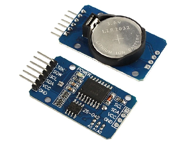
Because of its accuracy and reliability, the DS3231 is widely used in clocks, data loggers, and IoT projects. It communicates over the I2C bus, so it only needs two wires, making it perfect for beginners and advanced users.
DS3231 Features: TCXO, Alarms, Temperature & SQW Output
- High accuracy: The DS3231 has a built-in temperature-compensated crystal oscillator (TCXO). This helps it keep accurate time across various temperatures.
- I2C communication: It communicates using the I2C protocol, so wiring is simple and uses only two pins (SDA and SCL).
- Battery backup: The onboard CR2032 cell keeps the clock running during power loss.
- Calendar function: It provides seconds, minutes, hours, day, date, month and year information, along with leap-year compensation.
- Alarm functionality: You can set one or two alarms for timers, reminders, or triggers.
- Built-in temperature sensor: The DS3231 also includes a digital temperature sensor with ±3°C accuracy.
- Square wave output: It can generate 1Hz, 4kHz, 8kHz, or 32kHz square wave signals.
DS3231 vs DS1307: Key Differences
The DS1307 is an older and less accurate RTC module. The DS3231 is preferred because:
- Much higher accuracy: DS1307 depends on an external crystal, which drifts with temperature. The DS3231’s internal TCXO keeps the clock accurate to a few minutes per year.
- Wider voltage range: DS3231 works from 2.3V to 5.5V. DS1307 usually requires 5V.
- Built-in temperature sensor: DS1307 does not have this feature.
- Stable performance in changing temperatures: DS1307 can drift a lot in cold or hot environments. DS3231 stays stable.
- Better long-term reliability: DS3231 has proven to be more consistent in long-running projects.
Overall, the DS3231 is the best choice for Arduino clocks, IoT nodes, and data logging projects.
Common Applications of DS3231 with Arduino
The DS3231 module is used in many real-world Arduino applications. Some popular examples include:
- Digital clocks: Display time on LCDs or OLEDs.
- Data loggers: Record sensor values with accurate timestamps.
- IoT weather stations: Sync time for sending data at fixed intervals.
- Home automation: Trigger tasks at exact times.
- Alarm systems: Use the alarm pins to trigger buzzers or relays.
- Attendance systems: Time-stamped logs for RFID or keypad entries.
- Timers and reminders: Ideal for periodic tasks like watering systems.
DS3231 Wiring, Pinout & Library Setup
Before working with the DS3231 RTC, it is important to understand its pinout and how it connects to the Arduino. The DS3231 communicates over the I2C bus, so wiring is very simple. You only need two data lines along with power. The LCD1602 I2C display also uses the same bus, which makes the whole setup neat and easy to expand.
DS3231 Pin Description
The DS3231 module usually has 6 pins. The image below shows the pinout of the DS3231 module.
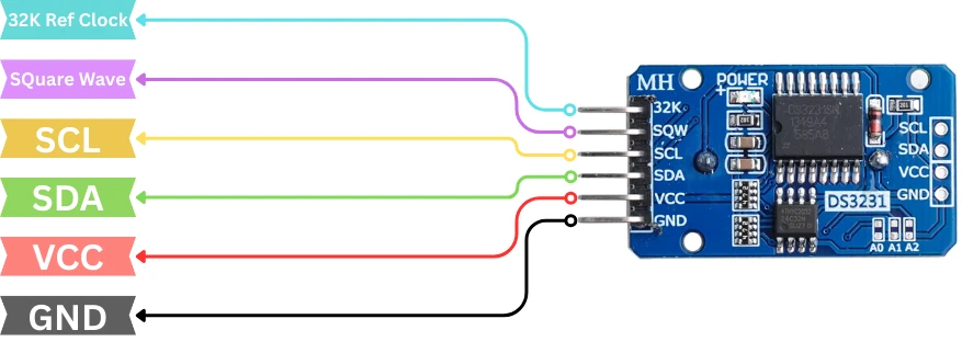
Here is the pinout in a clear table:
| Pin Name | Function | Description |
|---|---|---|
| VCC | Power | Connects to 3.3V or 5V to power the module |
| GND | Ground | Connects to Arduino GND |
| SDA | I2C Data | Transfers data between DS3231 and Arduino |
| SCL | I2C Clock | Provides the clock signal for I2C communication |
| 32K | 32kHz Output | Outputs a stable 32kHz square wave (optional) |
| SQW | Alarm/Square Wave | Used for alarms or square wave output (optional) |
Wiring DS3231 and LCD1602 I2C to Arduino Uno
Connecting the DS3231 to an Arduino UNO is very easy. The module uses the I2C pins of the Arduino.
Here is the wiring:
- DS3231 VCC → 5V
- DS3231 GND → GND
- DS3231 SDA → A4
- DS3231 SCL → A5
The pins A4 and A5 are default I2C pins on the UNO. Keep the wires short for stable I2C communication.
Adding LCD1602 I2C to the Same Bus
The LCD1602 I2C display also uses the I2C bus, so it connects to the same SDA and SCL pins.
Connection:
- LCD SDA → A4
- LCD SCL → A5
- LCD VCC → 5V
- LCD GND → GND
Both DS3231 and LCD1602 will share the same two lines (SDA and SCL). Since each device has its own I2C address, they work without conflict.
For a detailed LCD1602 I2C tutorial, you can check your earlier post on Controllerstech.
Complete Circuit Diagram
The image below shows the wiring connection between DS3231 RTC module, LCD1602 I2C and Arduino.
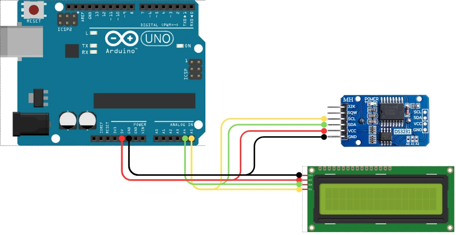
Here is the final wiring in tabular form for better clarity:
| Arduino UNO | DS3231 RTC | LCD1602 I2C |
|---|---|---|
| 5V | VCC | VCC |
| GND | GND | GND |
| A4 (SDA) | SDA | SDA |
| A5 (SCL) | SCL | SCL |
Installing RTClib and LiquidCrystal_I2C Libraries
To work with the DS3231 RTC module, we need the right Arduino libraries. These libraries make it easy to set the time, read the time, and use all the functions of the RTC. We also need the LCD1602 I2C library because we will display the real-time clock on the LCD. Once both libraries are installed, we can start testing simple example codes to make sure everything works.
Installing “RTClib” Library
The RTClib library is one of the most popular libraries for DS3231. It provides simple functions to read and set the time.
Follow these steps:
- Open Arduino IDE
- Go to Sketch → Include Library → Manage Libraries
- In the search bar, type RTClib
- Install the library published by Adafruit
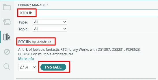
This library supports DS1307, DS3231, and other RTC modules, so it works perfectly for this tutorial.
Installing the LiquidCrystal_I2C Library
Before writing the code, install the LiquidCrystal_I2C library:
- Open Arduino IDE.
- Go to Sketch → Include Library → Manage Libraries.
- Search for “LiquidCrystal_I2C”.
- Install the version by Frank de Brabander or Marco Schwartz.
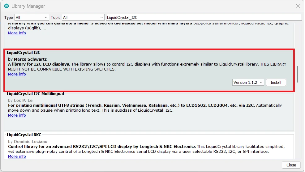
Testing the Library Examples
After installing both libraries, it is a good idea to test the example codes.
- Open Arduino IDE
- Go to File → Examples → RTClib
- Run the ds3231 example
- Check the serial monitor to confirm the date and time readings
Next, test the LCD:
- Go to File → Examples → LiquidCrystal_I2C
- Upload the HelloWorld example
- Make sure the LCD shows the text
DS3231 Arduino Examples: Time, Alarms & Temperature
Before using the DS3231 RTC in your project, you must set the correct time and date. The DS3231 stores this information in its internal registers and keeps running even when the Arduino is powered off, thanks to its backup battery. You can set the time manually, or you can let the Arduino automatically set it using your computer’s compile time. Both methods are simple and supported by the RTClib library.
Setting DS3231 Time: Manual and Compile-Time Methods
Manual Setting
You can set the time and date by entering the values directly in the code. This is useful when you want full control or when your project needs a specific starting time.
#include <Wire.h>
#include "RTClib.h"

RTC_DS3231 rtc;

void setup() {
  Serial.begin(9600);
  Wire.begin();

  if (!rtc.begin()) {
    Serial.println("Couldn't find RTC");
    while (1);
  }

  // Manually set the date and time (Year, Month, Day, Hour, Minute, Second)
  rtc.adjust(DateTime(2025, 1, 1, 12, 0, 0));

  Serial.println("RTC time set manually!");
}

void loop() {
}Explanation:
- We include Wire and RTClib.
- We start the RTC and check if it’s connected.
rtc.adjust()sets the time using the DateTime format.- This time stays stored in the DS3231 until you change it again.
Compile Time Setting
This method sets the RTC to the computer’s exact time at the moment the code is uploaded. It is quick and very convenient.
#include <Wire.h>
#include "RTClib.h"

RTC_DS3231 rtc;

void setup() {
  Serial.begin(9600);
  Wire.begin();

  if (!rtc.begin()) {
    Serial.println("RTC not found");
    while (1);
  }

  // Set RTC using the compile time
  rtc.adjust(DateTime(F(__DATE__), F(__TIME__)));

  Serial.println("RTC updated using compile time!");
}

void loop() {
}Explanation:
__DATE__and__TIME__are built-in macros.- They read your computer’s real time at compilation.
- Upload the code immediately after compiling for best accuracy.
Explanation of Time and Date Functions
The RTClib library provides simple functions to work with the DS3231 time and date.
Here are the most useful ones:
| Function | Description |
|---|---|
rtc.begin() | Starts communication with the DS3231 |
rtc.adjust(DateTime(...)) | Sets the time and date |
rtc.now() | Reads the current time from DS3231 |
now.year() / now.month() / now.day() | Extracts date values |
now.hour() / now.minute() / now.second() | Extracts time values |
now.dayOfTheWeek() | Returns day of the week (0–6) |
now.unixtime() | Returns Unix timestamp |
Reading Time and Date from DS3231
Once the time is set on the DS3231, you can read it anytime using simple functions from the RTClib library. The RTC keeps running even when the Arduino is off, so every time your project starts, you can instantly read accurate time and date. In this section, we will read the live clock values and later display them on the LCD1602 I2C.
Code to Read Time and Date
Below is the simplest code to read the current time and date from the DS3231 and print them on the Serial Monitor:
#include <Wire.h>
#include "RTClib.h"

RTC_DS3231 rtc;

void setup() {
  Serial.begin(9600);
  Wire.begin();

  if (!rtc.begin()) {
    Serial.println("RTC not found!");
    while (1);
  }

  Serial.println("Reading time from DS3231...");
}

void loop() {
  DateTime now = rtc.now();

  Serial.print(now.hour());
  Serial.print(":");
  Serial.print(now.minute());
  Serial.print(":");
  Serial.print(now.second());
  Serial.print("  ");

  Serial.print(now.day());
  Serial.print("/");
  Serial.print(now.month());
  Serial.print("/");
  Serial.print(now.year());

  Serial.println();

  delay(1000);
}Explanation:
rtc.now()reads the current time.- The values are printed as HH:MM:SS and DD/MM/YYYY.
delay(1000)updates the print every second.
Breaking Down RTC Read Function
The rtc.now() function returns a DateTime object. You can extract individual values easily:
| Function | Returns |
|---|---|
now.hour() | Current hour (0–23) |
now.minute() | Current minute |
now.second() | Current seconds |
now.day() | Day of the month |
now.month() | Month number |
now.year() | Full year |
now.dayOfTheWeek() | Day index (0 = Sunday) |
These functions make it simple to show the clock on LCD or use the time for automation tasks.
Example:
DateTime now = rtc.now();
int hour = now.hour();
int minute = now.minute();
int second = now.second();Handling 12-Hour and 24-Hour Format
The DS3231 works internally in 24-hour format, but you can easily convert it to 12-hour AM/PM format in your code.
int hour24 = now.hour();
int hour12 = hour24 % 12;
if (hour12 == 0) hour12 = 12;

String period = (hour24 >= 12) ? "PM" : "AM";

Serial.print(hour12);
Serial.print(":");
Serial.print(now.minute());
Serial.print(":");
Serial.print(now.second());
Serial.print(" ");
Serial.println(period);How it works:
% 12converts 24-hour to 12-hour format.- If the result is 0, we set it to 12 (for midnight/noon).
- The AM/PM value is selected based on hour24.
Displaying Live Clock on LCD1602 I2C
When working with the DS3231 Real-Time Clock module, the final and most useful step is to show the live time and date on a display. In this tutorial, we will use the LCD1602 I2C display, which requires only two wires (SDA and SCL).
If you have followed my previous tutorial on LCD1602 I2C, the process will feel very familiar. Here, we will combine the DS3231 data with the LCD to create a simple real-time clock output.
Below is the complete example that reads both date and time from the DS3231 and prints them to the LCD1602 I2C in real time.
Complete Code: Display Date + Time on LCD1602 (I2C)
#include <Wire.h>
#include "RTClib.h"
#include <LiquidCrystal_I2C.h>

RTC_DS3231 rtc;
LiquidCrystal_I2C lcd(0x27, 16, 2);

// -------------------- SETTINGS --------------------
// Enable only ONE of the following:
#define AUTO_TIME_SET     1   // Set RTC from system compile time
#define MANUAL_TIME_SET   0   // Set RTC to manually defined values

// Manual time setup (works only when MANUAL_TIME_SET = 1)
int manualYear   = 2025;
int manualMonth  = 1;
int manualDate   = 15;
int manualHour   = 10;
int manualMinute = 45;
int manualSecond = 0;
// ---------------------------------------------------

void setup() {
  Serial.begin(9600);
  Wire.begin();

  if (!rtc.begin()) {
    Serial.println("Couldn't find RTC");
    while (1);
  }

#if AUTO_TIME_SET
  rtc.adjust(DateTime(F(__DATE__), F(__TIME__)));
#endif

#if MANUAL_TIME_SET
  rtc.adjust(DateTime(manualYear, manualMonth, manualDate,
                      manualHour, manualMinute, manualSecond));
#endif

  lcd.begin(16, 2);
  lcd.backlight();
}

void loop() {
  DateTime now = rtc.now();

  // Format Date: DD/MM/YYYY
  char dateBuffer[17];
  snprintf(dateBuffer, sizeof(dateBuffer), "%02d/%02d/%04d",
           now.day(), now.month(), now.year());

  // Format Time: HH:MM:SS
  char timeBuffer[17];
  snprintf(timeBuffer, sizeof(timeBuffer), "%02d:%02d:%02d",
           now.hour(), now.minute(), now.second());

  // Display on LCD
  lcd.setCursor(0, 0);
  lcd.print(dateBuffer);

  lcd.setCursor(0, 1);
  lcd.print(timeBuffer);

  delay(1000);
}Explanation:
1. Library Imports
#include <Wire.h>
#include "RTClib.h"
#include <LiquidCrystal_I2C.h>These libraries handle I2C communication, the DS3231 RTC module, and the 16×2 I2C LCD.
2. Object Creation
RTC_DS3231 rtc;
LiquidCrystal_I2C lcd(0x27, 16, 2);rtc→ creates an RTC object for DS3231.lcd→ creates an LCD object at I2C address0x27, with a 16×2 display size.
3. Settings Section
#define AUTO_TIME_SET 1
#define MANUAL_TIME_SET 0Only one method can be active:
AUTO_TIME_SET = 1sets the RTC time from the computer’s compile time.MANUAL_TIME_SET = 1sets custom date/time from user-defined values.
Manual time values:
int manualYear = 2025;
...
...These are used only when manual mode is enabled.
4. Setup Function
A. Initialize Serial & I2C
Serial.begin(9600);
Wire.begin();Starts serial communication and enables I2C.
B. Initialize RTC
if (!rtc.begin()) {
Serial.println("Couldn't find RTC");
while (1);
}Checks if the DS3231 is connected. If not, the code stops here.
C. Select Time Setting Mode
#if AUTO_TIME_SET
rtc.adjust(DateTime(F(__DATE__), F(__TIME__)));
#endifSets RTC using the system’s compile date/time.
#if MANUAL_TIME_SET
rtc.adjust(DateTime(manualYear, manualMonth, manualDate,
manualHour, manualMinute, manualSecond));
#endifSets RTC using the manual values.
D. Initialize LCD
lcd.begin(16, 2);
lcd.backlight();Starts the 16×2 LCD and turns on its backlight.
5. Loop Function
A. Read Current Time
DateTime now = rtc.now();Fetches current date and time from the DS3231 module.
B. Format Date
char dateBuffer[17];
snprintf(dateBuffer, sizeof(dateBuffer), "%02d/%02d/%04d",
now.day(), now.month(), now.year());Creates a string like: 15/01/2025
C. Format Time
char timeBuffer[17];
snprintf(timeBuffer, sizeof(timeBuffer), "%02d:%02d:%02d",
now.hour(), now.minute(), now.second());Creates a string like: 10:45:00
D. Display on LCD
lcd.setCursor(0, 0);
lcd.print(dateBuffer);
lcd.setCursor(0, 1);
lcd.print(timeBuffer);Line 1 : Date
Line 2 : Time
E. Update Every Second
delay(1000);Refreshes the display once per second.
Output
The GIF below shows the current time and date printed on the LCD1602.

Reading DS3231 Temperature on LCD1602
In this section, we will display the DS3231 temperature reading on a 16×2 I2C LCD, along with the current time.
The code includes both automatic time setting (based on the compile time) and manual time setting, so you can enable either method depending on your requirement.
This example uses the following libraries:
Wire.hRTClib.hLiquidCrystal_I2C.h
Complete Code: Temperature and Time Display on LCD
#include <Wire.h>
#include <RTClib.h>
#include <LiquidCrystal_I2C.h>
RTC_DS3231 rtc;
LiquidCrystal_I2C lcd(0x27, 16, 2);
// -------------------- SETTINGS --------------------
// Enable only ONE of the following:
#define AUTO_TIME_SET 1 // Set RTC from system compile time
#define MANUAL_TIME_SET 0 // Set RTC to manually defined values
// Manual time setup (works only when MANUAL_TIME_SET = 1)
int manualYear = 2025;
int manualMonth = 1;
int manualDate = 15;
int manualHour = 10;
int manualMinute = 45;
int manualSecond = 0;
// ---------------------------------------------------
void setup() {
Wire.begin();
lcd.init();
lcd.backlight();
lcd.setCursor(0, 0);
lcd.print("Initializing...");
delay(1500);
if (!rtc.begin()) {
lcd.clear();
lcd.print("RTC NOT FOUND");
while (1);
}
#if AUTO_TIME_SET
rtc.adjust(DateTime(F(__DATE__), F(__TIME__)));
#endif
#if MANUAL_TIME_SET
rtc.adjust(DateTime(manualYear, manualMonth, manualDate,
manualHour, manualMinute, manualSecond));
#endif
lcd.clear();
}
void loop() {
DateTime now = rtc.now();
float tempC = rtc.getTemperature();
// Display the time on the first line
lcd.setCursor(0, 0);
if (now.hour() < 10) lcd.print("0");
lcd.print(now.hour());
lcd.print(":");
if (now.minute() < 10) lcd.print("0");
lcd.print(now.minute());
lcd.print(":");
if (now.second() < 10) lcd.print("0");
lcd.print(now.second());
// Display temperature on the second line
lcd.setCursor(0, 1);
lcd.print("Temp: ");
lcd.print(tempC);
lcd.print((char)223); // Degree symbol
lcd.print("C");
delay(500);
}Explanation
- The LCD is initialized using the I2C address
0x27. - The code checks if the DS3231 is detected on the I2C bus.
- Depending on the user selection, either the automatically generated compile-time is loaded into the RTC, or the manually entered values are used.
- The loop continuously updates the LCD with the current time in HH:MM:SS format.
- The temperature value from the DS3231 sensor is displayed on the second line of the LCD.
Output
The GIF below shows the Time and Temperature data printed on the LCD1602.

Alarm 1 with LED on SQW Pin
The DS3231 has a dedicated SQW/INT pin that becomes active whenever an alarm condition is met. This pin is an open-drain output, which means it pulls LOW during the alarm and stays HIGH when idle.
Because of this, you can connect a low-current LED directly to this pin using a pull-up resistor. The LED will automatically turn ON when the alarm triggers.
In this example:
- The LCD shows the live time and alarm status.
- Alarm 1 triggers at a specific HH:MM:SS.
- The LED connected to the SQW pin turns ON when the alarm fires.
- The code includes both auto time set and manual time set options.
Wiring the LED to DS3231 SQW Pin
Since SQW is an open-drain, active-low signal, wire the LED as follows:
| Connection | Description |
|---|---|
| LED Anode -> 3.3V | Positive supply |
| LED Cathode -> 220Ω resistor -> SQW pin | Current-limited path to SQW |
The image below shows the wiring for the LED connected to the Alarm pin.
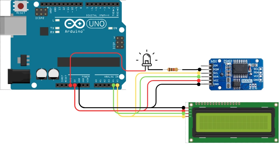
Why this wiring?
- When alarm is inactive: SQW is HIGH, therefore the LED is OFF
- When alarm is active: SQW pulls LOW, therefore LED turns ON
Complete Code: Alarm 1 Trigger
#include <Wire.h>
#include <RTClib.h>
#include <LiquidCrystal_I2C.h>
RTC_DS3231 rtc;
LiquidCrystal_I2C lcd(0x27, 16, 2);
// -------------------- SETTINGS --------------------
// Enable only ONE of the following:
#define AUTO_TIME_SET 1 // Set RTC from system compile time
#define MANUAL_TIME_SET 0 // Set RTC to manually defined values
// Manual time setup (works only when MANUAL_TIME_SET = 1)
int manualYear = 2025;
int manualMonth = 1;
int manualDate = 15;
int manualHour = 10;
int manualMinute = 45;
int manualSecond = 0;
// ---------------------------------------------------
void setup() {
Wire.begin();
lcd.init();
lcd.backlight();
if (!rtc.begin()) {
lcd.print("RTC ERROR!");
while (1);
}
#if AUTO_TIME_SET
rtc.adjust(DateTime(F(__DATE__), F(__TIME__)));
#endif
#if MANUAL_TIME_SET
rtc.adjust(DateTime(manualYear, manualMonth, manualDate,
manualHour, manualMinute, manualSecond));
#endif
// Clear any previous alarms
rtc.clearAlarm(1);
rtc.clearAlarm(2);
// Disable any existing alarms
rtc.disableAlarm(1);
rtc.disableAlarm(2);
// Enable SQW/INT output for alarms
rtc.writeSqwPinMode(DS3231_OFF); // Ensures SQW works in alarm mode
// Set Alarm 1 to trigger at 12:30:00
rtc.setAlarm1(
DateTime(2025, 11, 24, 13, 45, 0),
DS3231_A1_Second | DS3231_A1_Minute | DS3231_A1_Hour
);
lcd.setCursor(0, 0);
DateTime alarm1 = rtc.getAlarm1();
lcd.print("Alarm Set ");
lcd.print(alarm1.hour());
lcd.print(":");
lcd.print(alarm1.minute());
}
void loop() {
DateTime now = rtc.now();
lcd.setCursor(0, 1);
lcd.print(now.hour());
lcd.print(":");
lcd.print(now.minute());
lcd.print(":");
lcd.print(now.second());
// CHECK ALARM TRIGGER
if (rtc.alarmFired(1)) {
lcd.clear();
lcd.setCursor(0, 0);
lcd.print("ALARM TRIGGER!");
// Clear alarm flag
rtc.clearAlarm(1);
delay(2000);
}
delay(500);
}Explanation
Since the rest of the code (RTC initialization, LCD setup, and time formatting) has already been explained above, we will focus only on the alarm functionality in this section.
1. Clear old alarms
rtc.clearAlarm(1);
rtc.clearAlarm(2);Removes any previously triggered alarm flags so the system starts clean.
2. Disable existing alarm settings
rtc.disableAlarm(1);
rtc.disableAlarm(2);Ensures no old alarm rules are active before configuring a new one.
3. Configure SQW/INT pin for alarm mode
rtc.writeSqwPinMode(DS3231_OFF);Disables the square-wave output so the INT/SQW pin can act as an alarm interrupt pin.
4. Set Alarm 1
rtc.setAlarm1(
DateTime(2025, 11, 24, 13, 45, 0),
DS3231_A1_Second | DS3231_A1_Minute | DS3231_A1_Hour
);This schedules an alarm for 13:45:00.
The mode flags mean:
- Match hour
- Match minute
- Match second
The alarm triggers exactly when the time hits 13:45:00, once.
5. Read back and display alarm time
DateTime alarm1 = rtc.getAlarm1();Used to show the programmed alarm on the LCD.
6. Check for alarm trigger
if (rtc.alarmFired(1)) {
lcd.clear();
lcd.print("ALARM TRIGGER!");
rtc.clearAlarm(1);
}alarmFired(1)becomes true the moment the current time matches the alarm.- A message is displayed.
- The alarm flag is cleared so it does not repeat unless reconfigured.
This simple code demonstrates how to set alarms on the DS3231, display time on an I2C LCD, and activate an LED using the SQW alarm output.
Output
The GIF below shows the Alarm triggered on the DS3231.

Enabling Square Wave Output on SQW Pin
The DS3231 can generate a stable and accurate square-wave output on the SQW pin. This signal is very useful in many Arduino projects, especially where you need:
- A precise clock pulse
- Timer generation
- Power-saving wakeups
- External timing reference
- CPU tick replacement
The DS3231 supports multiple square-wave frequencies, and you can select any one depending on your project needs.
Available Square Wave Frequencies
The DS3231 supports:
| Frequency | Description |
|---|---|
| 1 Hz | One pulse per second |
| 1.024 kHz | Medium-speed timing |
| 4.096 kHz | Fast timing pulses |
| 8.192 kHz | Highest available output |
Complete Code: Enabling Square Wave Signal on SQW Pin
This example enables a 1 Hz square wave. You can change the frequency easily (explained below).
The LED connected to SQW will blink at 1 Hz with this code.
#include <Wire.h>
#include <RTClib.h>
#include <LiquidCrystal_I2C.h>
RTC_DS3231 rtc;
LiquidCrystal_I2C lcd(0x27, 16, 2);
// ---------------------- TIME SETTINGS ----------------------
#define AUTO_TIME_SET     1
#define MANUAL_TIME_SET   0
int manualYear = 2025;
int manualMonth = 1;
int manualDate = 15;
int manualHour = 11;
int manualMinute = 10;
int manualSecond = 0;
// ------------------------------------------------------------
void setup() {
Wire.begin();
lcd.init();
lcd.backlight();
lcd.print("Initializing RTC");
delay(1500);
lcd.clear();
if (!rtc.begin()) {
lcd.print("RTC ERROR");
while (1);
}
#if AUTO_TIME_SET
  rtc.adjust(DateTime(F(__DATE__), F(__TIME__)));
#endif
#if MANUAL_TIME_SET
  rtc.adjust(DateTime(manualYear, manualMonth, manualDate,
                      manualHour, manualMinute, manualSecond));
#endif
// Disable alarms
rtc.clearAlarm(1);
rtc.clearAlarm(2);
// ------------------ ENABLE SQUARE WAVE OUTPUT ------------------
rtc.writeSqwPinMode(DS3231_SquareWave1Hz);
// Options:
// DS3231_SquareWave1Hz
// DS3231_SquareWave1kHz
// DS3231_SquareWave4kHz
// DS3231_SquareWave8kHz
// ---------------------------------------------------------------
lcd.clear();
}
void loop() {
DateTime now = rtc.now();
// Display current time
lcd.setCursor(0, 0);
if (now.hour() < 10) lcd.print("0");
lcd.print(now.hour()); lcd.print(":");
if (now.minute() < 10) lcd.print("0");
lcd.print(now.minute()); lcd.print(":");
if (now.second() < 10) lcd.print("0");
lcd.print(now.second());
lcd.setCursor(0, 1);
lcd.print("SQW: 1 Hz Output");
delay(500);
}
Explanation
1. Enabling Square Wave Mode
The key line is:
rtc.writeSqwPinMode(DS3231_SquareWave1Hz);This sets the SQW pin to output a 1 Hz clock signal.
You can change the frequency very easily:
rtc.writeSqwPinMode(DS3231_SquareWave8kHz);2. LED Blinks at 1 Hz
If you connect an LED to SQW (same wiring as the alarm section), it will blink once every second.
Output
The GIF below shows the LED (Connected to SQW pin) blinking every second.

DS3231 Arduino RTC: Frequently Asked Questions
Conclusion
The DS3231 is one of those modules that just works. Wire it up, call rtc.begin(), set the time once using compile-time or manual values, and it will keep running accurately for years on the backup battery without any attention. The examples in this tutorial give you a working foundation for every major DS3231 feature — live clock display, temperature reading, alarm-triggered outputs, and square wave generation.
The most important thing to remember after this tutorial: comment out or remove rtc.adjust() from your code after setting the time once. Leaving it active means the RTC resets to compile time on every upload — a common issue that catches beginners off guard, and already answered in the FAQ below.
From here, a natural next step is the DS1307 Arduino tutorial if you need a simpler, lower-cost RTC for non-temperature-sensitive applications. If you’re building a data logger and need to store the timestamped readings, SD card with Arduino and W25Q Flash memory with Arduino are the next logical pieces. And if you want to add non-volatile storage for settings like your alarm times so they survive power cycles, AT25C256 EEPROM with Arduino covers exactly that.
Download DS3231 Arduino RTC Project Files
Complete Arduino sketches for DS3231 time display on LCD1602 I2C, onboard temperature reading, Alarm 1 with SQW LED trigger, and square wave output — all examples included, tested on Arduino Uno. Free to download — support the work if it helped you.
Browse More Arduino Modules Tutorials
AT25C256 EEPROM with Arduino using I2C – Read, Write, and Store Data Easily

Arduino W25Q Flash Memory Tutorial: Read, Write, and Store Data Efficiently
DS1307 Arduino Tutorial: Interfacing RTC Module with LCD1602 I2C Display
Arduino Passive Buzzer Tutorial: tone(), Alarm, Siren & Music Codes

WS2812 Arduino Tutorial: NeoPixel Ring Wiring, Effects & Animations

Subscribe
Login
0 Comments
Newest

