
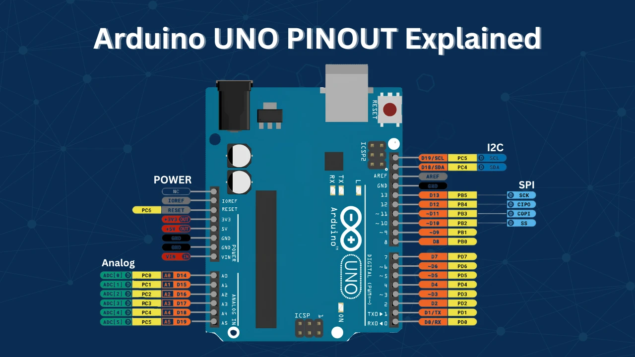
Home ▸ Arduino ▸ Core Tutorials ▸
Updated On: May 29, 2026
Arduino digitalWrite() and digitalRead(): Complete Guide with Examples
digitalWrite() and digitalRead() are the two functions you’ll use in almost every Arduino project. One controls outputs — LEDs, buzzers, relays, motors. The other reads inputs — buttons, switches, sensors. Together they are the foundation of all Arduino GPIO interaction.
In this tutorial, you will learn:
- How
pinMode()works and why it must be called first - How to use
digitalWrite()to control digital outputs - How to use
digitalRead()to read digital inputs - When to use
INPUT_PULLUPinstead of plainINPUT— and why it matters - Output voltage and current limits for Arduino GPIO pins
- A working example: button controls an LED
This is part of the Arduino Core Tutorials series. If you’re new to Arduino I/O, start with the following:
- analogRead() and ADC
- PWM & analogWrite()
- delayMicroseconds()
- external interrupts
- UART serial communication
digitalWrite() — Digital Output Control
Arduino GPIO pins can work as either inputs or outputs. When configured as an output, a pin can drive devices like LEDs, buzzers, relays, and motors. You control the pin state using digitalWrite().
pinMode() for Output
Before using digitalWrite(), you must tell Arduino that the pin is an output. You do this with pinMode() in the setup() function:
void setup() {
  pinMode(13, OUTPUT);       // Configure pin 13 as output
  digitalWrite(13, HIGH);   // Set pin 13 HIGH (5V or 3.3V)
}

void loop() {
}setup() runs once when the Arduino starts. pinMode(13, OUTPUT) sets pin 13 as an output. digitalWrite(13, HIGH) pulls the pin to the board’s supply voltage — 5V on the UNO. If you connect a voltmeter to pin 13 after this, you will measure 5V.
Key rules to follow:
- Always call
pinMode()beforedigitalWrite(). - HIGH = 5V (or 3.3V on 3.3V boards), LOW = 0V.
- Always use a resistor when connecting an LED to protect the pin.
- Never connect high-current devices directly, instead use a relay, transistor, or MOSFET.
Output Voltage and Current Limits
Voltage:
- HIGH = 5V on 5V boards (UNO, Mega, Nano), 3.3V on 3.3V boards (Due, MKR series)
- LOW = 0V (GND)
Never connect one Arduino output pin directly to another output pin, or to the output of a sensor or IC. If two outputs at different voltages are shorted together, excessive current flows and can permanently damage the pin. If you are mixing 3.3V and 5V devices, use a level shifter between them.
Current:
- Maximum per pin: 40 mA (absolute limit — do not rely on this in designs)
- Recommended safe operating current: 20 mA per pin
20 mA is enough to drive a small LED (with a resistor) or a buzzer. For motors, relays, or high-power LEDs, you must use an external driver circuit.
Wiring an LED to Pin 13
Connect the LED’s anode (long leg) to pin 13 through a 330 Ω resistor. Connect the cathode (short leg) directly to GND.
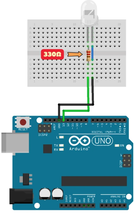
The resistor limits the current through the LED and prevents it from burning out. The Arduino UNO already has an onboard LED on pin 13, but adding an external LED makes the output visible and easier to verify.
LED Blink with digitalWrite()
The code below blinks the LED every 1 second:
#define LED_PIN 13  // LED connected to pin 13

void setup() {
  pinMode(LED_PIN, OUTPUT);       // Set pin 13 as output
}

void loop() {
  digitalWrite(LED_PIN, HIGH);   // Turn LED ON
  delay(1000);                   // Wait 1 second
  digitalWrite(LED_PIN, LOW);    // Turn LED OFF
  delay(1000);                   // Wait 1 second
}
#define LED_PIN 13 gives pin 13 a readable name. If you move the LED to a different pin later, you only change this one line.
setup() runs once and sets pin 13 as an output. The loop() function runs forever — it turns the LED on, waits 1 second, turns it off, waits another second, and repeats.
Output
After uploading the example code to your Arduino, here’s what you should observe:
The LED connected to pin 13 turns ON for 1 second, then OFF for 1 second. This cycle repeats continuously, showing that the digital output pin is working correctly. This confirms that your pin has been correctly configured as OUTPUT using pinMode().
digitalRead() — Digital Input Reading
Arduino pins can also act as digital inputs. In this mode, the pin reads whether a connected device is sending a HIGH or LOW signal. This lets you detect button presses, switch states, and digital sensor outputs.
To set a pin as an input, use pinMode() with INPUT:
void setup() {
  pinMode(2, INPUT);  // Configure pin 2 as input
}

void loop() {
  int buttonState = digitalRead(2);  // Read pin 2
}digitalRead() returns:
HIGH— if the pin is receiving voltage (5V or 3.3V)LOW— if the pin is connected to GND
The floating pin problem: If nothing is connected to an input pin, the pin “floats” — it can randomly read HIGH or LOW. This causes unpredictable behavior. You must either use an external pull-up or pull-down resistor, or use INPUT_PULLUP.
INPUT vs INPUT_PULLUP
INPUT_PULLUP enables the Arduino’s internal pull-up resistor. This keeps the pin at HIGH by default when nothing is driving it. When you press a button that connects the pin to GND, it reads LOW.
pinMode(2, INPUT_PULLUP); // Input with internal pull-up — defaults to HIGH| Feature | INPUT | INPUT_PULLUP |
|---|---|---|
| Default pin state | Floating (unpredictable) | HIGH (stable) |
| External resistor needed | Yes | No |
| Button wiring | Button to GND + pull-down resistor | Button to GND only |
| Risk of false reads | High | Low |
Use INPUT_PULLUP for buttons and switches in most projects. It simplifies wiring and eliminates false reads.
Input Voltage and Current Limits
- HIGH threshold: 3V and above (on 5V boards)
- LOW threshold: below 1.5V (on 5V boards)
- Never apply more than 5V to a 5V board’s input pin — it can permanently damage the Arduino.
Input pins draw only microamps of current, so you can connect buttons, switches, and digital sensors directly without any driver circuit.
Common digital input use cases:
- Buttons and toggle switches — detecting user input
- PIR motion sensors — detecting movement
- IR obstacle sensors — detecting objects
- Limit switches — used in robotics and CNC machines
Wiring a Button to Pin 2
Connect one leg of the push button to pin 2. Connect the other leg to GND. With INPUT_PULLUP, no external resistor is needed.
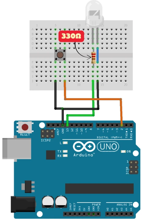
Pin 2 stays HIGH by default. When the button is pressed, pin 2 connects to GND and reads LOW. This is the logic we use in the code below.
Button Controls LED with digitalRead()
This example turns the LED on when the button is pressed, and off when it is released:
const int buttonPin = 2;   // Button connected to pin 2
const int LED_PIN = 13;    // LED connected to pin 13

void setup() {
  pinMode(buttonPin, INPUT_PULLUP);   // Input with internal pull-up
  pinMode(LED_PIN, OUTPUT);           // LED pin as output
}

void loop() {
  int buttonState = digitalRead(buttonPin);  // Read button state

  if (buttonState == LOW) {                  // Button pressed → pin pulled LOW
    digitalWrite(LED_PIN, HIGH);            // Turn LED ON
  } else {                                   // Button released → pin is HIGH
    digitalWrite(LED_PIN, LOW);             // Turn LED OFF
  }
}pinMode(buttonPin, INPUT_PULLUP) enables the internal pull-up, so pin 2 reads HIGH when the button is not pressed. digitalRead(buttonPin) reads the current pin state on every loop cycle.
When the button is pressed, pin 2 connects to GND and reads LOW — the if block runs and turns the LED on. When released, the pin returns to HIGH and the LED turns off.
Output
After uploading the example code to your Arduino, here’s what you should observe:
As you can see in the video, the LED is OFF by default. When the button is pressed, the LED turns ON and it stays ON as long as the button is pressed. On realeasing the button, the LED turns OFF again. This confirms that our code is working well, just as we progra
Tips for Reliable Digital I/O
Debounce buttons in code. Mechanical buttons generate brief electrical noise when pressed or released, causing multiple rapid HIGH/LOW transitions. Add a small delay or use a debounce library to avoid false triggers.
if (digitalRead(buttonPin) == LOW) {
  delay(20);                              // Wait for bounce to settle
  if (digitalRead(buttonPin) == LOW) {   // Confirm still pressed
    // Button is genuinely pressed
  }
}Never leave an input pin floating. Always use INPUT_PULLUP, or connect an external pull-up or pull-down resistor (10 kΩ is common). A floating pin is a source of unpredictable behavior.
Match voltage levels. If your sensor or module runs at 3.3V and your Arduino runs at 5V, use a logic level shifter before connecting them.
Protect outputs with resistors. Always use a current-limiting resistor with LEDs. 220 Ω to 470 Ω works for most 5V projects.
Arduino digitalWrite() and digitalRead(): FAQ
Conclusion
digitalWrite() and digitalRead() are simple functions with a lot of depth once you understand what's happening underneath — why floating pins cause random reads, why INPUT_PULLUP is almost always the right choice for buttons, and why a 330 Ω resistor is required before connecting an LED to any output pin.
From here, the direct next step is PWM and analogWrite() — which builds on the same output pins to give you variable control over brightness and speed rather than just ON/OFF. If your project needs to react to events without blocking the main loop, external interrupts is how you handle button presses without polling inside loop(). And when you need to read analog signals from sensors like potentiometers or temperature sensors, analogRead() and ADC covers the other half of Arduino's I/O system.
Download Arduino digitalWrite() and digitalRead() Project Files
Complete Arduino sketch with LED blink using digitalWrite() and button-controlled LED using digitalRead() with INPUT_PULLUP — ready to upload and test. Free to download — support the work if it helped you.
Browse More Arduino Core Tutorials
Arduino Nano Pinout – Complete Guide with Diagram
Arduino UART Tutorial: Serial Communication, Send, Receive & LED Control
Arduino ADC and analogRead() Explained: Complete Guide with Examples
Arduino I2C Tutorial: Wire Library, Master/Slave, Scanner & Troubleshooting
Arduino delayMicroseconds() Tutorial: Precise Timing, Pulses & Alternatives



Way better than the official documentation. Way better than any other youtube video out there. Simply superb.