Home ▸ Arduino ▸ Core Tutorials ▸
Updated On: June 27, 2026
Arduino External Interrupts Tutorial: attachInterrupt(), ISR, Modes & LED Example
When running code inside the loop(), it cannot react to an external event until the current iteration finishes. For a button press lasting 50 ms, that delay might be imperceptible. For a rotary encoder spinning at speed, a pulse counter, or a motion trigger that fires in microseconds, it is far too slow. External interrupts fix this by pausing the main program the instant a pin changes its state, running a dedicated function, and returning.
In this tutorial you’ll learn exactly what an interrupt is at the hardware level and why it is fundamentally different from polling. Which pins on Uno, Nano, Mega, Leonardo, and Zero support hardware interrupts. How to use attachInterrupt() and detachInterrupt() with all trigger modes. And how to write an Interrupt Service Routine.
This is part of the Arduino Core Tutorials series. Related tutorials are as follows:
- Arduino digitalWrite() & digitalRead() — Complete Guide
- Arduino PWM and analogWrite() Explained
- Arduino ADC and analogRead() — Complete Guide
- Arduino UART Serial Communication Tutorial
- Arduino I2C Tutorial with Wire Library
- Arduino delayMicroseconds() — Precision Timing Guide
For interrupt-based multitasking, the Arduino FreeRTOS tutorials build directly on what you’ll learn here.
How External Interrupts Work
An interrupt is a hardware signal that pauses the main program, runs a special function called an ISR (Interrupt Service Routine), and then returns to exactly where the main program left off. The whole process happens in few microseconds.
Without interrupts, you must poll a pin repeatedly in loop(). Polling misses brief signals if the loop is busy and wastes CPU cycles on constant checking. Interrupts eliminate both problems.
External interrupts are triggered by voltage changes on dedicated hardware pins. These pins are directly wired to the microcontroller’s interrupt logic. Only specific pins support this, not every digital pin qualifies.
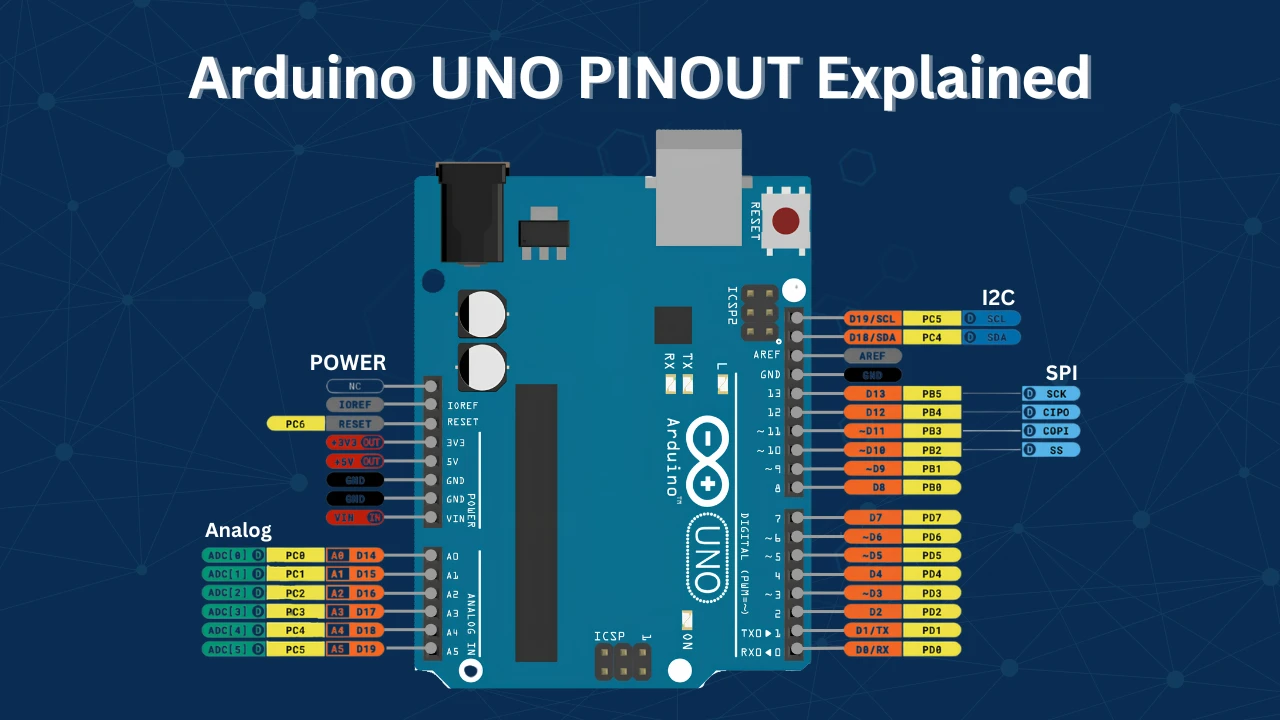
Interrupt Pins by Board
| Board | Interrupt Pins | Notes |
|---|---|---|
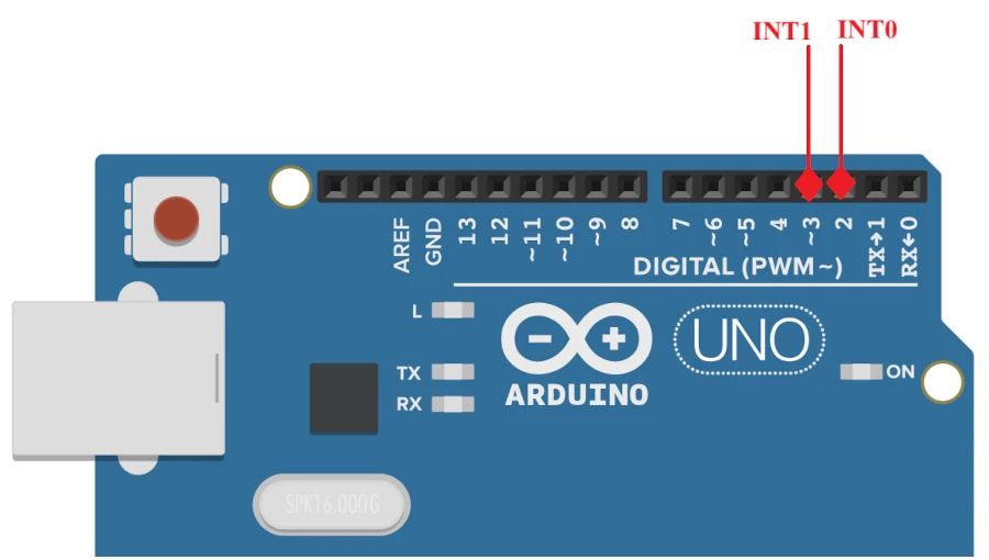
| UNO / Nano / Pro Mini | 2, 3 | INT0 = pin 2, INT1 = pin 3 |
| Mega 2560 | 2, 3, 18, 19, 20, 21 | 6 external interrupts |
| Leonardo / Micro | 0, 1, 2, 3, 7 | 5 external interrupts |
| Due | All digital pins | SAMD21 supports all pins |
| ESP32 | Almost all pins | Via GPIO matrix |
To confirm which pins support interrupts on your board, use digitalPinToInterrupt(). It returns the interrupt number if the pin is valid, or -1 if not:
void setup() {
Serial.begin(9600);
delay(2000);
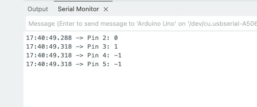
Serial.print("Pin 2: "); Serial.println(digitalPinToInterrupt(2)); // 0 on UNO
Serial.print("Pin 3: "); Serial.println(digitalPinToInterrupt(3)); // 1 on UNO
Serial.print("Pin 4: "); Serial.println(digitalPinToInterrupt(4)); // -1 (not valid)
Serial.print("Pin 5: "); Serial.println(digitalPinToInterrupt(5)); // -1 (not valid)
}
void loop() {}
The image below shows the output of the code on the serial monitor.
Always use digitalPinToInterrupt(pin) inside attachInterrupt(), never hardcode the interrupt number directly. Interrupt numbers differ across boards. The function digitalPinToInterrupt() handles this automatically.
attachInterrupt() and Trigger Modes
Syntax
attachInterrupt(digitalPinToInterrupt(pin), ISR_function, mode);pin— the interrupt-capable pin numberISR_function— the function to run when the interrupt fires (no parameters, returns void)mode— the signal condition that triggers the interrupt
To disable an interrupt:
detachInterrupt(digitalPinToInterrupt(pin));After detachInterrupt(), the pin returns to a regular input. Re-enable it any time with attachInterrupt().
Trigger Modes
| Mode | Triggers When | Typical Use |
|---|---|---|
RISING | Pin goes LOW → HIGH | Button release, pulse start |
FALLING | Pin goes HIGH → LOW | Button press (with INPUT_PULLUP) |
CHANGE | Pin changes in either direction | Rotary encoders, pulse counting |
LOW | Pin is continuously LOW | Level-triggered, less common |
FALLING is the most common choice for buttons with INPUT_PULLUP. The pin remains at HIGH and goes LOW when pressed.
CHANGE doubles the resolution of rotary encoders by catching both edges of each pulse.
LOW fires continuously while the pin is held low, not just on the transition — use it with care to avoid an interrupt loop.
Configuring the Pin — INPUT vs INPUT_PULLUP
Before attaching an interrupt, you must configure the pin as an input. This tells the Arduino that the pin will receive a signal from an external device, like a button or sensor.
You can set a pin as:
INPUT— for reading an external signal with your own pull-up or pull-down resistor.INPUT_PULLUP— enables Arduino’s internal pull-up resistor, keeping the pin HIGH by default and detecting a LOW signal when pressed.
Example:
pinMode(2, INPUT_PULLUP); // Configure pin 2 as input with internal pull-upUsing INPUT_PULLUP is convenient because you don’t need an external resistor. The pin is automatically pulled to the VDD, hence it also avoids the risk of damaging the MCU with High Voltage input.
detachInterrupt() — Disable an Interrupt
Sometimes, you may want to temporarily disable an interrupt, for example, during a critical section of your program or to avoid false triggers. To stop an interrupt from responding, use the detachInterrupt() function.
detachInterrupt(digitalPinToInterrupt(pin));Example:
detachInterrupt(digitalPinToInterrupt(2)); // Disable interrupt on pin 2After calling this function, the interrupt will no longer trigger until you re-enable it with attachInterrupt() again. This feature is handy when handling noisy inputs or when you need more control over timing-sensitive tasks.
Button Toggle LED Example
This example uses a push button on pin 2 to toggle an LED on pin 13. The ISR sets a flag. The main loop reads the flag, debounces, and toggles the LED. This is the correct pattern for interrupt-driven input handling.
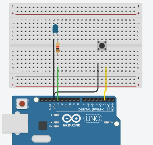
Wiring
- Button: one leg to pin 2, other leg to GND.
INPUT_PULLUPkeeps the pin HIGH by default — pressing the button pulls it LOW. - LED: anode to pin 13 via a 220 Ω resistor, cathode to GND. The UNO’s built-in LED is already on pin 13.
Code
const int buttonPin = 2;   // INT0 — external interrupt pin
const int ledPin    = 13;  // LED output pin

volatile bool irqFlag = false;      // set inside ISR, read in loop()
unsigned long lastToggle  = 0;
const unsigned long debounceMs = 50;

void setup() {
  pinMode(ledPin,    OUTPUT);
  pinMode(buttonPin, INPUT_PULLUP);

  attachInterrupt(digitalPinToInterrupt(buttonPin), handleButtonISR, FALLING);

  Serial.begin(9600);
  Serial.println("Ready — press the button.");
}

void loop() {
  if (irqFlag) {
    irqFlag = false;

    unsigned long now = millis();
    if (now - lastToggle >= debounceMs) {
      digitalWrite(ledPin, !digitalRead(ledPin));  // toggle LED
      lastToggle = now;
    }
  }
}

// ISR — keep it short. Only set the flag.
void handleButtonISR() {
  irqFlag = true;
}volatile bool irqFlag is the bridge between the ISR and loop(). The ISR only sets it to true — no logic, no Serial, no delay. The main loop checks it on every iteration, clears it, and then does the actual work: debouncing and toggling the LED.
The debounce check compares the current millis() against lastToggle. If less than 50 ms has passed since the last toggle, the press is ignored — this filters out the multiple rapid transitions a mechanical button generates when physically pressed.
Result
The GIF below shows the simulation for this project on the TinkerCAD simulator.
Each button press fires one interrupt, sets the flag, and the LED changes state exactly once. The debounce logic ensures a single press never produces multiple toggles.
ISR Rules and Troubleshooting
ISR Rules
Keep ISRs short. The ISR interrupts everything — including other time-sensitive code. A long ISR delays both the main program and any other pending interrupts.
Never use delay() inside an ISR. delay() depends on timer interrupts to count time. Since interrupts are disabled during an ISR, delay() will hang indefinitely.
Never use Serial.print() inside an ISR. Serial transmission uses interrupts internally. Calling it from an ISR causes unpredictable behaviour and potential lock-ups.
Declare shared variables as volatile. Without volatile, the compiler may cache the variable in a register and never re-read it from memory. volatile forces a fresh memory read on every access, ensuring the main loop sees the value the ISR wrote.
volatile bool irqFlag = false;    // correct
volatile int pulseCount = 0; // correct for counters tooDisable interrupts when reading multi-byte volatile variables in loop(). A 16-bit or 32-bit variable can be read mid-update by the main loop if the ISR modifies it between reads. Use noInterrupts() / interrupts() to guard the read:
noInterrupts();
unsigned long count = pulseCount;  // atomic copy
interrupts();Button Bounce and False Triggers
A mechanical button does not produce a clean transition. When pressed, the contacts bounce for 1–10 ms, generating dozens of rapid HIGH/LOW transitions. Each transition fires a new interrupt, causing multiple ISR calls from a single press.
The software debounce in the example above handles this. For hardware debounce, add a 100 nF capacitor across the button contacts (one leg to pin, one leg to GND). The capacitor absorbs the bounce transients before they reach the pin.
LED Toggles Multiple Times per Press
The debounce window is too short. Increase debounceMs from 50 to 100. If it still triggers multiple times, add a hardware capacitor.
Interrupt Never Fires
- Check that you are using an interrupt-capable pin. Run the
digitalPinToInterrupt()checker above — it must not return-1. - Confirm
pinMode()is called beforeattachInterrupt(). - Check the trigger mode matches the signal. With
INPUT_PULLUPand a button to GND, useFALLING.
millis() Drifts or Freezes
You are calling delay() or blocking code inside the ISR. Remove it. millis() is driven by Timer0’s overflow interrupt — if your ISR runs too long or disables interrupts, Timer0 does not update.
Using Interrupts vs Polling
Use interrupts when you need to catch brief signals (under 1 ms), count pulses from encoders or sensors, or respond to events while the main loop is busy with other work.
Use polling when the signal changes slowly (buttons pressed for 100+ ms), you already have a tight loop that checks inputs frequently, or the added complexity of ISR flag management is not justified.
Arduino External Interrupts FAQ
Conclusion
External interrupts are the most fundamental upgrade you can make to how Arduino responds to the physical world. Polling burns CPU cycles checking states that may not have changed. Interrupts let the hardware do that work — the moment the signal changes, the ISR fires, the flag is set, and your main loop handles it in the next cycle without missing anything.
In this tutorial you covered the complete picture: how the ATmega328P hardware interrupt controller works, which pins carry INT0 and INT1 on Uno/Nano versus the expanded sets on Mega and Leonardo, how to configure attachInterrupt() with all four trigger modes, how to write a correct ISR using the volatile flag pattern that keeps the handler to a single line, and how to add millis()-based debounce in the main loop to handle the mechanical noise of a real push button.
From here, interrupts feed naturally into more advanced concurrency. The Arduino FreeRTOS Interrupts tutorial shows how to signal RTOS tasks from an ISR using binary semaphores — the same flag pattern you used here, but with proper task scheduling behind it. The IR Sensor counter and PIR motion detector tutorials both use interrupt-driven pulse counting in practice. Download the full project above and explore the Arduino Core tutorials for the next step.
Download Arduino External Interrupt Project Files
Complete Arduino project with digitalPinToInterrupt() pin checker sketch and full LED toggle example using attachInterrupt() on INT0 (pin 2), volatile flag ISR pattern, and millis()-based debounce. No external libraries required. Compatible with Uno, Nano, Mega, and Leonardo (check board interrupt pin map). Free to download — support the work if it helped you.
Browse More Arduino Core Tutorials
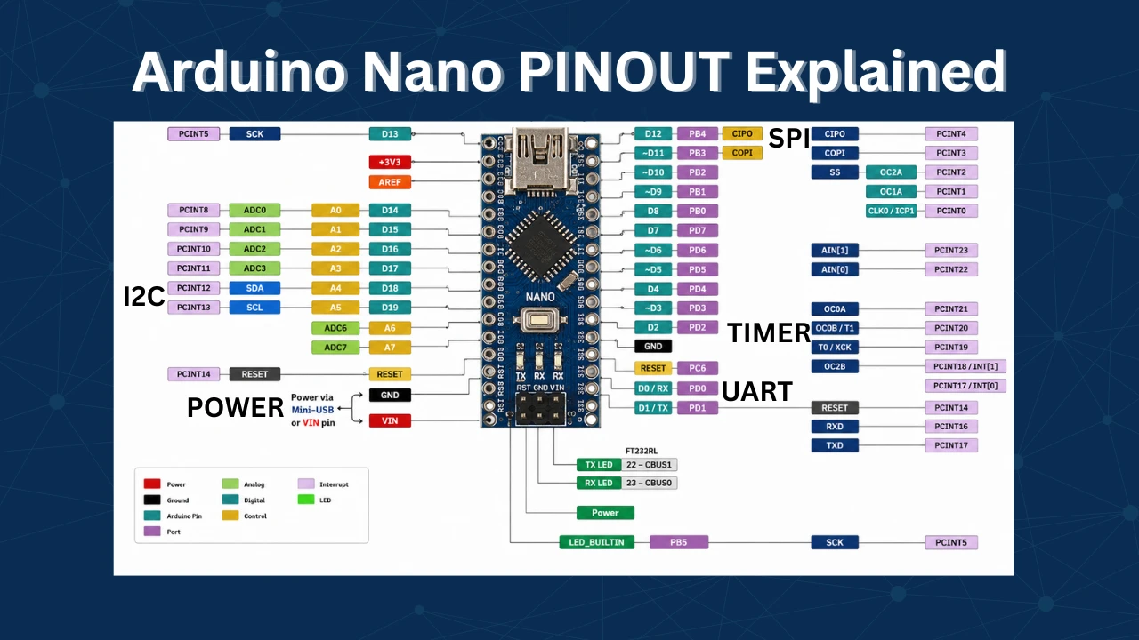
Arduino Nano Pinout – Complete Guide with Diagram
Arduino digitalWrite() and digitalRead(): Complete Guide with Examples
Arduino UART Tutorial: Serial Communication, Send, Receive & LED Control
Arduino ADC and analogRead() Explained: Complete Guide with Examples

Arduino I2C Tutorial: Wire Library, Master/Slave, Scanner & Troubleshooting

Subscribe
Login
0 Comments
Newest
