
Home ▸ Arduino ▸ Displays & Interfaces ▸
Updated On: May 4, 2026
Arduino ILI9341 Touchscreen Tutorial: XPT2046 Wiring, Graphics, Calibration & UI
The ILI9341 is a 2.4/2.8-inch color TFT display with 240×320 resolution and 65K colors — one of the most capable displays you can add to an Arduino project. When combined with the XPT2046 resistive touch controller that ships on most ILI9341 modules, you get a full touchscreen interface: buttons, menus, color pickers, and multi-page apps, all controlled by finger input.
In this tutorial you’ll learn how to wire the ILI9341 and XPT2046 to an Arduino Uno over SPI with proper 5V-to-3.3V level shifting, install Adafruit ILI9341, Adafruit GFX, and XPT2046 Touchscreen libraries, draw text and shapes, display a bitmap icon from PROGMEM, read raw touch coordinates, calibrate the touch panel to map accurately to screen pixels, build touch-responsive buttons with visual feedback, create a mini LED control panel, and implement a multi-page UI with Home, Settings, and Info pages. Every section includes a complete working sketch. The project files are available to download at the bottom of the page.
This is part of the Arduino Display Tutorials series. For smaller displays without touch, see ST7735 Arduino TFT tutorial (1.8-inch SPI color display) and SH1106 OLED tutorial (1.3-inch I2C monochrome). For displays using U8g2, the ST7920 series covers graphics, animations, and dashboard UI across four parts. For character displays, LCD1602 I2C with Arduino is a simpler starting point. If you plan to build an MP3 player with the ILI9341, see the Arduino MP3 Music Player tutorial which uses the same display.
Table Of Contents
- What is the ILI9341 TFT Display with XPT2046 Touch?
- ILI9341 + XPT2046 Wiring & Library Setup for Arduino
- Arduino ILI9341 Examples: Graphics, Bitmaps & Touch
- Displaying Bitmap Images on ILI9341
- Building a Touchscreen UI with ILI9341 + XPT2046
- ILI9341 + XPT2046 Troubleshooting & Common Issues
- Arduino ILI9341 Touchscreen: Frequently Asked Questions
What is the ILI9341 TFT Display with XPT2046 Touch?
In this part, we will understand the basic features of the ILI9341 TFT display. This helps you know what you can do with it and why it is widely used in Arduino projects. The display is simple to connect, fast to update, and supports rich graphics. Once you know its features, it becomes easier to follow the rest of the tutorial.
ILI9341 Specifications: Resolution, Colors and SPI Interface
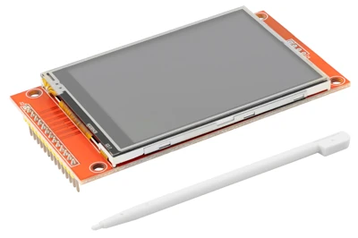
The ILI9341 is a 2.4-inch or 2.8-inch TFT LCD module that supports a 240×320 pixel resolution. This is more than enough to show clear text, smooth shapes, icons, menus, and small images. The display uses a 16-bit color format (65K colors), which gives bright and sharp visuals.
Most Arduino users connect the ILI9341 using SPI mode, because SPI needs fewer pins and works well on boards like Arduino UNO, Nano, and Mega. The driver chip works internally with commands, so the library takes care of drawing the pixels. This makes the display responsive, even with basic microcontrollers.
Some common pin names you will see are CS, DC, RESET, MOSI, MISO, SCK, and LED. These pins handle communication, data selection, and backlight control.
Overall, the display gives you a smooth, colorful output with very simple wiring.
Why ILI9341 is Popular for Arduino Projects
The ILI9341 is popular because it offers a great balance of features, performance, and price. It is cheap, easy to find, and works well even with low-power boards. The Adafruit and community libraries make drawing graphics very simple. You can show text, shapes, images, and charts using just a few lines of code.
Another reason for its popularity is the support for touch screens. Many ILI9341 modules come with a resistive touchscreen that uses the XPT2046 controller. This lets you add touch buttons and interactive menus without extra hardware.
The display is also very stable. It works smoothly in DIY electronics, hobby robots, IoT dashboards, weather stations, home automation panels, and even small games.
ILI9341 + XPT2046 Wiring & Library Setup for Arduino
Before writing code, we must wire the display and touch controller the right way. These connections are simple once you understand what each pin does. Proper wiring ensures stable graphics output and accurate touch readings. Let’s go through the connections step by step.
Wiring ILI9341 to Arduino UNO via SPI
The ILI9341 display works very well in SPI mode on Arduino boards such as the UNO, Nano, and Mega. SPI requires fewer wires and delivers faster screen updates compared to parallel mode.
| ILI9341 Pin | Arduino UNO | Function |
|---|---|---|
| VCC / 5V | 5V | Power for display |
| GND | GND | Ground |
| CS | 10 | Chip Select for display |
| DC / RS | 9 | Data/Command selection |
| RESET / RST | 8 | Reset pin (optional) |
| MOSI | 11 | SPI data output |
| MISO | 12 | SPI data input |
| SCK / CLK | 13 | SPI clock |
| LED | 3.3V or 5V | Backlight |
Arduino UNO SPI pins (11, 12, 13) cannot be changed, as they are hardware SPI. The remaining pins (CS, DC, RESET) can be connected to any free digital pin.
You can tie RESET to 3.3V for fewer wires, but using a pin generally improves stability.
5V to 3.3V Level Shifting for ILI9341 Signals
Most Arduino boards (UNO, Nano, Mega) use 5V logic on their digital pins. However, the ILI9341 display accepts only 3.3V signals.
This means:
- MOSI (11), SCK (13), CS, DC, RESET pins must be level-shifted to 3.3V
- Only MISO is safe, because it is output from the display (3.3V to 5V input)
If you check the connection guide on the display module, you will often find a recommended resistor divider network to reduce 5V signals down to 3.3V.
Example (common wiring method):
- Use a 2-resistor voltage divider (e.g., 1k + 2k) on these lines:
- MOSI
- SCK
- CS
- DC
- RESET
The image below shows the wiring connection between ILI9341 display and Arduino.
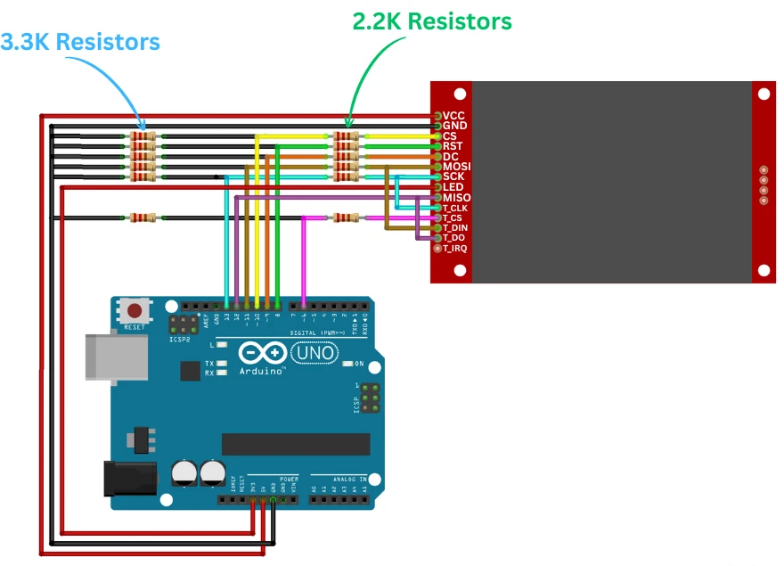
You can also use a proper logic level shifter, which provides cleaner, more reliable signals.
Wiring the XPT2046 Touch Controller to Arduino
The touchscreen controller (XPT2046) also uses SPI, but both devices can share the same SPI bus. You only need a separate Chip Select (CS) for the touch controller.
The table below explains the connection between XPT2046 and Arduino.
| XPT2046 Pin | Arduino UNO | Function |
|---|---|---|
| T_IRQ | Not Used | Touch interrupt (optional) |
| T_D0 / MISO | 12 | SPI MISO (shared) |
| T_DIN / MOSI | 11 | SPI MOSI (shared) |
| T_CS | 6 | Touch chip select |
| T_CLK | 13 | SPI clock (shared) |
Just like the ILI9341, the touch controller works at 3.3V only.
If your module does not include onboard level shifting, apply the same resistor divider or level shifter on:
- MOSI
- SCK
- T_CS
MISO is safe, as it outputs 3.3V.
Power Requirements and Recommended CS Pins
The ILI9341 and XPT2046 work best when powered correctly:
- ILI9341 VCC -> 5V (Most modules have onboard 3.3V regulators)
- XPT2046 VCC -> 3.3V (Touch controller is sensitive to voltage)
- LED pin -> 3.3V or 5V, depending on your TFT module
For stable operation:
- Use short wires to reduce flicker or noise.
- Avoid powering from USB if the backlight draws high current; use an external 5V supply if needed.
- Keep CS pins separate:
- TFT_CS = 10
- TOUCH_CS = 6
This setup keeps SPI reliable and prevents the display and touch controller from interfering with each other.
Installing Adafruit GFX, ILI9341 and XPT2046 Libraries
To use the display easily, we need a few well-known libraries. These libraries handle all the low-level graphics and touch functions, so we don’t have to deal with complex commands. Once the libraries are installed, working with the ILI9341 display and XPT2046 touch controller becomes very simple.
Install Adafruit_GFX and Adafruit_ILI9341
The Adafruit_GFX library is the core graphics engine. It provides functions to draw text, lines, shapes, and bitmaps. The Adafruit_ILI9341 library adds support for the ILI9341 driver and makes it easy to draw on the TFT display.
To install them:
- Open Arduino IDE
- Go to Sketch → Include Library → Manage Libraries
- In the search bar, type Adafruit GFX
- Install Adafruit GFX Library
- Search for Adafruit ILI9341
- Install Adafruit ILI9341
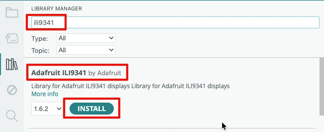
After installation, you get access to simple functions like:
fillScreen()drawPixel()setCursor()setTextColor()drawRect(),drawCircle(), and more
Install XPT2046_Touchscreen Library
The XPT2046 library helps us read touch input. It provides functions to detect touches and get X, Y coordinates.
To install:
- Open Library Manager
- Search for XPT2046_Touchscreen
- Install the library by Paul Stoffregen

This library supports:
- Checking whether the screen is touched:
touch.touched() - Getting touch coordinates:
touch.getPoint() - Handling pressure values
It works perfectly with SPI and can share the same MOSI, MISO, and SCK lines as the display.
Optional Libraries for Faster Drawing
If you want faster performance, you can install a few optional libraries. These are helpful when you build heavier UIs or draw many elements on the screen.
Popular options include:
- ILI9341_due – Faster graphics functions
- TFT_eSPI – Very fast library (mainly for ESP32 and ESP8266)
- SPIFFS or LittleFS image helpers – For loading images efficiently
For Arduino UNO/Nano users, the standard Adafruit libraries are good enough. But if you move to a faster board later, these libraries can speed up heavy drawing tasks.
Arduino ILI9341 Examples: Graphics, Bitmaps & Touch
Now we will write our first program to test the TFT display. This simple test confirms that your wiring is correct and the display is responding properly. We will draw text, lines, and basic shapes to make sure everything works.
Drawing Text and Shapes on ILI9341
#include <Adafruit_GFX.h>
#include <Adafruit_ILI9341.h>

// Pin definitions
#define TFT_CS   10
#define TFT_DC    9
#define TFT_RST   8   // You can also connect this to 3.3V

// Create display object
Adafruit_ILI9341 tft = Adafruit_ILI9341(TFT_CS, TFT_DC, TFT_RST);

void setup() {
  tft.begin();                 // Start the display
  tft.setRotation (1);
  tft.fillScreen(ILI9341_BLACK); // Clear screen

  // Draw a welcome message
  tft.setCursor(20, 20);
  tft.setTextSize(2);
  tft.setTextColor(ILI9341_YELLOW);
  tft.println("ILI9341 Test");

  // Draw a red line
  tft.drawLine(10, 60, 230, 60, ILI9341_RED);

  // Draw a green rectangle
  tft.drawRect(10, 80, 100, 50, ILI9341_GREEN);

  // Filled blue rectangle
  tft.fillRect(120, 80, 100, 50, ILI9341_BLUE);

  // Draw a circle
  tft.drawCircle(60, 180, 30, ILI9341_CYAN);

  // Filled circle
  tft.fillCircle(180, 180, 30, ILI9341_MAGENTA);
}

void loop() {
  // Nothing here for now
}Explanation
We begin by including Adafruit_GFX and Adafruit_ILI9341, the two libraries needed for drawing shapes and text. We then create the display object using the CS, DC, and RESET pins.
tft.begin()starts communication with the display.tft.fillScreen()clears the display and sets a background color.setCursor(),setTextSize(), andsetTextColor()prepare the screen to print text.println()writes text on the display.drawLine(),drawRect(),fillRect(),drawCircle(), andfillCircle()are basic drawing functions from the Adafruit_GFX library.
These commands are the building blocks for all graphics. You will use them often in the next demos.
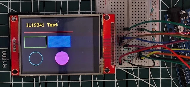
Output
The image below shows the display printing text and drawing simple shapes like lines, rectangles, and circles. This confirms that the display is wired correctly and fully functional.
Displaying Bitmap Images on ILI9341
The ILI9341 can show beautiful images. In this demo, we will load small bitmaps to create simple graphics. Bitmaps are ideal for icons, logos, UI elements, and splash screens. The Adafruit library makes drawing bitmaps very easy once the image is converted into the right format.
Below is a sample code that displays a simple 16×16 bitmap icon on the ILI9341 screen.
#include <Adafruit_GFX.h>
#include <Adafruit_ILI9341.h>

#define TFT_CS   10
#define TFT_DC    9
#define TFT_RST   8

Adafruit_ILI9341 tft = Adafruit_ILI9341(TFT_CS, TFT_DC, TFT_RST);

const unsigned char smiley1 [] PROGMEM = {
	0xff, 0xff, 0xff, 0xff, 0xff, 0xff, 0xff, 0xff, 0xff, 0xff, 0xff, 0xff, 0xff, 0xff, 0xff, 0xff,
	0xff, 0xff, 0xff, 0x80, 0x00, 0xff, 0xff, 0xff, 0xff, 0xff, 0xf8, 0x00, 0x00, 0x1f, 0xff, 0xff,
	0xff, 0xff, 0xe0, 0x0f, 0xf8, 0x07, 0xff, 0xff, 0xff, 0xff, 0x80, 0xff, 0xff, 0x81, 0xff, 0xff,
	0xff, 0xff, 0x07, 0xff, 0xff, 0xe0, 0x7f, 0xff, 0xff, 0xfc, 0x1f, 0xff, 0xff, 0xfc, 0x3f, 0xff,
	0xff, 0xf8, 0x7f, 0xff, 0xff, 0xfe, 0x0f, 0xff, 0xff, 0xf0, 0xff, 0xff, 0xff, 0xff, 0x87, 0xff,
	0xff, 0xe1, 0xff, 0xff, 0xff, 0xff, 0xc3, 0xff, 0xff, 0xc7, 0xff, 0xff, 0xff, 0xff, 0xe1, 0xff,
	0xff, 0x8f, 0xff, 0xff, 0xff, 0xff, 0xf0, 0xff, 0xff, 0x1f, 0xff, 0xff, 0xff, 0xff, 0xf8, 0x7f,
	0xfe, 0x3f, 0xff, 0xff, 0xff, 0xff, 0xfc, 0x7f, 0xfc, 0x3f, 0xff, 0xff, 0xff, 0xff, 0xfe, 0x3f,
	0xfc, 0x7f, 0xff, 0xff, 0xff, 0xff, 0xff, 0x1f, 0xf8, 0xff, 0xff, 0xff, 0xff, 0xff, 0xff, 0x1f,
	0xf8, 0xff, 0xff, 0xff, 0xff, 0xff, 0xff, 0x8f, 0xf1, 0xff, 0xff, 0xff, 0xff, 0xff, 0xff, 0x8f,
	0xf1, 0xff, 0xf0, 0xff, 0xff, 0x8f, 0xff, 0xc7, 0xe3, 0xff, 0xe0, 0x7f, 0xff, 0x07, 0xff, 0xc7,
	0xe3, 0xff, 0xe0, 0x7f, 0xfe, 0x03, 0xff, 0xe3, 0xe7, 0xff, 0xc0, 0x3f, 0xfe, 0x03, 0xff, 0xe3,
	0xc7, 0xff, 0xc0, 0x3f, 0xfe, 0x03, 0xff, 0xe3, 0xc7, 0xff, 0xc0, 0x3f, 0xfe, 0x03, 0xff, 0xf3,
	0xc7, 0xff, 0xc0, 0x3f, 0xfe, 0x03, 0xff, 0xf1, 0xcf, 0xff, 0xc0, 0x3f, 0xfe, 0x03, 0xff, 0xf1,
	0xcf, 0xff, 0xc0, 0x3f, 0xfe, 0x03, 0xff, 0xf1, 0xcf, 0xff, 0xe0, 0x7f, 0xfe, 0x03, 0xff, 0xf1,
	0x8f, 0xff, 0xe0, 0x7f, 0xfe, 0x03, 0xff, 0xf9, 0x8f, 0xff, 0xf0, 0xff, 0xff, 0x07, 0xff, 0xf9,
	0x8f, 0xff, 0xf9, 0xff, 0xff, 0x8f, 0xff, 0xf9, 0x8f, 0xff, 0xff, 0xff, 0xff, 0xff, 0xff, 0xf9,
	0x8f, 0xff, 0xff, 0xff, 0xff, 0xff, 0xff, 0xf9, 0xcf, 0xff, 0xff, 0xff, 0xff, 0xff, 0xff, 0xf1,
	0xcf, 0xff, 0xff, 0xff, 0xff, 0xff, 0xff, 0xf1, 0xcf, 0xff, 0xff, 0xff, 0xff, 0xff, 0xff, 0xf1,
	0xc7, 0xff, 0xff, 0xff, 0xff, 0xff, 0xff, 0xf1, 0xc7, 0xfc, 0x7f, 0xff, 0xff, 0xff, 0x3f, 0xf3,
	0xc7, 0xfc, 0x7f, 0xff, 0xff, 0xfe, 0x3f, 0xe3, 0xe7, 0xfe, 0x3f, 0xff, 0xff, 0xfc, 0x3f, 0xe3,
	0xe3, 0xfe, 0x1f, 0xff, 0xff, 0xf8, 0x7f, 0xe3, 0xe3, 0xff, 0x0f, 0xff, 0xff, 0xf0, 0xff, 0xc7,
	0xf1, 0xff, 0x87, 0xff, 0xff, 0xe1, 0xff, 0xc7, 0xf1, 0xff, 0xc1, 0xff, 0xff, 0xc3, 0xff, 0x8f,
	0xf8, 0xff, 0xe0, 0x7f, 0xff, 0x07, 0xff, 0x8f, 0xf8, 0xff, 0xf8, 0x0f, 0xf8, 0x0f, 0xff, 0x1f,
	0xfc, 0x7f, 0xfe, 0x00, 0x00, 0x3f, 0xff, 0x1f, 0xfc, 0x3f, 0xff, 0x80, 0x00, 0xff, 0xfe, 0x3f,
	0xfe, 0x3f, 0xff, 0xf8, 0x0f, 0xff, 0xfc, 0x7f, 0xff, 0x1f, 0xff, 0xff, 0xff, 0xff, 0xf8, 0x7f,
	0xff, 0x8f, 0xff, 0xff, 0xff, 0xff, 0xf0, 0xff, 0xff, 0xc7, 0xff, 0xff, 0xff, 0xff, 0xe1, 0xff,
	0xff, 0xe1, 0xff, 0xff, 0xff, 0xff, 0xc3, 0xff, 0xff, 0xf0, 0xff, 0xff, 0xff, 0xff, 0x87, 0xff,
	0xff, 0xf8, 0x7f, 0xff, 0xff, 0xfe, 0x0f, 0xff, 0xff, 0xfc, 0x1f, 0xff, 0xff, 0xf8, 0x3f, 0xff,
	0xff, 0xff, 0x07, 0xff, 0xff, 0xe0, 0x7f, 0xff, 0xff, 0xff, 0x80, 0xff, 0xff, 0x81, 0xff, 0xff,
	0xff, 0xff, 0xe0, 0x0f, 0xf0, 0x07, 0xff, 0xff, 0xff, 0xff, 0xfc, 0x00, 0x00, 0x1f, 0xff, 0xff,
	0xff, 0xff, 0xff, 0x80, 0x00, 0xff, 0xff, 0xff, 0xff, 0xff, 0xff, 0xff, 0xff, 0xff, 0xff, 0xff
};

void setup() {
  tft.begin();
  tft.fillScreen(ILI9341_BLACK);
  tft.setRotation(1);

  // Draw title
  tft.setCursor(10, 10);
  tft.setTextSize(2);
  tft.setTextColor(ILI9341_YELLOW);
  tft.println("Bitmap Demo");

  // Draw bitmap on screen
  tft.drawBitmap(40, 40, smiley1, 64, 64, ILI9341_PINK);
}

void loop() {
}Explanation
The code starts by initializing the ILI9341 display. We prepare a small 64×64 pixel bitmap stored in program memory using PROGMEM. This saves valuable RAM on Arduino boards like UNO and Nano.
The key function here is:
tft.drawBitmap(x, y, bitmapArray, width, height, color);x, y-> Starting position on the screenbitmapArray-> The bitmap stored in PROGMEMwidth, height-> Size of the bitmapcolor-> Color to draw the bitmap
This format works for monochrome bitmaps. If you want colorful images, you must convert them into RGB565 format and use drawRGBBitmap(). Both methods work well for icons and small images.
This demo confirms that bitmap drawing works correctly and prepares you for upcoming UI elements.
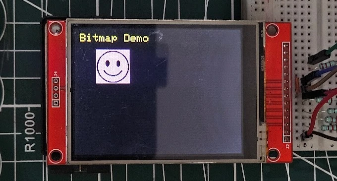
Output
The image below shows the ILI9341 drawing the bitmap icon on the display. You will see the smiley image appear clearly, showing that the bitmap loading is working as expected.
Reading Raw Touch Coordinates with XPT2046
Next, we explore touch input. The XPT2046 touch controller reads finger touches and gives us X and Y coordinates. This makes your display interactive. You can detect taps, create buttons, sliders, and even simple games. In this section, we will read raw touch values to understand how the touch panel behaves.
#include <Adafruit_GFX.h>
#include <Adafruit_ILI9341.h>
#include <XPT2046_Touchscreen.h>

#define TFT_CS   10
#define TFT_DC    9
#define TFT_RST   8

#define TOUCH_CS  6

Adafruit_ILI9341 tft = Adafruit_ILI9341(TFT_CS, TFT_DC, TFT_RST);
XPT2046_Touchscreen touch(TOUCH_CS);

void setup() {
  Serial.begin(9600);

  tft.begin();
  tft.fillScreen(ILI9341_BLACK);
  tft.setRotation(2);

  touch.begin();
  touch.setRotation(0);   // Match display rotation

  tft.setTextSize(2);
  tft.setTextColor(ILI9341_GREEN);
  tft.setCursor(10, 10);
  tft.println("Touch Test");
}

void loop() {
  if (touch.touched()) {
    TS_Point p = touch.getPoint();  // Get raw touch point

    Serial.print("X = ");
    Serial.print(p.x);
    Serial.print("  Y = ");
    Serial.println(p.y);

    // Draw a dot where touched (not calibrated yet)
    int x = map(p.x, 200, 3800, 0, 240);
    int y = map(p.y, 200, 3800, 0, 320);

    tft.fillCircle(x, y, 3, ILI9341_YELLOW);
  }
  delay(5);
}Explanation
We begin by including all required libraries:
- Adafruit_GFX and Adafruit_ILI9341 for graphics
- XPT2046_Touchscreen for reading touch input
Next, we define the touch CS pin. The display and touch share the same SPI pins, but each has its own CS line. We will not use the IRQ pin, so it is not defined here.
touch.begin() starts the touch controller, and touch.setRotation() makes the touch orientation match the display. You can try different rotations (0-3) to align the touch axis with the display.
Inside the loop:
touch.touched()checks if the screen is being touched.touch.getPoint()returns a raw TS_Point containingp.x,p.y, and pressure.- Raw touch values are mapped to the display size using
map(). - A small yellow dot is drawn at the touched location.
This demo shows the basic touch behavior before calibration.
Note:
A small delay (5ms) is required for the display and touch to work together. They both share the same SPI bus, hence one need to release the bus for the other to use it. If the delay is not provided, either the display or touch will hold the SPI bus, making only one of them to work.
Output
The video below shows raw touch points appearing on the display as you tap different positions. You will also see X and Y values printed in the Serial Monitor. This confirms that the touch controller is connected and working correctly.
Touch Calibration: Mapping Raw Values to Screen Pixels
Raw touch values are not perfect. They usually come with noise and offset errors. To get accurate touch positions, we need a simple calibration method. Calibration helps map the raw X and Y values to the actual screen coordinates so your buttons and UI respond correctly.
This calibration example asks the user to touch the four corners of the screen. It records the minimum and maximum raw values and uses them to map accurate coordinates.
#include <Adafruit_GFX.h>
#include <Adafruit_ILI9341.h>
#include <XPT2046_Touchscreen.h>

#define TFT_CS   10
#define TFT_DC    9
#define TFT_RST   8

#define TOUCH_CS  6

Adafruit_ILI9341 tft = Adafruit_ILI9341(TFT_CS, TFT_DC, TFT_RST);
XPT2046_Touchscreen touch(TOUCH_CS);

int xMinVal, xMaxVal, yMinVal, yMaxVal;

TS_Point waitForTouch() {
  while (!touch.touched())
  {
    delay(5);
  }
  delay(200);
  TS_Point p = touch.getPoint();
  while (touch.touched());
  delay(200);
  return p;
}

void setup() {
  Serial.begin(9600);
  tft.begin();
  tft.setRotation(2);

  touch.begin();
  touch.setRotation(0);

  tft.fillScreen(ILI9341_BLACK);
  tft.setTextSize(2);
  tft.setTextColor(ILI9341_WHITE);

  // Ask user to touch four corners
  tft.fillScreen(ILI9341_BLACK);
  tft.setCursor(20, 140);
  tft.println("Touch TOP-LEFT");
  TS_Point p1 = waitForTouch();
  xMinVal = p1.x;
  yMinVal = p1.y;

  tft.fillScreen(ILI9341_BLACK);
  tft.setCursor(20, 140);
  tft.println("Touch TOP-RIGHT");
  TS_Point p2 = waitForTouch();
  xMaxVal = p2.x;

  tft.fillScreen(ILI9341_BLACK);
  tft.setCursor(20, 140);
  tft.println("Touch BOTTOM-LEFT");
  TS_Point p3 = waitForTouch();
  yMaxVal = p3.y;

  tft.fillScreen(ILI9341_BLACK);
  tft.setCursor(20, 140);
  tft.println("Calibration Done!");

  // Print values
  Serial.println("Calibration Values:");
  Serial.print("xMin = "); Serial.println(xMinVal);
  Serial.print("xMax = "); Serial.println(xMaxVal);
  Serial.print("yMin = "); Serial.println(yMinVal);
  Serial.print("yMax = "); Serial.println(yMaxVal);
}

void loop() {
}Explanation
The touch panel gives raw values that do not match the screen size. Most modules produce raw ranges like:
- X: 200 to 3800
- Y: 200 to 3900
But your screen resolution is always:
- Width: 240 pixels
- Height: 320 pixels
To fix this, we use simple mapping:
trueX = map(rawX, xMinVal, xMaxVal, 0, 240);
trueY = map(rawY, yMinVal, yMaxVal, 0, 320);Here’s how the calibration helps:
xMinValandxMaxValdefine the raw limits of the panel horizontally.yMinValandyMaxValdefine the raw limits vertically.map()converts them into valid pixel coordinates.
After calibration, the touch will match the display exactly, which is important for buttons, menus, and UI controls.
Output
The video below shows the calibration steps. You will see the display asking you to touch the corners, followed by the collection of raw values. After this calibration, the touch becomes smooth and accurate across the whole ILI9341 screen.
Building a Touchscreen UI with ILI9341 + XPT2046
Touch Buttons with Color Feedback
Now that the touch interface is fully working, it’s time to create a simple and interactive UI. In this section, we will draw a few buttons on the ILI9341 display and detect touch events when the user presses them.
This small experiment will help you understand how to build menus, on-screen controls, and even complete applications in the future.
#include <Adafruit_GFX.h>
#include <Adafruit_ILI9341.h>
#include <XPT2046_Touchscreen.h>

// --- Pins (use your original pins) ---
#define TFT_CS   10
#define TFT_DC    9
#define TFT_RST   8
#define TOUCH_CS  6

// --- Objects (correct constructors) ---
Adafruit_ILI9341 tft = Adafruit_ILI9341(TFT_CS, TFT_DC, TFT_RST);
XPT2046_Touchscreen touch(TOUCH_CS);   // CS pin for XPT2046

#define MINPRESSURE 10
#define MAXPRESSURE 1000

// --- Replace these with the values you obtained from calibration ---
int xMinVal = 200;  // example: raw top-left X
int xMaxVal = 3900; // example: raw top-right X
int yMinVal = 200;  // example: raw top-left Y
int yMaxVal = 3900; // example: raw bottom-left Y

// Button coordinates (screen coordinates)
#define BTN1_X 40
#define BTN1_Y 80
#define BTN1_W 100
#define BTN1_H 50

#define BTN2_X 180
#define BTN2_Y 80
#define BTN2_W 100
#define BTN2_H 50

// Wait for a touch (debounced) and return raw point
TS_Point waitForTouch() {
  while (!touch.touched()) delay(5);    // wait for touch
  delay(100);                           // settle
  TS_Point p = touch.getPoint();
  while (touch.touched()) delay(5);     // wait for release
  delay(100);
  return p;
}

void drawButtons() {
  tft.fillRect(BTN1_X, BTN1_Y, BTN1_W, BTN1_H, ILI9341_RED);
  tft.setCursor(BTN1_X + 25, BTN1_Y + 18);
  tft.setTextColor(ILI9341_WHITE);
  tft.print("RED");

  tft.fillRect(BTN2_X, BTN2_Y, BTN2_W, BTN2_H, ILI9341_CYAN);
  tft.setCursor(BTN2_X + 25, BTN2_Y + 18);
  tft.setTextColor(ILI9341_BLACK);
  tft.print("CYAN");
}

bool checkButton(int tx, int ty, int bx, int by, int bw, int bh) {
  return (tx >= bx && tx <= (bx + bw) && ty >= by && ty <= (by + bh));
}

void setup() {
  Serial.begin(9600);

  // Initialize display and touch and set matching rotations
  tft.begin();
  tft.setRotation(1);      // change if you use a different rotation

  touch.begin();
  touch.setRotation(3);    // MUST match tft rotation for simple mapping

  tft.fillScreen(ILI9341_BLACK);
  tft.setTextSize(2);
  tft.setTextColor(ILI9341_WHITE);

  // Draw initial UI
  drawButtons();
}

void loop() {
  // read raw touch (non-blocking)
  if (!touch.touched()) {
    delay(10);
    return;
  }

  TS_Point p = touch.getPoint();

  // p.x and p.y are raw touch ADC values (range ~0..4095)
  // Map raw values from calibration to screen coordinates.
  // Replace xMinVal/xMaxVal/yMinVal/yMaxVal with your calibrated numbers.
  int sx = map(p.x, xMinVal, xMaxVal, 0, tft.width());
  int sy = map(p.y, yMinVal, yMaxVal, 0, tft.height());

  // Constrain to screen in case of small overshoot
  sx = constrain(sx, 0, tft.width());
  sy = constrain(sy, 0, tft.height());

  Serial.print("raw: "); Serial.print(p.x); Serial.print(","); Serial.print(p.y);
  Serial.print(" -> screen: "); Serial.print(sx); Serial.print(","); Serial.println(sy);

  // Check buttons and act
  if (checkButton(sx, sy, BTN1_X, BTN1_Y, BTN1_W, BTN1_H)) {
    tft.fillRect(BTN1_X, BTN1_Y, BTN1_W, BTN1_H, ILI9341_GREEN);
  } else if (checkButton(sx, sy, BTN2_X, BTN2_Y, BTN2_W, BTN2_H)) {
    tft.fillRect(BTN2_X, BTN2_Y, BTN2_W, BTN2_H, ILI9341_BLUE);
  }

  // small delay to avoid flooding
  delay(150);
}Explanation
1. Display + Touch Initialized Correctly
Adafruit_ILI9341 tft(TFT_CS, TFT_DC, TFT_RST);
XPT2046_Touchscreen touch(TOUCH_CS);Both devices now use the proper constructors and matching rotations.
2. Calibration Values Convert Raw Touch to Screen Pixels
Raw touch values (0–4095) are mapped using your calibration numbers:
int sx = map(p.x, xMinVal, xMaxVal, 0, tft.width());
int sy = map(p.y, yMinVal, yMaxVal, 0, tft.height());This makes the touch align perfectly with the displayed buttons.
3. UI Buttons Drawn on Screen
tft.fillRect(BTN1_X, BTN1_Y, BTN1_W, BTN1_H, ILI9341_RED);
tft.fillRect(BTN2_X, BTN2_Y, BTN2_W, BTN2_H, ILI9341_CYAN);Two clean, colorful buttons appear immediately.
4. Touch Read + Debounced
TS_Point p = touch.getPoint();Raw ADC values are captured safely without accidental double touches.
5. Touch Position Checked Against Buttons
if (checkButton(sx, sy, BTN1_X, BTN1_Y, BTN1_W, BTN1_H)) …A simple bounding-box check determines which button was pressed.
6. Visual Feedback on Press
tft.fillRect(BTN1_X, BTN1_Y, BTN1_W, BTN1_H, ILI9341_GREEN);The button changes color instantly when touched.
Output
The video below shows the output of the code on the ILI9341 display.
You can see in the video:
- Two colored buttons on the screen
- Touching the first button turning it green
- Touching the second button turning it blue
- A smooth and responsive UI interaction similar to a touchscreen app
Mini LED Control Panel with Status Display
In this project, we will build a small control panel user interface (UI). It will have touch buttons, status text, and simple color feedback. This example will help you understand how to build real menus and settings screens for your projects.
#include <SPI.h>
#include <Adafruit_GFX.h>
#include <Adafruit_ILI9341.h>
#include <XPT2046_Touchscreen.h>

// ------------------- Pins -------------------
#define TFT_CS    10
#define TFT_DC     9
#define TFT_RST    8
#define TOUCH_CS   6

Adafruit_ILI9341 tft(TFT_CS, TFT_DC, TFT_RST);
XPT2046_Touchscreen ts(TOUCH_CS);

#define MINP 200   // minimal pressure

// ------------------- Buttons -------------------
#define BTN_W   160
#define BTN_H    50
#define BTN1_X   40
#define BTN1_Y   80
#define BTN2_X   40
#define BTN2_Y  150

// Draw the two buttons
void drawButtons() {
  tft.fillRoundRect(BTN1_X, BTN1_Y, BTN_W, BTN_H, 8, ILI9341_BLUE);
  tft.setCursor(BTN1_X + 20, BTN1_Y + 15);
  tft.setTextColor(ILI9341_WHITE);
  tft.setTextSize(2);
  tft.print("LED ON");

  tft.fillRoundRect(BTN2_X, BTN2_Y, BTN_W, BTN_H, 8, ILI9341_RED);
  tft.setCursor(BTN2_X + 20, BTN2_Y + 15);
  tft.setTextColor(ILI9341_WHITE);
  tft.setTextSize(2);
  tft.print("LED OFF");
}

void setup() {
  pinMode(5, OUTPUT);
  tft.begin();
  ts.begin();

  tft.setRotation(1);
  ts.setRotation(3);

  tft.fillScreen(ILI9341_BLACK);

  tft.setCursor(10, 10);
  tft.setTextColor(ILI9341_YELLOW);
  tft.setTextSize(2);
  tft.print("Control Panel");

  drawButtons();
}

void loop() {
  if (!ts.touched()){
    delay(10);
    return;
  }

  TS_Point p = ts.getPoint();
  if (p.z < MINP) return;

  // Convert raw touch → screen coords
  int x = map(p.x, 200, 3800, 0, 320);
  int y = map(p.y, 200, 3800, 0, 240);

  // LED ON button
  if (x > BTN1_X && x < BTN1_X + BTN_W &&
      y > BTN1_Y && y < BTN1_Y + BTN_H) {

    digitalWrite(5, HIGH);

    tft.fillRect(0, 200, 320, 40, ILI9341_BLACK);
    tft.setCursor(10, 210);
    tft.setTextColor(ILI9341_GREEN);
    tft.setTextSize(2);
    tft.print("Status: LED Turned ON");
  }

  // LED OFF button
  if (x > BTN2_X && x < BTN2_X + BTN_W &&
      y > BTN2_Y && y < BTN2_Y + BTN_H) {

    digitalWrite(5, LOW);
    tft.fillRect(0, 200, 320, 40, ILI9341_BLACK);
    tft.setCursor(10, 210);
    tft.setTextColor(ILI9341_RED);
    tft.setTextSize(2);
    tft.print("Status: LED Turned OFF");
  }
}Explanation
- Two large touch buttons (LED ON & LED OFF) are drawn using rounded rectangles.
- The touch controller reads the user’s finger position.
- The raw touch data is mapped to match the display resolution.
- When a button is pressed, the status text at the bottom updates with a new message.
- The UI logic is simple, clean, and easy to extend for real projects.
You can add more buttons, sliders, or pages to build a full touchscreen interface.
Output
This video below shows the output of the code.
As you can see above:
- The display with a “Control Panel” title
- Two colored buttons for LED control
- User touching the buttons
- The status message changing between ON and OFF
- Smooth and fast UI response
Multi-Page UI: Home, Settings and Info Pages
A simple multi-page UI allows your TFT + Touch project to switch between different screens such as Home, Settings, and Info. Below is a clean, compact example that uses the same pin configuration you used earlier, and provides touch-based page switching.
#include <SPI.h>
#include <Adafruit_GFX.h>
#include <Adafruit_ILI9341.h>
#include <XPT2046_Touchscreen.h>

// ------------------- Pins -------------------
#define TFT_CS    10
#define TFT_DC     9
#define TFT_RST    8
#define TOUCH_CS   6

Adafruit_ILI9341 tft(TFT_CS, TFT_DC, TFT_RST);
XPT2046_Touchscreen ts(TOUCH_CS);

// ------------------- Calibration (example) -------------------
int xMinVal = 200, xMaxVal = 3800;
int yMinVal = 200, yMaxVal = 3800;

// ------------------- Page Enum -------------------
enum Page { HOME, SETTINGS, INFO };
Page currentPage = HOME;

// ------------------- Button Defines -------------------
#define BTN_W 180
#define BTN_H 50

// ------------------- Drawing Functions -------------------
void drawHomePage() {
  tft.fillScreen(ILI9341_BLACK);

  tft.setCursor(10, 10);
  tft.setTextColor(ILI9341_YELLOW);
  tft.setTextSize(2);
  tft.print("Home Page");

  // Settings Button
  tft.fillRoundRect(70, 80, BTN_W, BTN_H, 8, ILI9341_BLUE);
  tft.setCursor(100, 98);
  tft.setTextColor(ILI9341_WHITE);
  tft.print("Settings");

  // Info Button
  tft.fillRoundRect(70, 150, BTN_W, BTN_H, 8, ILI9341_GREEN);
  tft.setCursor(130, 168);
  tft.setTextColor(ILI9341_WHITE);
  tft.print("Info");
}

void drawSettingsPage() {
  tft.fillScreen(ILI9341_DARKCYAN);

  tft.setCursor(10, 10);
  tft.setTextColor(ILI9341_WHITE);
  tft.setTextSize(2);
  tft.print("Settings");

  // Back Button
  tft.fillRoundRect(10, 200, 120, 40, 8, ILI9341_RED);
  tft.setCursor(40, 215);
  tft.setTextColor(ILI9341_WHITE);
  tft.print("Back");
}

void drawInfoPage() {
  tft.fillScreen(ILI9341_NAVY);

  tft.setCursor(10, 10);
  tft.setTextColor(ILI9341_YELLOW);
  tft.setTextSize(2);
  tft.print("Info Page");

  tft.setCursor(10, 60);
  tft.setTextSize(2);
  tft.setTextColor(ILI9341_WHITE);
  tft.print("Version: 1.0");

  // Back Button
  tft.fillRoundRect(10, 200, 120, 40, 8, ILI9341_RED);
  tft.setCursor(40, 215);
  tft.setTextColor(ILI9341_WHITE);
  tft.print("Back");
}

// ------------------- Touch Helper -------------------
bool touchedIn(int x, int y, int w, int h, int tx, int ty) {
  return (tx > x && tx < x + w && ty > y && ty < y + h);
}

// ------------------- Setup -------------------
void setup() {
  tft.begin();
  ts.begin();

  tft.setRotation(1);
  ts.setRotation(3);

  drawHomePage();
}

// ------------------- Main Loop -------------------
void loop() {
  if (!ts.touched()){
    delay(10);
    return;
  }

  TS_Point p = ts.getPoint();
  if (p.z < 200) return;

  int sx = map(p.x, xMinVal, xMaxVal, 0, 320);
  int sy = map(p.y, yMinVal, yMaxVal, 0, 240);

  // ------- PAGE HANDLING -------
  if (currentPage == HOME) {

    if (touchedIn(70, 80, BTN_W, BTN_H, sx, sy)) {   // Go to settings
      currentPage = SETTINGS;
      drawSettingsPage();
      delay(200);
    }

    if (touchedIn(70, 150, BTN_W, BTN_H, sx, sy)) {  // Go to info
      currentPage = INFO;
      drawInfoPage();
      delay(200);
    }
  }

  else if (currentPage == SETTINGS) {
    if (touchedIn(10, 200, 120, 40, sx, sy)) {       // Back
      currentPage = HOME;
      drawHomePage();
      delay(200);
    }
  }

  else if (currentPage == INFO) {
    if (touchedIn(10, 200, 120, 40, sx, sy)) {       // Back
      currentPage = HOME;
      drawHomePage();
      delay(200);
    }
  }
}Explanation
1. Page Handling with an Enum
enum Page { HOME, SETTINGS, INFO };A simple enum lets the program know which page is currently active. Touch events change this state.
2. Each Page Has Its Own Draw Function
drawHome()drawSettings()drawInfo()
This keeps code clean and modular.
3. Touch Detection in Specific Button Areas
The pressed() function checks if the touch falls inside a rectangle button.
4. Touch -> Page Switch
Each page checks the button areas and then updates:
currentPage = SETTINGS;
drawSettings();Clean, readable, and easy to extend to 5, 10, or more pages.
Output
This video below shows the output of the code.
ILI9341 + XPT2046 Troubleshooting & Common Issues
If your ILI9341 display shows a white screen, flickers, or the touch panel gives incorrect readings, do not worry. Most issues come from wiring mistakes, wrong SPI speed, or library settings. The tips below will help you quickly find and fix common problems.
White Screen or No Display Output
A white screen usually means the display is powered but not receiving data.
Check these points:
- Make sure TFT_CS, TFT_DC, and TFT_RST are connected to the correct Arduino pins.
- Ensure MOSI, MISO, and SCK are properly wired to hardware SPI pins.
- The display must have 3.3V logic. Using 5V logic without a converter can damage it.
- Try lowering SPI speed in the library if your wires are long.
- Confirm that the display begin() function runs in
setup()and no other device is using the same CS pin.
Touch Not Working or Wrong Coordinates
Incorrect touch readings are very common when raw touch values are not calibrated.
- Ensure the XPT2046_CS pin is different from the TFT CS pin.
- Call
ts.begin()and set the correct rotation for the touch controller. - If coordinates appear flipped or mirrored, adjust map() values for X and Y.
- If you get no touch detection at all, check the IRQ pin, or temporarily test without it (polling mode).
- Make sure the touch panel ribbon cable is firmly connected.
- Try different rotations to align the touch axis with the display.
Random Lines or Screen Freezing
If the screen shows garbage pixels, tearing, or freezes randomly:
- Use short and thick jumper wires to avoid signal noise.
- Try reducing SPI speed. Some clones cannot handle high speeds.
- Ensure the power supply can provide enough current (TFT + backlight need ~80–120 mA).
- Avoid connecting other SPI sensors on the same bus during display updates.
- Check if the ground is common for Arduino, display, and touch controller.
Arduino ILI9341 Touchscreen: Frequently Asked Questions
Conclusion
The ILI9341 + XPT2046 combination gives you more creative control than almost any other display module available for Arduino. A 240×320 pixel color touchscreen that shares a single SPI bus, responds to finger input, and can render bitmaps, buttons, and multi-page UIs — all with readily available libraries and cheap hardware.
The most important thing to carry forward from this tutorial: always run touch calibration before building any UI that depends on accurate button positions. Raw touch values vary between modules and even between the same module at different temperatures. Store the calibrated xMinVal, xMaxVal, yMinVal, yMaxVal values in your sketch and use them consistently across all your mapping calls. The five-minute calibration step will save you hours of debugging misaligned touches.
For the next level, if you want to build a music player UI with album art and seek controls using this same display, the Arduino ILI9341 MP3 Music Player tutorial is a direct follow-on. If you want to pair the display with real sensor data — temperature, humidity, distance — the BME280 Arduino tutorial, SHT21 tutorial, and HC-SR04 ultrasonic tutorial all output data that can feed directly into an ILI9341 dashboard. And if you want to move the same project to an ESP32 for faster rendering and Wi-Fi connectivity, the Adafruit ILI9341 library works there too with minimal code changes.
Download Arduino ILI9341 + XPT2046 Project Files
Complete Arduino sketches for ILI9341 graphics and bitmap display, XPT2046 touch reading and calibration, touch-responsive button UI, LED control panel, and multi-page Home/Settings/Info UI — all tested on Arduino Uno. Free to download — support the work if it helped you.
Browse More Arduino Display Tutorials

SSD1306 Arduino OLED Tutorial: I2C Wiring, Text, Bitmaps & Animations
ST7735 Arduino TFT Tutorial: SPI Wiring, Graphics, Text & SD Card Image Display
Arduino SH1106 OLED Tutorial: I2C Wiring, Text, Bitmaps & Animations
How to Interface MAX7219 7 Segment Display with Arduino | Display Text, Scrolling Message, and Time
Arduino ST7920 Tutorial (128×64 LCD): Wiring, Setup, U8g2, and Text Display Guide



In my opinion the 2-resistor voltage divider on this site is not correct. Arduino has 5V, the display needs 3.3V.
It is correct. With this arrangement, the 5V signals from Arduino are brought down to 3V.