Home ▸ Arduino ▸ Core Tutorials ▸
Updated On: May 29, 2026
Arduino I2C Tutorial: Wire Library, Master/Slave, Scanner & Troubleshooting
I2C (Inter-Integrated Circuit) is a two-wire communication protocol that lets one Arduino talk to multiple sensors, displays, and modules using just two shared lines. It is the protocol behind the MPU6050, DS3231 RTC, I2C LCD, SSD1306 OLED, and dozens of other common Arduino peripherals.
In this guide, you will learn:
- How I2C works — signals, addressing, and speed modes
- Which SDA and SCL pins to use on each Arduino board
- How to send and receive data as a master using the Wire library
- How to set up an Arduino as an I2C slave with callbacks
- How to scan for connected I2C devices and find their addresses
- How to fix the most common I2C problems
This is part of the Arduino Core Tutorials series. Related tutorials:
- UART serial communication
- analogRead() and ADC
- digitalWrite() and digitalRead()
- PWM and analogWrite()
- delayMicroseconds()
Once you’re done here, check other tutorials like LCD1602 I2C with Arduino, DS3231 RTC, SSD1306 OLED, SH1106 OLED, MPU6050, BME280, and AT25C256 EEPROM.
How I2C Works
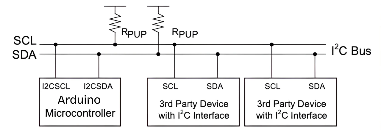
I2C uses two shared lines:
- SDA (Serial Data Line) — carries the data.
- SCL (Serial Clock Line) — carries the timing signal that synchronizes transfers.
Every device on the bus has a unique 7-bit address. The master (your Arduino) uses that address to select which device it is talking to. All other devices ignore the transmission. This is how one Arduino can communicate with dozens of sensors over the same two wires.
I2C Signals
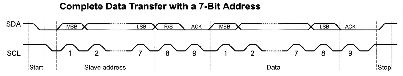
Every I2C transaction follows this sequence:
- Start condition — the master pulls SDA low while SCL stays high. This signals all devices that a new transmission is starting.
- Address + R/W bit — the master sends the 7-bit slave address followed by a read (1) or write (0) bit.
- ACK — after each byte, the receiving device pulls SDA low to confirm it received the data correctly.
- NACK — if SDA stays high after a byte, no device acknowledged. This usually means the address is wrong or the device is not connected.
- Stop condition — the master releases SDA high while SCL is high, marking the end of the transaction.
The Wire library handles all of this automatically. You do not need to generate start or stop conditions manually.
Speed Modes
| Mode | Max Speed |
|---|---|
| Standard Mode | 100 kHz |
| Fast Mode | 400 kHz |
| Fast Mode Plus | 1 MHz |
| High-Speed Mode | 3.4 MHz |
Most Arduino projects use Standard or Fast Mode. You can set the clock speed with Wire.setClock(400000) for Fast Mode. Higher speeds increase noise sensitivity, especially on long wires — keep I2C wires short.
Pull-up Resistors
I2C lines use open-drain outputs. Devices can only pull lines low — they cannot drive them high. Both SDA and SCL need pull-up resistors to hold the lines high when no device is pulling them low.
Use 4.7 kΩ resistors for most projects. Many breakout boards already include pull-ups. If you have multiple boards each with their own pull-ups, the combined resistance may be too low and cause communication errors — remove the extra ones if needed.
I2C Pins by Arduino Board
| Board | SDA Pin | SCL Pin |
|---|---|---|
| Arduino UNO / Nano | A4 | A5 |
| Arduino Mega 2560 | 20 | 21 |
| Arduino Leonardo / Micro | 2 | 3 |
| Arduino Due | 20 | 21 |
| Arduino UNO R4 | SDA | SCL (labeled near USB port) |
Most boards also have SDA and SCL labels printed directly on the header — use those if you are unsure. Some boards support multiple I2C ports, which is useful when connecting devices that share the same address.
Wire Library Functions
The Wire library is included with the Arduino IDE. You do not need to install anything.
#include <Wire.h>| Function | Description |
|---|---|
Wire.begin() | Initialize as I2C master |
Wire.begin(address) | Initialize as I2C slave at the given address |
Wire.setClock(freq) | Set bus speed in Hz (e.g. 400000 for Fast Mode) |
Wire.beginTransmission(address) | Start a write transaction to the given slave address |
Wire.write(data) | Queue a byte, array, or string for transmission |
Wire.endTransmission() | Send the queued data and release the bus |
Wire.requestFrom(address, n) | Request n bytes from a slave |
Wire.available() | Returns the number of bytes waiting to be read |
Wire.read() | Reads one byte from the receive buffer |
Wire.onReceive(function) | Register a callback for when slave receives data |
Wire.onRequest(function) | Register a callback for when master requests data from slave |
I2C Master — Writing Data
When Arduino acts as master, it initiates all communication. To write data to a slave:
- Call
Wire.beginTransmission(address)with the slave’s 7-bit address. - Queue data with
Wire.write(). - Call
Wire.endTransmission()to send it.
#include <Wire.h>

void setup() {
  Wire.begin();  // Initialize as master (no address argument)
}

void loop() {
  Wire.beginTransmission(0x27);  // Start transmission to device at 0x27
  Wire.write("Hello");           // Queue the data
  Wire.endTransmission();        // Send and release the bus
  delay(1000);
}This sends the string “Hello” every second to the device at address 0x27 — for example, an I2C LCD with a PCF8574 backpack. Always use the 7-bit address in Wire.beginTransmission(). The Wire library adds the read/write bit automatically.
I2C Master — Reading Data
To read data from a slave, use Wire.requestFrom() to ask for a specific number of bytes. Read them one at a time with Wire.read().
#include <Wire.h>

void setup() {
  Serial.begin(9600);
  Wire.begin();  // Initialize as master
}

void loop() {
  Wire.requestFrom(0x68, 2);    // Request 2 bytes from device at 0x68

  while (Wire.available()) {
    char c = Wire.read();       // Read one byte
    Serial.print(c);
  }

  delay(1000);
}Wire.requestFrom(address, quantity) sends a read request to the slave and stores the response in the receive buffer. Wire.available() tells you how many bytes are ready. This pattern is used to read sensor data from devices like the MPU6050 (accelerometer) or DS3231 (RTC).
I2C Slave — Setup and Callbacks
You can configure an Arduino to act as an I2C slave. A second Arduino, or any other I2C master, can then communicate with it using its assigned address.
#include <Wire.h>

void setup() {
  Wire.begin(0x08);              // Initialize as slave at address 0x08
  Wire.onReceive(receiveEvent);  // Called when master sends data
  Wire.onRequest(requestEvent);  // Called when master requests data
  Serial.begin(9600);
}

void loop() {
  delay(100);
}

void receiveEvent(int howMany) {
  while (Wire.available()) {
    char c = Wire.read();        // Read each received byte
    Serial.print(c);
  }
  Serial.println();
}

void requestEvent() {
  Wire.write("ACK");             // Send response to master
}Wire.begin(0x08) sets the Arduino as a slave at address 0x08. The master uses this address to reach it.
Wire.onReceive() and Wire.onRequest() register interrupt-driven callbacks — you do not need to poll for data in loop(). The library calls these functions automatically when the master sends data or requests a response.
When the master sends "Hello", receiveEvent() fires and prints each character to Serial. When the master calls Wire.requestFrom(0x08, 3), requestEvent() fires and sends back "ACK".
Replace Wire.write("ACK") with any data you need to return — a sensor reading, a status byte, or a temperature value.
I2C Scanner
Before writing your main program, run the I2C scanner to confirm your device is connected and find its address. This saves significant debugging time.
#include <Wire.h>

void setup() {
  Wire.begin();
  Serial.begin(9600);
  Serial.println("Scanning I2C bus...");
}

void loop() {
  byte error;
  int nDevices = 0;

  for (byte address = 1; address < 127; address++) {
    Wire.beginTransmission(address);
    error = Wire.endTransmission();

    if (error == 0) {
      Serial.print("Device found at 0x");
      if (address < 16) Serial.print("0");
      Serial.println(address, HEX);
      nDevices++;
    } else if (error == 4) {
      Serial.print("Unknown error at 0x");
      if (address < 16) Serial.print("0");
      Serial.println(address, HEX);
    }
  }

  if (nDevices == 0)
    Serial.println("No I2C devices found.");
  else
    Serial.println("Scan complete.");

  delay(5000);
}The scanner loops through all 127 possible 7-bit addresses and attempts a transmission to each one. If Wire.endTransmission() returns 0, a device acknowledged — its address is printed to Serial. If it returns 4, something responded but with an error.
Output
Once you upload this sketch and open the Serial Monitor (set to 9600 baud), you’ll see output like:
I2C Scanner Starting...
Scanning for I2C devices...
I2C device found at address 0x27 !
Scan complete.This confirms that a device was found at address 0x27, which you can now use in your main Arduino code.
If you don’t see any devices listed, double-check your SDA and SCL connections, pull-up resistors, and power supply.
I2C Addressing — 7-bit vs 8-bit
The Wire library uses 7-bit addresses. Always use the address from the device datasheet directly — do not shift it left or right. The library adds the read/write bit (the 8th bit) automatically.
Common device addresses:
| Device | Default Address |
|---|---|
| I2C LCD with PCF8574 | 0x27 or 0x3F |
| MPU6050 accelerometer | 0x68 (or 0x69 with AD0 high) |
| DS3231 / DS1307 RTC | 0x68 |
| SSD1306 OLED display | 0x3C or 0x3D |
| BMP180 / BMP280 | 0x76 or 0x77 |
| AT24C256 EEPROM | 0x50–0x57 |
If two devices share the same address, run the I2C scanner to confirm which is responding. You can then change one device’s address using its address pins (A0, A1, A2) if available.
Troubleshooting I2C
Device Not Found by Scanner
- Check that SDA connects to SDA and SCL connects to SCL. These are not interchangeable.
- Confirm the device has power — measure with a multimeter if needed.
- Check pull-up resistors are present on both SDA and SCL.
- Make sure you are using the correct board pins from the table above.
Garbled or Corrupt Data
- Run
Wire.setClock(100000)to drop to Standard Mode. High-speed communication over long or noisy wires causes errors. - Keep I2C wires short — under 30 cm for reliable communication at 400 kHz.
- Check that only one set of pull-up resistors is active on the bus. Multiple breakout boards with pull-ups each will load the line too heavily.
Two Devices with the Same Address
Each I2C address can only be used by one device on the bus. If two devices share an address:
- Check the device datasheet for address selection pins (often labeled A0, A1, A2). Tying these to HIGH or LOW changes the address.
- Some breakout boards have solder jumpers for address selection.
- If address modification is not possible, use an I2C multiplexer such as the TCA9548A. It gives you 8 separate I2C channels. You activate one channel at a time, so identical devices on different channels never conflict.
Voltage Mismatch
The Arduino UNO runs at 5V. Many modern sensors and modules run at 3.3V. Connecting a 3.3V device directly to a 5V I2C bus can damage it.
Use a bidirectional logic level shifter between the Arduino and any 3.3V device. Some breakout boards include a built-in level shifter — check the datasheet before connecting.
Bus Locked Up
If an interrupted transaction leaves SDA stuck low, the bus locks and nothing communicates. To recover:
- Power cycle all devices.
- If the problem recurs, toggle SCL manually 9 times to clock out the stuck byte, then issue a Stop condition.
Arduino I2C: Frequently Asked Questions
Conclusion
I2C is one of those protocols that feels abstract until you actually run the scanner sketch and see I2C device found at address 0x68 ! appear in the Serial Monitor. At that point, everything clicks — the two-wire bus, the 7-bit address, the ACK signal, the pull-up resistors — it all becomes concrete because you've seen the protocol actually responding.
Two things to always remember when adding a new I2C device to an existing project. First, run the scanner before writing any code. Confirm the device is responding at the expected address before trying to read from it. Second, check whether the new device already has a pull-up resistor on its breakout board. Multiple modules with their own pull-ups stacked on the same bus can overload the bus at higher clock speeds — you may need to remove one set or drop the clock to 100 kHz.
From here, the practical next steps depend on what you're building. If you want to output sensor data to a display over I2C, LCD1602 I2C with Arduino and SSD1306 OLED are both direct applications of what you've learned. If you're adding an RTC for timestamped logging, DS3231 Arduino tutorial uses the same Wire library patterns for beginTransmission, write, and requestFrom. For a multi-sensor project combining temperature, pressure, and humidity all on one I2C bus, BME280 with Arduino is the cleanest single-module example. And if you want the other half of serial communication, Arduino UART tutorial covers the complementary protocol — faster, longer range, point-to-point instead of multi-device.
Browse More Arduino Display Tutorials

SSD1306 Arduino OLED Tutorial: I2C Wiring, Text, Bitmaps & Animations
ST7735 Arduino TFT Tutorial: SPI Wiring, Graphics, Text & SD Card Image Display
Arduino SH1106 OLED Tutorial: I2C Wiring, Text, Bitmaps & Animations
How to Interface MAX7219 7 Segment Display with Arduino | Display Text, Scrolling Message, and Time
Arduino ST7920 Tutorial (128×64 LCD): Wiring, Setup, U8g2, and Text Display Guide

Subscribe
Login
0 Comments
Newest
