Home ▸ Arduino ▸ Displays & Interfaces ▸
Updated On: April 30, 2026
SSD1306 Arduino OLED Tutorial: I2C Wiring, Text, Bitmaps & Animations
The SSD1306 is a 0.96-inch monochrome OLED display that communicates over I2C using just two wires — SDA and SCL. It’s one of the most commonly used displays in Arduino projects because of its sharp 128×64 pixel output, ultra-low power draw, and wide library support.
In this tutorial, you’ll learn how to wire the SSD1306 to Arduino, find its I2C address, install the Adafruit SSD1306 and GFX libraries, and write code to display text, integers, floats, bitmaps, and multi-frame animations. All examples are tested on Arduino Uno and are directly usable with Nano and Mega. A complete project download is available at the end.
Before starting, a solid understanding of I2C will help — check out the Arduino I2C Tutorial if you need a refresher.
Working with other Arduino displays? Check out these related guides:
- SH1106 1.3″ OLED Display with Arduino
- I2C LCD1602 with Arduino
- ST7735 TFT Display with Arduino
- ST7920 128×64 Graphic LCD with Arduino
- ILI9341 TFT Touchscreen with Arduino
- MAX7219 7-Segment Display with Arduino
Browse the full Arduino Display Interfacing tutorial collection for more.

SSD1306 OLED Overview & Display Specifications
What Is the SSD1306 OLED Display?
The SSD1306 OLED display is a small yet powerful screen commonly used in embedded electronics projects. It’s based on an OLED (Organic Light Emitting Diode) panel, where each pixel emits its own light. This means there’s no need for a backlight, resulting in deep blacks, high contrast, and excellent visibility even in low light conditions.
The display is controlled by the SSD1306 driver IC, which handles communication with the microcontroller through interfaces like I2C or SPI. In this tutorial, we’ll focus on the I2C version, which uses just two data lines, SDA (Serial Data) and SCL (Serial Clock), making it ideal for projects with limited I/O pins.
Key Specifications & Features
The 0.96-inch SSD1306 OLED display is packed with useful features despite its small footprint. Below are the most common specifications you’ll find:
- Display Size: 0.96 inches (measured diagonally)
- Resolution: 128 × 64 pixels
- Driver IC: SSD1306
- Interface Type: I2C (can also be SPI on some modules)
- Operating Voltage: 3.3V to 5V
- Power Consumption: Very low, since OLEDs emit their own light
- Viewing Angle: Nearly 180 degrees
- Color: Typically monochrome (white, blue, or yellow variants available)

Each pixel on the OLED can be individually turned on or off, allowing you to display text, numbers, bitmaps, and simple animations. The high contrast ratio gives sharp and clear visuals, which makes it perfect for small handheld devices, IoT dashboards, or portable meters.
Why Use SSD1306 with Arduino?
There are several reasons why the SSD1306 OLED display is one of the most popular choices among Arduino enthusiasts:
- Simple Interface: Using the I2C protocol reduces wiring to just two pins, making it beginner-friendly and easy to integrate.
- Excellent Display Quality: OLED technology provides bright, high-contrast output with minimal power consumption.
- Compact and Lightweight: Ideal for small enclosures or battery-powered projects.
- Wide Library Support: The display is supported by popular libraries like Adafruit SSD1306 and Adafruit GFX, making programming effortless.
- Versatile Usage: From showing text and sensor values to creating cool startup animations, the SSD1306 can handle it all.
SSD1306 Arduino I2C Wiring & Connections
Required Components
Before connecting the OLED to Arduino, let’s gather all the components you’ll need for this project. The list is short, and all parts are easily available online or in local electronics stores.
You’ll need:
- Arduino Board – You can use Arduino Uno, Nano, or Mega (any board with I2C support will work).
- SSD1306 OLED Display (0.96″) – Make sure it’s the I2C version with four pins: GND, VCC, SDA, and SCL.
- Jumper Wires – For making connections between Arduino and OLED.
- Breadboard – Optional, but helpful for easy prototyping and testing.
That’s all you need! The hardware setup is very simple, which makes this project perfect for beginners who are learning about I2C communication with Arduino.
Wiring Diagram (Uno / Nano / Mega)
The I2C version of the SSD1306 display uses just two signal lines to communicate with Arduino, SDA (data line) and SCL (clock line). Along with these, you also need to connect power and ground.
The image below shows how the 0.96″ SSD1306 Oled display is connected to Arduino UNO.

Here’s how to connect it:
| OLED Pin | Connects To | Description |
|---|---|---|
| VCC | 5V (or 3.3V on some models) | Power supply for the display |
| GND | GND | Common ground |
| SDA | A4 (on Arduino Uno/Nano) | I2C Data line |
| SCL | A5 (on Arduino Uno/Nano) | I2C Clock line |
Note:
On the Arduino Mega, the I2C pins are SDA = Pin 20 and SCL = Pin 21. On newer boards like Arduino Leonardo, they are marked separately as SDA/SCL pins.
Once connected, your OLED display will communicate with Arduino over the I2C bus. The display typically uses the I2C address 0x3C, but some modules may use 0x3D — you can verify it using an I2C scanner sketch.
Find the I2C Address (0x3C / 0x3D)
To find your Oled I2C address, you can run a simple I2C scanner sketch on your Arduino:
#include <Wire.h>

void setup() {
  Wire.begin();
  Serial.begin(9600);
  Serial.println("Scanning for I2C devices...");
  for (byte i = 1; i < 127; i++) {
    Wire.beginTransmission(i);
    if (Wire.endTransmission() == 0) {
      Serial.print("I2C device found at address 0x");
      Serial.println(i, HEX);
    }
  }
}

void loop() {}Upload this code to your Arduino and open the Serial Monitor. You’ll see the detected I2C address printed there.
The image below shows the result of the I2C scanner code.
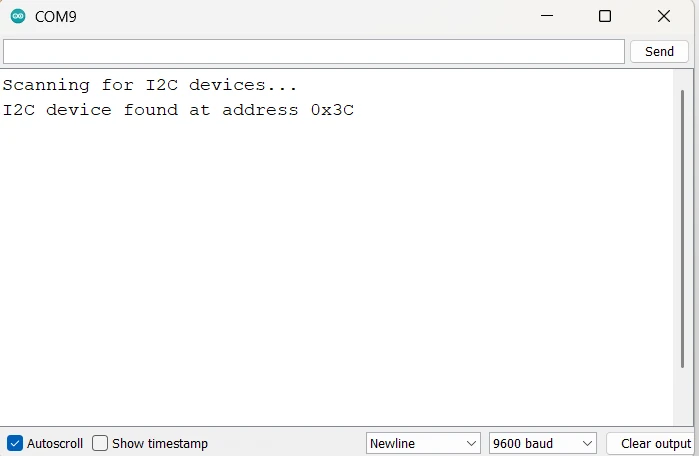
You can see the address 0x3C is detected by the scanner. We will use this address in our code later.
SSD1306 Library Setup & First Test
Once the hardware connection is done, the next step is to prepare your Arduino IDE so that it can communicate with the SSD1306 OLED display. We’ll use two official libraries from Adafruit that make working with the OLED display very simple — the Adafruit SSD1306 library and the Adafruit GFX library.
Install Adafruit SSD1306 and GFX Libraries
To begin, open your Arduino IDE and follow these steps:
- Go to the Sketch menu → Include Library → Manage Libraries…
- In the Library Manager, type “SSD1306” in the search bar.
- Find Adafruit SSD1306 by Adafruit and click Install.
- Next, search for “Adafruit GFX” and install Adafruit GFX Library as well.
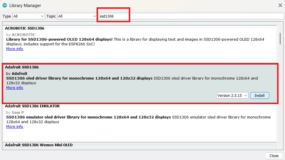
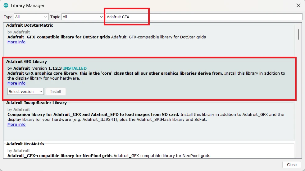
These two libraries work together, the SSD1306 library handles communication with the display, while the GFX library provides all the basic drawing functions such as drawing shapes, text, and bitmaps.
Note:
Always install the latest versions of these libraries to ensure compatibility and bug fixes. If you already have older versions installed, update them through the Library Manager.
After installing both libraries, you’ll have access to multiple example sketches that demonstrate how to use the OLED display effectively.
Run the Built-In Example Sketch
Now that everything is set up, let’s test the OLED display with a ready-made example.
- Open Arduino IDE and go to File → Examples → Adafruit SSD1306 → ssd1306_128x64_i2c.
- The example code includes the display setup and some demo text and graphics.
- In the code, find this line and ensure the I2C address matches your module:
#define SCREEN_ADDRESS 0x3CChange it to0x3Dif your display uses that address. - Select the correct board and COM port, then click Upload.

If everything is connected correctly, you should see the Adafruit logo appear first, followed by scrolling text and simple animations. This confirms that your display and Arduino are communicating successfully.
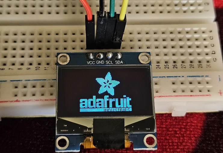
With this test complete, your setup is ready for custom code — you can now display your own text, numbers, and even animations on the OLED display.
SSD1306 Arduino Code: Text, Numbers & Bitmaps
Once the OLED display is working with the test sketch, the next step is to learn how to display your own text messages. The Adafruit GFX library provides simple and flexible functions to print text in different styles, sizes, and positions on the screen. This makes it easy to show messages, sensor readings, or any kind of data from your Arduino project.
Display Text on SSD1306 OLED
To print basic text on the SSD1306 OLED display, you first need to include the required libraries and initialize the display in your Arduino sketch.
Here’s a simple example:
#include <Wire.h>
#include <Adafruit_GFX.h>
#include <Adafruit_SSD1306.h>
#define SCREEN_WIDTH 128
#define SCREEN_HEIGHT 64
Adafruit_SSD1306 display(SCREEN_WIDTH, SCREEN_HEIGHT, &Wire, -1);
void setup() {
display.begin(SSD1306_SWITCHCAPVCC, 0x3C); // SSD1306_SWITCHCAPVCC = generate display voltage from 3.3V internally
display.clearDisplay();
display.setTextSize(1);
display.setTextColor(SSD1306_WHITE);
display.setCursor(0, 10);
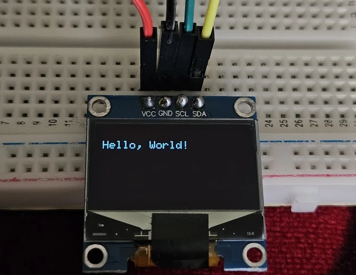
display.print("Hello, World!");
display.display();
}
void loop() {
}Here’s what’s happening in this code:
display.clearDisplay()clears any previous content on the screen.display.setTextSize(1)sets the default font size.display.setTextColor(SSD1306_WHITE)makes the text white on a black background.display.setCursor(0, 10)sets the text starting position in pixels.display.print("Hello, World!");prints the message on the display.- Finally,
display.display()sends everything from memory to the OLED screen.
Note:
The display only updates when you call display.display(). This helps reduce flicker and gives you control over when to refresh the screen.
The image below shows the output of the code on the oled display.
Adjust Text Size and Cursor Position
You can change the font size and cursor position easily using the Adafruit GFX functions. This is useful when you want to show headings, highlight values, or neatly arrange multiple text elements.
For example:
display.clearDisplay();
display.setTextSize(2);     // Larger text
display.setCursor(20, 20);  // Move text to new position
display.print("Arduino");
display.display();- The
setTextSize()function accepts integer values.- Size 1 is the smallest,
- Size 2 is double, and so on.
- The
setCursor(x, y)function positions the text wherexis the horizontal position andyis the vertical one.

You can experiment with different positions and sizes to make your display layout look more professional and easy to read.
Text Wrapping and Color Inversion
The Adafruit GFX library also includes options for text wrapping and inverting colors, which can enhance your display output.
- Text Wrapping:
By default, the library automatically wraps text when it reaches the edge of the display.
You can disable this behavior with:display.setTextWrap(false);This is useful when you want full control over text placement without automatic line breaks. - Inverted Text:
To make text stand out, you can invert the colors. This switches the text color to black on a white background.display.setTextColor(SSD1306_BLACK, SSD1306_WHITE);The first parameter sets the text color, and the second defines the background color.
Combining these features allows you to design dynamic and readable text layouts — for example, highlighting headings, displaying sensor names, or showing warnings on your OLED display.
Display Integer and Float Values
Printing numbers on the SSD1306 OLED display is just as easy as printing text. Whether you want to show sensor readings, counter values, or real-time measurements, the Adafruit GFX library provides simple methods to print both integers and floating-point numbers. You can even combine them with text for clear and informative displays.
Displaying Integer Values
To display integer values, you can directly use the display.print() or display.println() functions — just like you would use with the Serial Monitor.
Here’s a simple example that shows a counter increasing every second:
#include <Wire.h>
#include <Adafruit_GFX.h>
#include <Adafruit_SSD1306.h>

#define SCREEN_WIDTH 128
#define SCREEN_HEIGHT 64
Adafruit_SSD1306 display(SCREEN_WIDTH, SCREEN_HEIGHT, &Wire, -1);

int counter = 0;

void setup() {
  display.begin(SSD1306_SWITCHCAPVCC, 0x3C);
  display.clearDisplay();
  display.setTextSize(2);
  display.setTextColor(SSD1306_WHITE);
}

void loop() {
  display.clearDisplay();
  display.setCursor(10, 20);
  display.print("Count: ");
  display.print(counter);
  display.display();
  counter++;
  delay(1000);
}In this example:
- The variable
counterincreases by 1 every second. display.print(counter);shows the current count value.- Each time the display is updated, it clears the previous value to prevent overlapping text.
Note:
If you forget to use display.clearDisplay(), the old numbers might overlap with the new ones, making the display unreadable.
The gif below shows the output of the code.

Printing Floating Point Numbers with Precision
The Adafruit GFX library also allows you to display floating-point numbers directly using display.print(). You can control the number of decimal places by passing a second parameter to the print() function.
Example:
float temperature = 25.6789;
display.clearDisplay();
display.setCursor(10, 20);
display.setTextSize(2);
display.print("Temp: ");
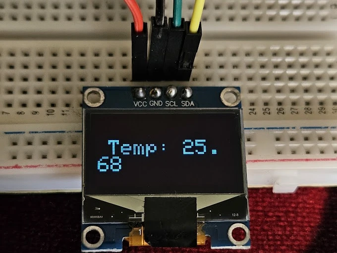
display.print(temperature, 2); // prints 25.68
display.display();
In the line display.print(temperature, 2);, the number 2 specifies that only two digits after the decimal point should be shown.
You can adjust this value depending on the precision you need — for example, use (temperature, 1) for one decimal place or (temperature, 3) for three.
This feature is very helpful for displaying sensor values such as temperature, voltage, or humidity, where accurate decimal representation is needed.
Note:
Avoid using too many decimal places because the OLED has limited space and smaller fonts may become hard to read.
The image below shows the float number displaying on the Oled.
Display Bitmaps on SSD1306 OLED
One of the best features of the SSD1306 OLED display is its ability to show custom graphics and logos. You can easily display icons, images, or even full-screen logos by using bitmap arrays. This opens up endless possibilities — from startup screens and battery indicators to creative graphics for your Arduino projects.
In this section, you’ll learn how to display static and dynamic bitmaps on your OLED using the Adafruit SSD1306 and Adafruit GFX libraries.
Understanding Bitmaps on OLED Displays
A bitmap is a collection of binary data that represents each pixel on the screen.
- Each bit in the array corresponds to one pixel.
- A value of 1 means the pixel is turned ON (white), while 0 means it’s OFF (black).
- Since the SSD1306 display is monochrome, there are no shades or colors — only black and white pixels.
You can use bitmaps to display small icons (like a Wi-Fi or battery symbol) or full-screen logos for branding your project.
Example of a simple 8×8 pixel bitmap:
const unsigned char myBitmap[] PROGMEM = {
  0x3C, 0x42, 0xA9, 0x85, 0xA9, 0x91, 0x42, 0x3C
};Here, each byte represents 8 pixels, and the pattern defines the shape to be displayed.
Converting Images to Bitmaps
To use your own image, you need to convert it into a C byte array. You can easily do this using the Image2CPP online tool.
The image below shows how to create bitmap using an existing image.
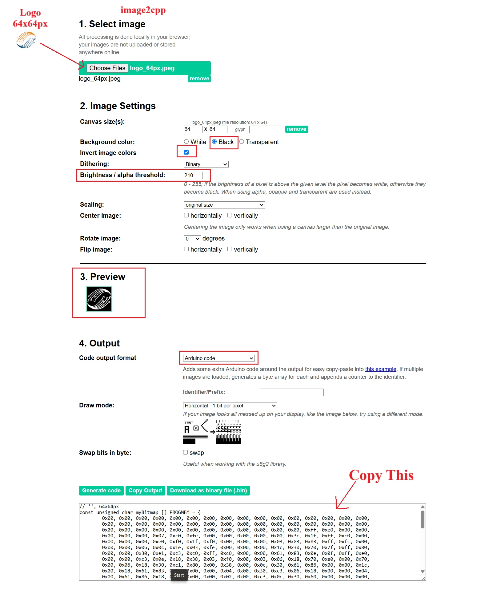
Follow these steps:
- Create a simple black-and-white image (for example, your logo).
- Upload it in Image2CPP.
- Configure the Image Settings. You can check the preview to see how the final image will look.
- Adjust the brightness/alpha threshold to generate clear image.
- Set output as Arduino Code.
- Choose Monochrome and Horizontal byte orientation.
- Click Generate Code and copy the byte array.
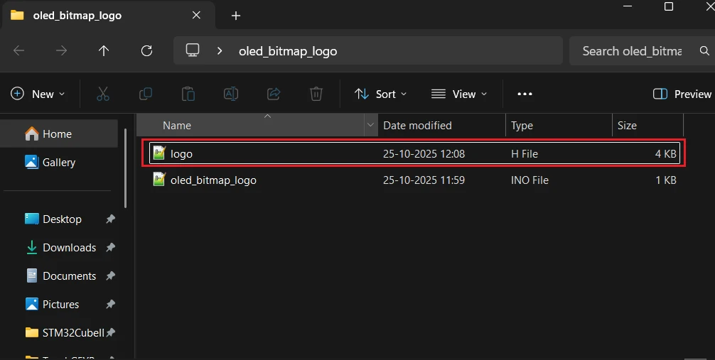
After copying the byte array, paste it in a new header file. It will keep the code clean as our image data will be in a separate file. In the image below, I have created a separate file named logo.h.

Now copy the file to the Arduino project folder, so that we can use it in the code.
Displaying a Bitmap Using Adafruit Library
To show your bitmap on the OLED, include the bitmap header file in the main file. Then use the drawBitmap() function provided by the Adafruit GFX library.
Here’s a simple example:
#include <Wire.h>
#include <Adafruit_GFX.h>
#include <Adafruit_SSD1306.h>
#include "logo.h"

#define SCREEN_WIDTH 128
#define SCREEN_HEIGHT 64
Adafruit_SSD1306 display(SCREEN_WIDTH, SCREEN_HEIGHT, &Wire, -1);

void setup() {
  display.begin(SSD1306_SWITCHCAPVCC, 0x3C);
  display.clearDisplay();
  display.drawBitmap(32, 0, myBitmap, 64, 64, SSD1306_WHITE);
  display.display();
}

void loop() {
}In the above code:
#include "logo.h"will include the bitmap header file.drawBitmap()draws the image starts at position (32, 0).- The parameters
(64, 64)specify the width and height of the image. SSD1306_WHITEturns the pixels ON.
You can adjust the x and y positions to move the image anywhere on the screen.
The image below shows the output of the above code. You can see the ControllersTech Logo is being displayed on the oled.
Combining Text and Bitmaps
You can mix text and graphics to make your OLED display more interactive. For example, show a Wi-Fi icon beside connection status text, or a battery symbol next to voltage readings.
Example:
display.drawBitmap(0, 0, wifiIcon, 16, 16, SSD1306_WHITE);
display.setCursor(20, 5);
display.setTextSize(1);
display.print("Connected");
display.display();This way, your display can look more professional, just like a mini dashboard interface.
Best Practices for Using Bitmaps
- Always clear the display before drawing new images:
display.clearDisplay(); - Use small icons (16×16, 32×32) for faster rendering.
- Store all bitmap data in PROGMEM to reduce RAM usage.
- Test image alignment by adjusting
xandycoordinates. - Avoid too many large bitmaps to prevent memory overflow.
SSD1306 Arduino Animations
The SSD1306 OLED display isn’t just for showing text and numbers — it’s also great for creating small, eye-catching animations. Whether you want to show a loading spinner, a bouncing object, or a moving logo, the Adafruit GFX library makes it possible by quickly updating frames on the screen.
In this section, we’ll understand how OLED animation works, how to use bitmap images, and how to design simple frame-based animations like a bouncing ball.
How OLED Frame Animation Works
Animations on OLED displays work by displaying a sequence of frames very quickly, just like a flipbook. Each frame represents one stage of motion. When frames change fast enough, the human eye perceives smooth movement.
The key steps are:
- Clear the display (
display.clearDisplay()) - Draw new graphics or text for the next frame
- Show the frame (
display.display()) - Add a small delay before updating the next frame
Here’s a simple structure for smooth animation:
display.clearDisplay();
display.drawCircle(x, y, 3, SSD1306_WHITE);
display.display();
delay(30);Each time the loop runs, you update the position (x and y) of the object. The shorter the delay, the smoother the animation — but too short a delay can make the motion too fast or flickery.
Note:
A delay between 20 to 50 milliseconds usually gives smooth animation without overloading the Arduino.
Example: Bouncing Ball Animation
Here’s a fun example — a small bouncing ball animation on the SSD1306 display:
#include <Wire.h>
#include <Adafruit_GFX.h>
#include <Adafruit_SSD1306.h>

#define SCREEN_WIDTH 128
#define SCREEN_HEIGHT 64
Adafruit_SSD1306 display(SCREEN_WIDTH, SCREEN_HEIGHT, &Wire, -1);

int x = 10, y = 10;
int xSpeed = 2, ySpeed = 2;

void setup() {
  display.begin(SSD1306_SWITCHCAPVCC, 0x3C);
  display.clearDisplay();
}

void loop() {
  display.clearDisplay();

  // Draw ball
  display.fillCircle(x, y, 3, SSD1306_WHITE);

  // Update position
  x += xSpeed;
  y += ySpeed;

  // Bounce from edges
  if (x <= 3 || x >= SCREEN_WIDTH - 3) xSpeed = -xSpeed;
  if (y <= 3 || y >= SCREEN_HEIGHT - 3) ySpeed = -ySpeed;

  display.display();
  delay(20);
}How it works:
- The ball moves by updating its position in each loop.
- When it reaches a boundary, its speed reverses direction — creating a bouncing effect.
- The short delay of 20 ms keeps the animation smooth and steady.
The gif below shows the animation on the bitmap.

This simple logic can be expanded to make more complex motions, such as multiple bouncing objects, logos, or even animated characters.
Custom Multi-Frame Bitmap Animations
Creating your own custom animations on the SSD1306 OLED display is one of the most exciting parts of using this module. You can design unique motion effects, such as moving icons, rotating logos, or sensor-based visualizations, by displaying a series of bitmap frames in quick succession.
In this section, we’ll go step by step through the process of designing, converting, and displaying your own animation frames on the OLED screen.
Converting Images to Bitmaps
To display any custom animation, you first need to convert your images into bitmap arrays that Arduino can understand. Since the SSD1306 is a monochrome display, all images must be black and white.
You can follow the process of converting image to Bitmap mentioned above. To simulate an animation, you need to convert multiple frames and save them different header files, for example, frame1.h, frame2.h, frame3.h etc.
Displaying Custom Frames in a Loop
Once you’ve converted your images, it’s time to display them in sequence to form an animation.
Here’s an example of how to loop through several bitmap frames:
#include <Wire.h>
#include <Adafruit_GFX.h>
#include <Adafruit_SSD1306.h>

#define SCREEN_WIDTH 128
#define SCREEN_HEIGHT 64
Adafruit_SSD1306 display(SCREEN_WIDTH, SCREEN_HEIGHT, &Wire, -1);

#include "frame1.h"
#include "frame2.h"
#include "frame3.h"

void setup() {
  display.begin(SSD1306_SWITCHCAPVCC, 0x3C);
  display.clearDisplay();
}

void loop() {
  display.clearDisplay();
  display.drawBitmap(0, 0, frame1, 64, 32, SSD1306_WHITE);
  display.display();
  delay(100);

  display.clearDisplay();
  display.drawBitmap(0, 0, frame2, 64, 32, SSD1306_WHITE);
  display.display();
  delay(100);

  display.clearDisplay();
  display.drawBitmap(0, 0, frame3, 64, 32, SSD1306_WHITE);
  display.display();
  delay(100);
}Each frame is drawn and displayed for a short duration (100 ms here) before switching to the next. Adjusting the delay changes the animation speed — shorter delays result in smoother motion.
Combining Multiple Frames for Motion Effect
To make your animation look more natural, use more frames with slight differences between them. For example, a rotating fan can be drawn in 4 or 6 positions to create the illusion of spinning.
You can store all your frames in an array and loop through them programmatically instead of repeating code blocks.
Example: In this example, I am using cat eye animation. I use this gif to extract the individual frames and then converted them to arrays.
#include <Wire.h>
#include <Adafruit_GFX.h>
#include <Adafruit_SSD1306.h>
#include "cat_animation.h"

#define SCREEN_WIDTH 128
#define SCREEN_HEIGHT 64
Adafruit_SSD1306 display(SCREEN_WIDTH, SCREEN_HEIGHT, &Wire, -1);

void setup() {
  display.begin(SSD1306_SWITCHCAPVCC, 0x3C);
  display.clearDisplay();
}

void loop() {
    for (int i = 0; i < 3; i++) {
    display.clearDisplay();
    display.drawBitmap(0, 0, cat_allArray[i], 128, 64, SSD1306_WHITE);
    display.display();
    delay(80); // frame delay for blinking effect
  }
}The gif below shows the animation on the Oled Display.

Tips for Smooth OLED Animations
Creating fluid animations on a small display like the SSD1306 requires efficient coding. Here are some useful tips:
- Keep frame updates minimal: Only redraw what changes, instead of clearing and redrawing everything each time.
- Reduce delay: Smaller delays make animations smoother but increase CPU usage — find a balance between speed and performance.
- Optimize bitmap size: Large bitmaps slow down rendering. Stick to small images for best results.
- Use loops efficiently: Avoid unnecessary calculations inside your loop. Keep only the motion logic.
- Manage power wisely: OLEDs consume power when pixels are ON. Dim or turn off unused sections to save energy.
By combining these tips, you can design creative and professional-looking animations on your Arduino SSD1306 OLED display, from simple loaders to fun startup sequences or sensor motion effects.
SSD1306 Arduino — Frequently Asked Questions
Conclusion
The SSD1306 is one of the most practical displays you can add to an Arduino project. In under an hour, you can go from bare wiring to a live display showing sensor values, custom logos, or smooth animations — all over two I2C wires.
In this tutorial, you covered the full workflow: wiring the display, scanning for the I2C address, installing the Adafruit libraries, and writing code to output text, integers, floats, bitmaps, and multi-frame animations. The bouncing ball and cat eye examples show just how capable this tiny panel is, even without external memory or a co-processor.
From here, you can combine the SSD1306 with sensors like the MPU6050 or BME280 to build live instrument dashboards, or explore the larger SH1106 1.3" OLED if you need more screen real estate. Download the full project below and explore the Arduino Display tutorials collection for the next step.
Download SSD1306 Arduino OLED Project Files
Complete Arduino project with text display, integer and float output, bitmap rendering, bouncing ball animation, and multi-frame cat eye animation. Includes logo.h and cat_animation.h bitmap headers. Free to download — support the work if it helped you.
Browse More Arduino Display Tutorials
ST7735 Arduino TFT Tutorial: SPI Wiring, Graphics, Text & SD Card Image Display
Arduino SH1106 OLED Tutorial: I2C Wiring, Text, Bitmaps & Animations
How to Interface MAX7219 7 Segment Display with Arduino | Display Text, Scrolling Message, and Time
Arduino ST7920 Tutorial (128×64 LCD): Wiring, Setup, U8g2, and Text Display Guide
Arduino ST7920 Display Graphics Guide: Shapes, Icons, Bitmaps, and UI Design

Subscribe
Login
0 Comments
Newest
