
Home ▸ Arduino ▸ Core Tutorials ▸
Updated On: June 1, 2026
Arduino UNO Pinout – Complete Guide with Diagram
If you are just getting started with Arduino, the first thing that confuses most people is the pins. There are so many of them, and it is not always clear what each one does.
In this guide, we are going to walk through every pin on the Arduino UNO board. We will explain what it does, when to use it, and what to watch out for. By the end, you will have a solid understanding of the Arduino UNO pinout and feel confident wiring up your next project.
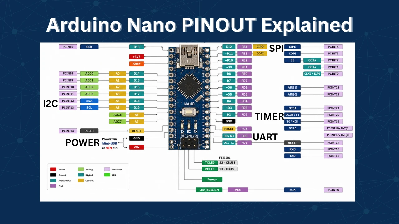
If you have Nano, read the Arduino Nano Pinout guide — a lot of what the UNO does is identical to the Nano. And once you are done with the pinout, the Arduino Core Tutorials page is where to go next. It covers GPIO, ADC, UART, I2C, SPI, PWM, and interrupts — all with working code examples.
Arduino UNO Specifications
Before we jump into the pins, let’s take a quick look at the board itself. The Arduino UNO is one of the most popular microcontroller boards out there, and for good reason. It is simple, affordable, and very well supported.
What is Arduino UNO?
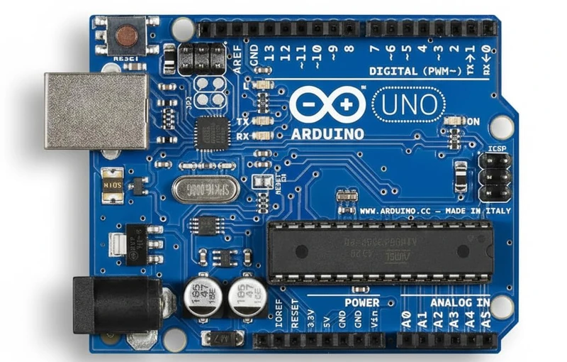
The Arduino UNO is a microcontroller board based on the ATmega328P chip. It runs at 16 MHz and has all the basic peripherals you need to build real-world embedded projects — digital I/O, analog input, PWM, and serial communication.
It is not the most powerful board, but it is the right one to start with. Once you understand how Arduino UNO works, moving to more advanced boards becomes a lot easier.
Key Specifications at a Glance
| Specification | Detail |
|---|---|
| Microcontroller | ATmega328P |
| Clock Speed | 16 MHz |
| Flash Memory | 32 KB (0.5 KB used by bootloader) |
| SRAM | 2 KB |
| EEPROM | 1 KB |
| Operating Voltage | 5V |
| Input Voltage | 6V – 12V (recommended 7–9V) |
| Digital I/O Pins | 14 (6 with PWM) |
| Analog Input Pins | 6 |
| Max Current per Pin | 40 mA |
| USB Interface | Type-B |
Arduino UNO Pinout Diagram
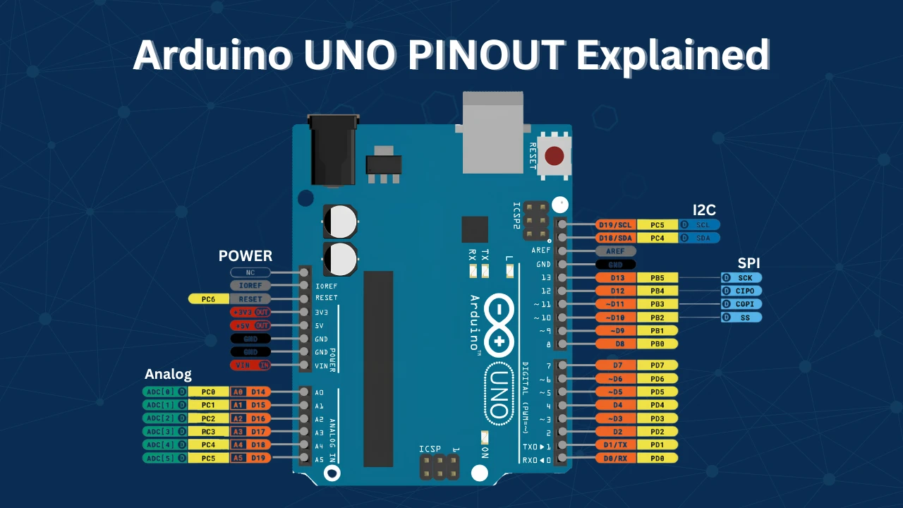
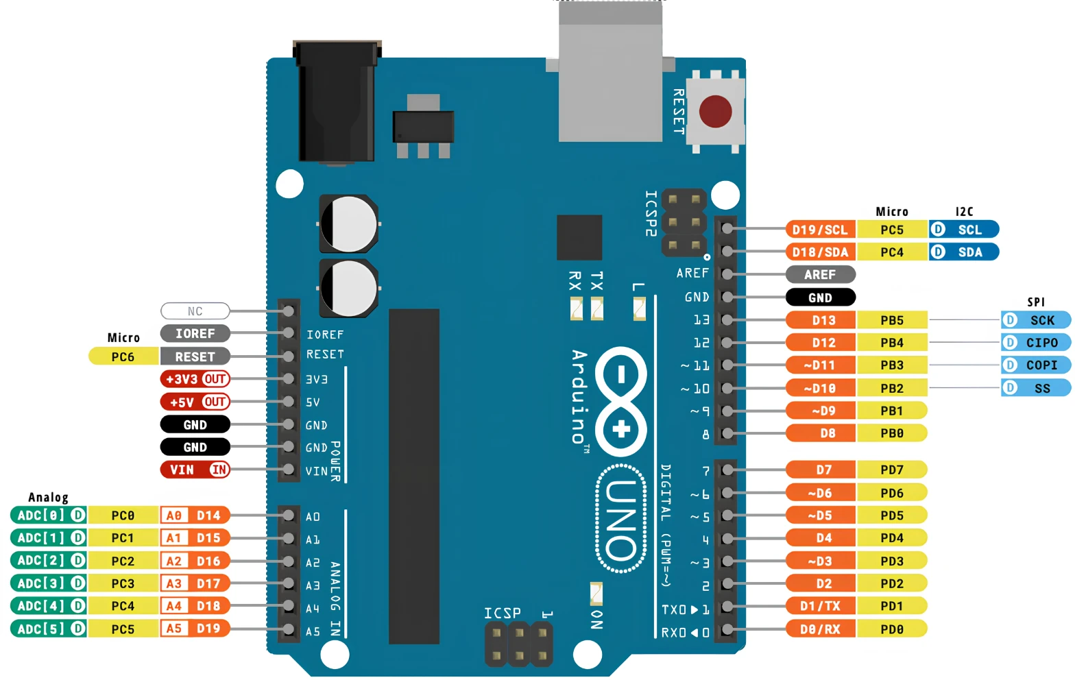
Here is the full pinout diagram for the Arduino UNO. I recommend keeping this open in another tab while reading the rest of the article.
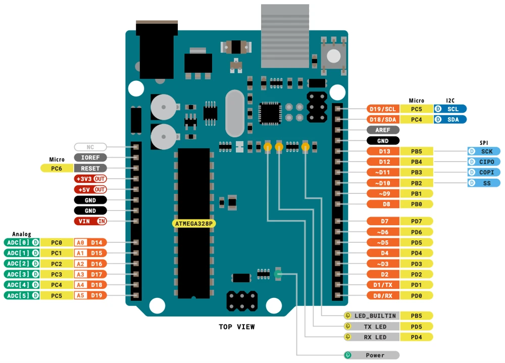
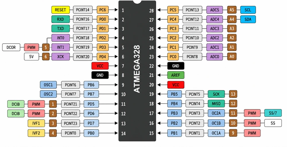
The pins are grouped into four main categories:
- Power Pins — for powering the board and external components
- Digital I/O Pins — for reading and writing digital signals
- Analog Pins — for reading analog voltages
- Communication Pins — for UART, I2C, and SPI
We will go through each group one by one.
Power Pins
The power section is on the left side of the board. This is where you supply power to the Arduino and also where you can draw power to run external components like sensors and modules.
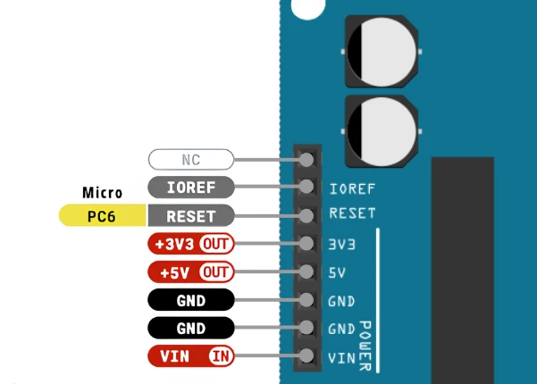
Let’s go through each pin here.
VIN Pin
VIN stands for Voltage Input. You can use this pin to supply external power to the Arduino UNO. The acceptable range is 6V to 12V, but I personally recommend staying between 7V and 9V. Going higher than that will cause the onboard regulator to get hot, and sustained high voltage will damage it over time.
So if you are powering your Arduino from a battery or an external supply, VIN is the pin to use.
5V Pin
This is a regulated 5V output from the onboard voltage regulator. You can use it to power sensors and modules that need 5V. Just be careful not to draw too much current from it, the onboard regulator can only handle so much load.
3.3V Pin
This pin gives you a regulated 3.3V output. It is useful when you are working with components that are not 5V tolerant, such as certain Bluetooth modules, Wi-Fi chips, or sensors that operate at 3.3V logic.
Keep in mind that this pin can only source up to 50 mA, so do not try to power anything heavy from it.
GND Pins
The Arduino UNO has three GND pins, and you can use any of them. They are all connected together internally.
One very important thing: whenever you connect an external module or sensor to Arduino, always make sure the grounds are shared. If the ground is not common, the signals will not read correctly.
RESET Pin
Pulling this pin LOW will reset the Arduino, just like pressing the physical reset button on the board. You will mostly use this when connecting Arduino to other systems that need to reset it programmatically.
IOREF Pin
This pin outputs the reference voltage that the Arduino I/O pins operate at — which is 5V for the UNO. It is mainly there for Arduino shields, so the shield can figure out whether it is connected to a 5V or 3.3V board and adapt accordingly.
You will rarely need to use this pin directly in your own projects.
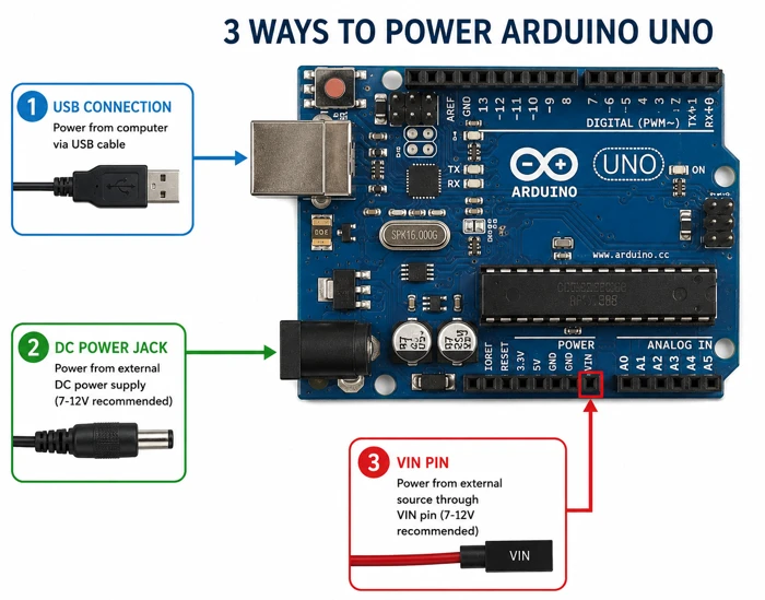
Key Points to Remember
- Never connect more than one power source at the same time (USB + VIN simultaneously can cause issues)
- Keep VIN between 7V–9V for safe operation
- Always share a common GND between Arduino and any external circuit
- The 3.3V pin is limited to 50 mA — do not overload it
Digital I/O Pins
The Arduino UNO has 14 digital I/O pins, labeled D0 to D13. These are the workhorses of the board. You will use them for almost everything — blinking LEDs, reading button presses, controlling relays, and more.
We can use the digitalRead() and digitalWrite() functions to read and write the digital pins. You can read the tutorial : Arduino digitalRead() and digitalWrite() Tutorial
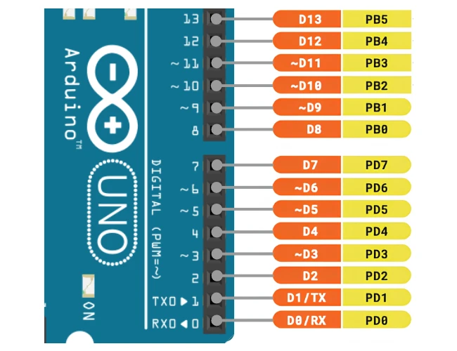
How Digital Pins Work
Each digital pin can be set as either an input or an output using the pinMode() function.
In output mode, the pin outputs:
- 5V when set HIGH
- 0V when set LOW
In input mode, the pin reads:
- HIGH if the voltage is between 2V and 5V
- LOW if the voltage is between 0V and 0.8V
Anything between 0.8V and 2V is an undefined state — you should avoid letting a pin float in that range.
Each pin can source or sink up to 40 mA of current. But do not treat 40 mA as a target — treat it as the hard limit you should never cross. For safe operation, stay under 20 mA per pin. Also, the total combined current across all I/O pins should not exceed 200 mA.
PWM Pins (~)
Six of the 14 digital pins also support PWM (Pulse Width Modulation). These pins are marked with a tilde (~) symbol on the board. They are: Pins 3, 5, 6, 9, 10, and 11.
You can go through the Arduino PWM Tutorial for more information on how to use it.
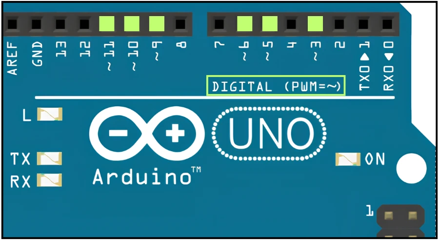
PWM lets you simulate an analog output by rapidly switching a pin between HIGH and LOW. You control the duty cycle using analogWrite(), which accepts a value from 0 (always LOW) to 255 (always HIGH).
Which Pins Support PWM?
| PWM Pin | Timer Used |
|---|---|
| Pin 3 | Timer2 |
| Pin 5 | Timer0 |
| Pin 6 | Timer0 |
| Pin 9 | Timer1 |
| Pin 10 | Timer1 |
| Pin 11 | Timer2 |
PWM Frequency and Resolution
The default PWM frequency on Arduino UNO is around 490 Hz for most pins, except pins 5 and 6 which run at 980 Hz. The resolution is 8 bits, giving you 256 steps from 0 to 255.
If you need more PWM pins, you can look into software PWM libraries, but keep in mind that software PWM puts extra load on the CPU.
Pin 13 – Built-in LED Pin
Pin 13 is special. It is connected to the onboard LED on the Arduino UNO board. This is why most beginner “blink” examples use pin 13 — you do not even need to wire anything up.
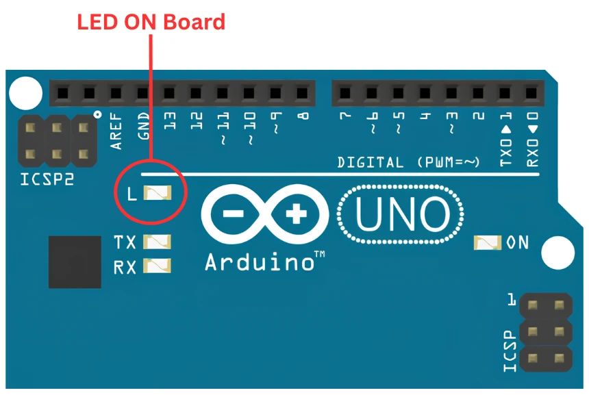
Just note that because of the onboard LED and its series resistor, pin 13 behaves slightly differently as an input compared to the other pins. So I would recommend avoiding using pin 13 as a digital input.
Key Points to Remember
- Always call
pinMode()before using a digital pin - Never exceed 40 mA per pin or 200 mA total across all pins
- Use resistors when connecting LEDs — 220Ω to 330Ω works well
- For motors, relays, or other high-current loads, always use a driver (transistor, MOSFET, or relay module)
- Avoid using pin 13 as a digital input due to the onboard LED circuit
Interrupt Pins
Interrupts are one of those features that make embedded programming a lot more powerful. Instead of constantly checking a pin in your main loop, you can tell the Arduino to pause whatever it is doing and immediately respond when a pin state changes.
This is much more efficient, and in some applications, it is the only reliable way to catch fast events.
External Interrupt Pins (INT0 and INT1)
The Arduino UNO has two dedicated external interrupt pins:
- INT0 → Digital Pin 2
- INT1 → Digital Pin 3
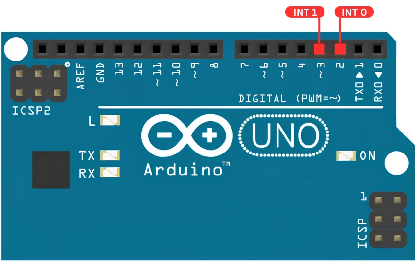
You attach an interrupt to these pins using attachInterrupt(). Each pin has its own interrupt vector, which means you can assign a separate handler function to each one.
You can go through the Arduino External Interrupt Tutorial to read more about it.
You can configure them to trigger on:
- RISING — when the pin goes from LOW to HIGH
- FALLING — when the pin goes from HIGH to LOW
- CHANGE — on any state change
- LOW — while the pin stays LOW
Pin Change Interrupts (PCINT)
If two interrupt pins are not enough, you can use Pin Change Interrupts (PCINT). Every digital pin on the Arduino UNO can act as a pin change interrupt source.
The difference is that PCINT pins do not each have their own interrupt vector. Instead, they are grouped by port, and all the pins in a port share a single interrupt. When it triggers, you have to manually check in your code which pin actually changed.
External Interrupts vs PCINT — What’s the Difference?
| Feature | External Interrupts (INT0/INT1) | Pin Change Interrupts (PCINT) |
|---|---|---|
| Dedicated pins | Only D2 and D3 | All digital + analog pins |
| Separate ISR per pin | Yes | No — shared per port |
| Trigger modes | RISING, FALLING, CHANGE, LOW | CHANGE only |
| Ease of use | Easy | Requires manual pin checking |
Use external interrupts (D2 and D3) whenever you can. Fall back to PCINT only when you need more interrupt sources.
Analog Pins
The Arduino UNO has six analog input pins, labeled A0 to A5. These are located on the bottom-left header of the board.
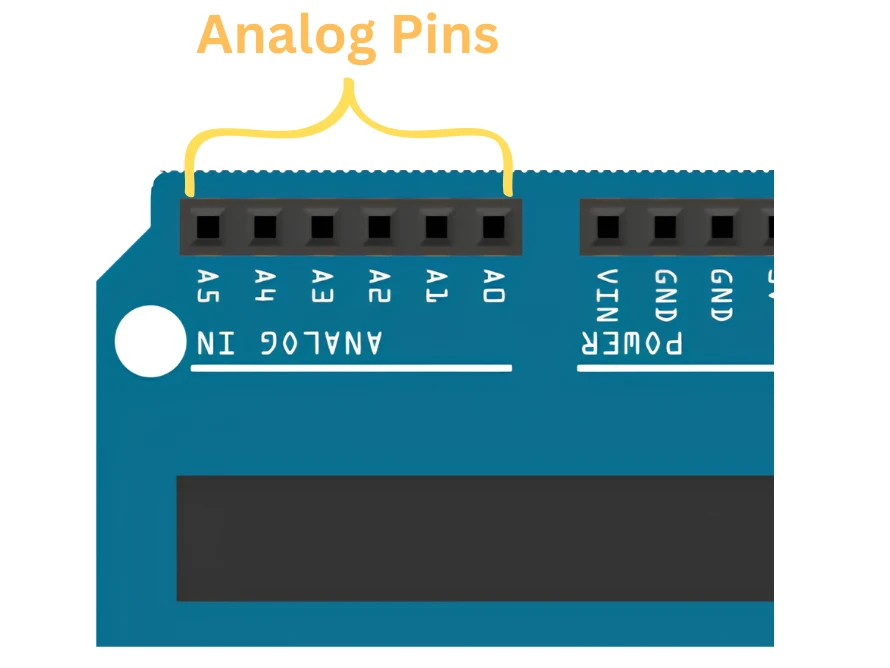
These pins are connected to the internal 10-bit ADC (Analog to Digital Converter) of the ATmega328P. You read them using analogRead(), which returns a value between 0 and 1023.
How Analog Pins Work
The ADC converts the analog voltage at the pin into a digital number. The formula is: ADC Value = (Input Voltage / VREF) × 1023
By default, VREF is 5V. So if you apply 2.5V to an analog pin, you will get a reading of around 511.
This gives you a resolution of about 4.9 mV per step — which is fine for most sensor readings.
You can go through the Arduino ADC and analogRead() tutorial to know more.
AREF Pin
The AREF (Analog Reference) pin lets you change the reference voltage used by the ADC. Instead of the default 5V, you can supply your own reference voltage to AREF.
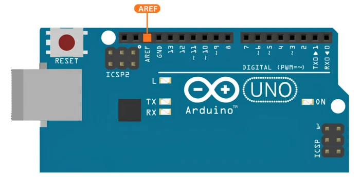
For example, if you connect 2.5V to the AREF pin and configure the ADC to use the external reference, your ADC range becomes 0V to 2.5V — effectively doubling the resolution for signals in that range.
This is useful when you are measuring small signals that never exceed a lower voltage. But make sure the analog input voltage never exceeds the AREF voltage you set, or you will get saturated readings.
Using Analog Pins as Digital I/O
You can also use the analog pins (A0–A5) as regular digital I/O pins. Just use pinMode() and digitalWrite() or digitalRead() on them — they work exactly the same way.
For example:
pinMode(A0, OUTPUT);
digitalWrite(A0, HIGH);This is handy when you run out of digital pins and need a couple more. Keep in mind though — once you use an analog pin as a digital output, you lose the ADC channel on that pin for as long as it is configured that way.
Key Points to Remember
- analogRead() returns 0–1023, mapped to 0V–5V by default
- Never apply more than 5V to an analog input pin
- Changing AREF increases resolution but limits your input voltage range
- A0–A5 can double as digital I/O pins when needed
Communication Pins
The ATmega328P supports three serial communication protocols — UART, I2C, and SPI. These let the Arduino talk to sensors, displays, modules, and other microcontrollers.
UART Pins (RX / TX)
UART (Universal Asynchronous Receiver-Transmitter) is the simplest and most commonly used serial protocol. On the Arduino UNO, the UART pins are:
- RX → Digital Pin 0
- TX → Digital Pin 1
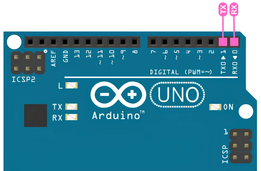
We mostly use UART to send debug messages to the Serial Monitor on your PC. But it is also used to interface things like:
- Bluetooth modules (HC-05, HC-06)
- GSM modules (SIM800L, SIM900)
- GPS modules (NEO-6M)
One important thing — do not connect anything to pins 0 and 1 while uploading code. The USB interface also uses these pins, and having them occupied will cause upload failures.
You can go through the Arduino UART tutorial to know more about it.
When to Use SoftwareSerial
The Arduino UNO has only one hardware UART. If you need a second serial port — for example, to talk to a Bluetooth module while still printing debug messages to the Serial Monitor — you can use the SoftwareSerial library.
SoftwareSerial lets you emulate a UART on any two digital pins. It works fine at lower baud rates (9600 or 115200), but it is not as reliable at higher speeds because it is bit-banging the protocol in software.
I2C Pins (SDA / SCL)
I2C (Inter-Integrated Circuit) is a two-wire protocol that lets you connect multiple devices on the same bus. The two pins are:
- SDA (Serial Data) → Analog Pin A4
- SCL (Serial Clock) → Analog Pin A5
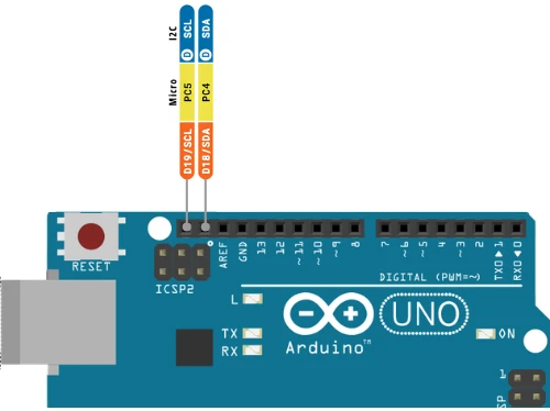
I2C is great because you can connect many devices on just two wires. Each device has a unique 7-bit address, so the Arduino can talk to each one individually. Common I2C devices include:
- OLED displays
- RTC modules (DS3231)
- MPU-6050 (gyroscope + accelerometer)
- I2C LCD displays
- External EEPROM chips
On the Arduino UNO, we use the Wire library to handle I2C communication. You can go through the Arduino I2C Tutorial to know more about how to use it.
Which Pins are I2C on Arduino UNO?
Just to be clear — A4 is SDA and A5 is SCL. If you are using I2C, these two pins are no longer available as analog inputs. That is worth keeping in mind when planning your pin usage.
SPI Pins (MOSI, MISO, SCK, SS)
SPI (Serial Peripheral Interface) is the fastest of the three protocols. It uses four wires:
- MOSI (Master Out Slave In) → Pin 11
- MISO (Master In Slave Out) → Pin 12
- SCK (Serial Clock) → Pin 13
- SS (Slave Select) → Pin 10
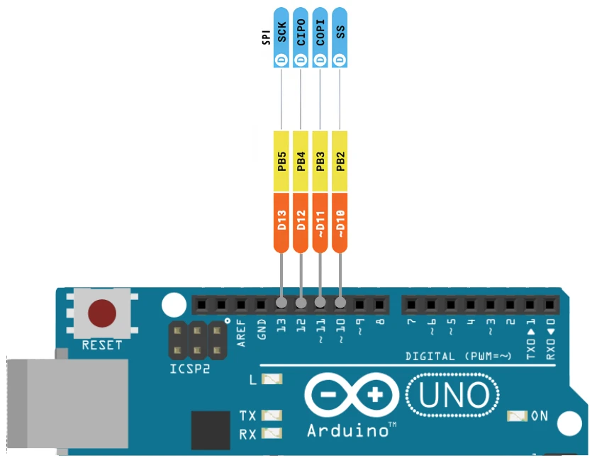
SPI is used when speed matters — things like TFT displays, SD card modules, nRF24L01 wireless modules, and external DAC/ADC chips.
The SS pin is what the master uses to select which slave it wants to talk to. If you have multiple SPI devices, you need a separate SS pin for each one. Pins 10–13 are taken by the SPI bus, so plan accordingly.
Timer and Input Capture Pins
Beyond the main categories, a few pins on the Arduino UNO have specific hardware functions tied to the timer modules inside the ATmega328P.
Timer/Counter Pins (T0 and T1)
Two pins can serve as external clock inputs for the hardware timers:
- T0 → Digital Pin 4 (external clock for Timer0)
- T1 → Digital Pin 5 (external clock for Timer1)
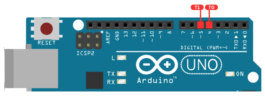
In normal operation, the timers use the internal 16 MHz clock. But if you connect an external clock signal to T0 or T1, the corresponding timer will count the incoming pulses instead.
This is useful for things like:
- Building a frequency counter
- Counting pulses from an optical encoder
- Using an external RTC crystal as a time base
Check an example of Arduino Time where we implement the microsecond delay in Arduino.
Input Capture Pin (ICP1)
The ICP1 (Input Capture Unit) pin is:
- ICP1 → Digital Pin 8
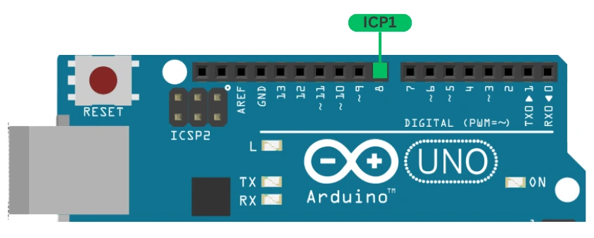
When a signal edge (rising or falling) is detected on this pin, the hardware automatically captures the current value of Timer1 and saves it to a register. This happens with zero CPU involvement, making it very precise for time-based measurements.
Common use cases include:
- Measuring the pulse width of a signal
- Reading an ultrasonic sensor (like HC-SR04) without blocking the CPU
- Measuring motor RPM with an encoder
Most Arduino libraries for ultrasonic sensors do not use ICU by default — they use pulseIn() which blocks the CPU. Using ICU directly is more advanced but gives you much better results.
Arduino UNO Pinout Summary Table
Here is a complete reference table for all the Arduino UNO pins. Keep this handy when wiring up your projects.
Digital Pins
| Arduino Pin | ATmega328P Port | PWM | Alternate Function | Description |
|---|---|---|---|---|
| D0 | PD0 | – | RX | UART Receive |
| D1 | PD1 | – | TX | UART Transmit |
| D2 | PD2 | – | INT0 | External Interrupt 0 |
| D3 | PD3 | ✓ | INT1 | External Interrupt 1 |
| D4 | PD4 | – | T0 | Timer0 External Clock |
| D5 | PD5 | ✓ | T1 | Timer1 External Clock |
| D6 | PD6 | ✓ | – | PWM Output |
| D7 | PD7 | – | – | General Purpose Digital I/O |
| D8 | PB0 | – | ICP1 | Input Capture Unit |
| D9 | PB1 | ✓ | – | PWM Output |
| D10 | PB2 | ✓ | SS | SPI Slave Select |
| D11 | PB3 | ✓ | MOSI | SPI Master Out Slave In |
| D12 | PB4 | – | MISO | SPI Master In Slave Out |
| D13 | PB5 | – | SCK / LED | SPI Clock / Onboard LED |
Analog Pins
| Arduino Pin | ATmega328P Port | Alternate Function | Description |
|---|---|---|---|
| A0 | PC0 | – | Analog Input / Digital I/O |
| A1 | PC1 | – | Analog Input / Digital I/O |
| A2 | PC2 | – | Analog Input / Digital I/O |
| A3 | PC3 | – | Analog Input / Digital I/O |
| A4 | PC4 | SDA | I2C Data / Analog Input |
| A5 | PC5 | SCL | I2C Clock / Analog Input |
| AREF | – | AREF | Analog Reference Voltage Input |
Power Pins
| Pin | Description |
|---|---|
| VIN | External supply input (6V–12V, recommended 7–9V) |
| 5V | Regulated 5V output from onboard regulator |
| 3.3V | Regulated 3.3V output (max 50 mA) |
| GND | Ground (3 pins, all connected internally) |
| RESET | Pull LOW to reset the microcontroller |
| IOREF | I/O voltage reference for shields (5V on UNO) |
Arduino UNO Pinout: Frequently Asked Questions
Conclusion
That covers the complete Arduino UNO pinout. We went through every pin on the board — from the power header to the digital and analog pins, all the way to the communication interfaces and special timer functions.
The Arduino UNO might look simple, but there is a lot packed into those pins. Understanding what each one does will save you a lot of debugging time and help you design better circuits from the start.
If you are just getting started, do not try to memorize everything. Bookmark this page and come back whenever you need a quick reference. The more projects you build, the more naturally these pins will stick in your memory.
Browse More Arduino Core Tutorials
Arduino digitalWrite() and digitalRead(): Complete Guide with Examples
Arduino UART Tutorial: Serial Communication, Send, Receive & LED Control
Arduino ADC and analogRead() Explained: Complete Guide with Examples
Arduino I2C Tutorial: Wire Library, Master/Slave, Scanner & Troubleshooting
Arduino delayMicroseconds() Tutorial: Precise Timing, Pulses & Alternatives

Subscribe
Login
0 Comments
Newest

