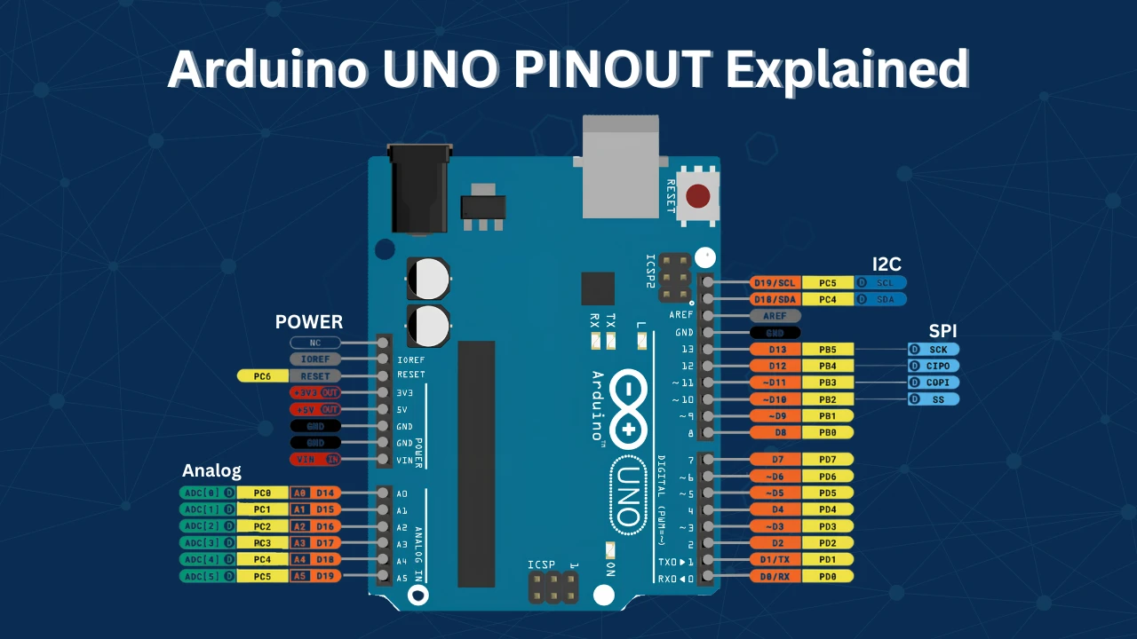
Home ▸ Arduino ▸ Core Tutorials ▸
Updated On: May 29, 2026
Arduino delayMicroseconds(): Precise Microsecond Timing with Examples
delayMicroseconds() pauses your Arduino sketch for a set number of microseconds. It is the function to use when delay() is too coarse — for generating sensor trigger pulses, bit-banging communication protocols, or controlling the timing of fast signals.
In this guide, you will learn:
- How
delayMicroseconds()works internally - Syntax, parameters, and allowed ranges
- A working pulse generation example with oscilloscope results
- Why the actual pulse is slightly longer than you specify — and how to fix it
- When to use
delayMicroseconds()and when to switch to something else
This is part of the Arduino Core Tutorials series. Related tutorials:
- analogRead() and ADC
- digitalWrite() and digitalRead()
- PWM and analogWrite()
- External interrupts
- UART serial communication
How delayMicroseconds() Works
delayMicroseconds() is a blocking busy-wait loop. When you call it, the CPU stops executing any other code and counts processor cycles until the requested time has passed. No other code runs. No interrupts are serviced (unless they were already pending). The processor is occupied for the full duration.
On a 16 MHz Arduino (UNO, Nano, Mega), one clock cycle is 62.5 nanoseconds. A 10 µs delay requires 160 clock cycles. The function calculates this count based on the board’s clock frequency and loops exactly that many times.
This makes it fast and predictable for short durations — but it also means your program is completely frozen during the delay.
Syntax
delayMicroseconds(time);time is an unsigned integer — the number of microseconds to wait.
delayMicroseconds(10);   // Pause for 10 microseconds
delayMicroseconds(500); // Pause for 500 microsecondsLimits and Accuracy
| Limit | Value |
|---|---|
| Minimum reliable delay | ~3 µs (values below this are inaccurate) |
| Maximum reliable delay | ~16,383 µs on 16 MHz boards |
| Recommended range | 3 µs to 1,000 µs |
Below 3 µs: The function’s own instruction overhead eats into the delay. A request for 1 or 2 µs may produce inconsistent results.
Above ~16 ms: The internal counter overflows on 16 MHz boards. Use delay() or millis() for longer waits instead.
Interrupts: If an interrupt fires during delayMicroseconds(), it extends the actual delay by however long the ISR takes. For timing-critical code, disable interrupts first with noInterrupts() and re-enable them after with interrupts().
noInterrupts();
delayMicroseconds(10);
interrupts();Pulse Generation Example
This example generates a 10 µs HIGH pulse on pin 8 every second — a common pattern for triggering sensors like the HC-SR04 ultrasonic module.
Code
const int pulsePin = 8;

void setup() {
  pinMode(pulsePin, OUTPUT);
}

void loop() {
  digitalWrite(pulsePin, HIGH);   // Pulse HIGH
  delayMicroseconds(10);          // Hold for 10 µs
  digitalWrite(pulsePin, LOW);    // End pulse
  delay(1000);                    // Wait 1 second before next pulse
}pinMode(pulsePin, OUTPUT) configures pin 8 as an output. Inside loop(), digitalWrite(HIGH) raises the pin to 5V, delayMicroseconds(10) holds it there for 10 µs, and digitalWrite(LOW) ends the pulse. The delay(1000) gives a 1-second gap between pulses so each one is easy to observe.
Results
The logic analyzer shows one short pulse per second, with the pin staying LOW between pulses.
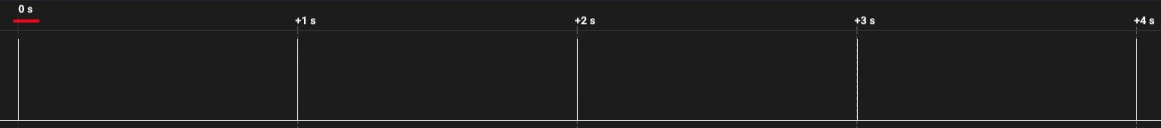
Zooming into a single pulse shows the exact duration:
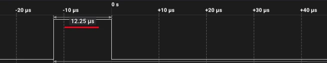
Why the Pulse is Slightly Longer Than 10 µs
The actual pulse width on the oscilloscope will be around 12–14 µs, not exactly 10 µs. This is expected and has two causes:
digitalWrite()overhead —digitalWrite()is a high-level Arduino function. It looks up the pin number, validates it, checks pin modes, and then sets the hardware register. This process takes approximately 3–5 µs on a 16 MHz Arduino. Both the HIGH and LOW calls add overhead around thedelayMicroseconds()call.- Instruction execution time — Setting up the delay loop itself takes a few CPU cycles before the counting even begins.
If you need an exact 10 µs pulse, use direct port manipulation instead of digitalWrite():
// Direct port manipulation — much faster than digitalWrite()
PORTB |= (1 << PB0);    // Set pin 8 HIGH (PB0 = Arduino pin 8)
delayMicroseconds(10);
PORTB &= ~(1 << PB0); // Set pin 8 LOWDirect port manipulation takes a single clock cycle (62.5 ns on 16 MHz), so the overhead is negligible. The pulse width will be very close to the requested value.
delayMicroseconds() vs Other Timing Methods
| Method | Resolution | Blocking | Use Case |
|---|---|---|---|
delayMicroseconds() | 1 µs | Yes | Short precise pulses, sensor triggers |
delay() | 1 ms | Yes | Simple waits where ms precision is enough |
micros() | 4 µs | No | Non-blocking timing, measuring elapsed time |
millis() | 1 ms | No | Non-blocking timing over longer periods |
| Hardware timers | < 1 µs | No | PWM, frequency generation, precise ISR timing |
Use delayMicroseconds() when:
- You need a blocking pause shorter than 1 ms
- You are generating a one-shot pulse (sensor trigger, IR signal bit, DHT22 start pulse)
- The rest of your code does not need to run during the delay
Switch to micros() or hardware timers when:
- Your program needs to keep running while tracking time
- You need delays longer than a few milliseconds
- You are generating repeated waveforms — use PWM or a timer interrupt instead
Non-Blocking Alternative with micros()
If you need µs-level timing without blocking the CPU, use micros():
unsigned long startTime = micros();

// Do other work here...

if (micros() - startTime >= 10) {
  // 10 µs have passed — take action
}micros() returns the number of microseconds since the Arduino started. It has a resolution of 4 µs on 16 MHz boards. Use it when your program cannot afford to freeze — for example, when reading multiple sensors or managing communication alongside timing.
Comparison: delay() vs delayMicroseconds()
| Feature | delay() | delayMicroseconds() |
|---|---|---|
| Unit | Milliseconds | Microseconds |
| Minimum value | 1 ms | ~3 µs |
| Maximum reliable value | Limited by unsigned long | ~16,383 µs |
| Blocking | Yes | Yes |
| Interrupt handling | Interrupts still fire | Interrupts can add timing error |
| Typical use | LED blink, debounce | Sensor pulses, protocol timing |
Tips for Accurate Microsecond Timing
Use noInterrupts() for critical timing. Background interrupt service routines — timer overflows, UART reception, millis() updates — fire every millisecond and add unpredictable jitter. Wrapping your pulse in noInterrupts() / interrupts() eliminates this.
Switch to direct port manipulation for sub-5-µs pulses. At this scale, digitalWrite() overhead is larger than the delay itself. Use PORTB, PORTD, or PORTC register writes instead.
Verify with an oscilloscope or logic analyzer. You cannot rely on calculated numbers alone for tight timing. Measure the actual pulse width and adjust the delayMicroseconds() argument to compensate for overhead.
Do not use it for long pauses. Values above 16,383 µs can overflow internally on 16 MHz boards. Use delay() for anything above 1 ms.
delayMicroseconds() Arduino: Frequently Asked Questions
Conclusion
delayMicroseconds() does one thing extremely well: it gives your Arduino a reliable, repeatable pause at the microsecond scale with zero setup — no timer configuration, no interrupt handler, just a single function call. For generating sensor trigger pulses, implementing 1-Wire or custom communication bit-banging, or inserting precise inter-step delays in stepper motor control, it is the right tool.
The two numbers to remember from this tutorial are 3 µs (minimum reliable delay on a 16 MHz board) and 16,383 µs (maximum before the internal calculation breaks). Below 3 µs, instruction overhead dominates and the actual pause is no longer proportional to the requested value. Above 16,383 µs, use delay() instead. And when your code needs to keep running while time passes — polling a sensor, reading Serial, or checking a button — micros() and millis() are always the right answer over any blocking delay function.
The logic analyzer output from the pulse generation example demonstrates the digitalWrite() overhead effect concretely: a delayMicroseconds(10) call produces a measured pulse of 12–13 µs because the digitalWrite(HIGH) and digitalWrite(LOW) calls each consume 2–3 µs of their own. If sub-microsecond pulse accuracy matters for your project, direct port manipulation or hardware PWM removes that overhead entirely.
The natural next step is Arduino PWM — the hardware timer approach to generating precise periodic waveforms without blocking loop() at all. For timing external events rather than generating them, Arduino External Interrupts fires a handler the instant a pin changes state — no polling, no delay, no missed edges. Download the full project above and explore the Arduino Core tutorials collection for more.
Download Arduino delayMicroseconds() Project Files
Complete Arduino sketches for microsecond delay timing: 10 µs pulse generation on pin 8 verified with a logic analyzer, direct port manipulation version for true 10 µs pulse width, and non-blocking pulse example using micros() for comparison. Compatible with Arduino Uno, Nano, and Mega (16 MHz boards). Free to download — support the work if it helped you.
Browse More Arduino Core Tutorials
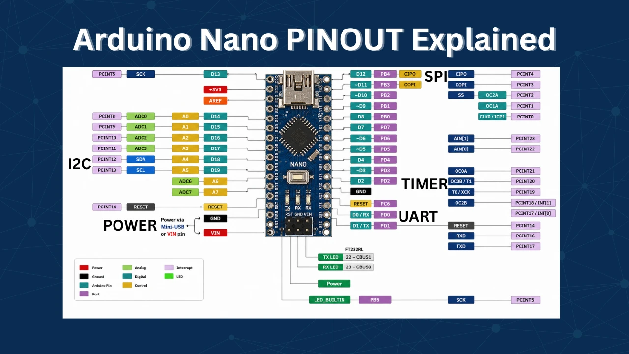
Arduino Nano Pinout – Complete Guide with Diagram
Arduino digitalWrite() and digitalRead(): Complete Guide with Examples
Arduino UART Tutorial: Serial Communication, Send, Receive & LED Control
Arduino ADC and analogRead() Explained: Complete Guide with Examples

Arduino I2C Tutorial: Wire Library, Master/Slave, Scanner & Troubleshooting

Subscribe
Login
0 Comments
Newest
