Home ▸ Arduino ▸ Sensors Interfacing ▸
Updated On: April 30, 2026
PIR Sensor Arduino Tutorial: Wiring, H/L Modes, Applications & Full Codes
The PIR (Passive Infrared) sensor detects motion by sensing the infrared radiation emitted by warm bodies — humans, animals, anything that moves and has heat. It outputs a clean digital HIGH on a single pin the moment motion is detected, with no library, no calibration code, and no complex protocol. Wire three pins, read one GPIO, and you have a working motion detector.
In this tutorial you’ll learn how the PIR sensor works internally, how to wire it to Arduino, and how to use every function the module offers — basic motion detection, H-Mode (output holds HIGH while motion continues), L-Mode (single pulse per trigger), sensitivity and delay-time adjustment via the onboard potentiometers, and a look at the Fresnel lens detection zones. You’ll also build three complete practical projects: a smart automatic light, an intruder alarm with a buzzer, and a motion-based people counter. All output is shown on the Serial Monitor, with LCD1602 I2C display examples as well. A full project download is included at the end.
Looking for other motion and proximity sensors on Arduino? Check out these related guides:
- IR Sensor with Arduino — Digital, Analog & LCD Output
- HC-SR04 Ultrasonic Distance Sensor with Arduino
- GP2Y0A41SK0F IR Distance Sensor with Arduino
- MPU6050 Accelerometer & Gyroscope with Arduino
- DHT11 & DHT22 Temperature & Humidity with Arduino
Browse the full Arduino Sensor Interfacing tutorial collection for more.
PIR Sensor Overview & How It Works
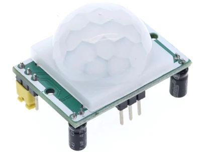
A PIR sensor is a simple and low-cost device used to detect motion. It works by sensing infrared radiation coming from warm objects like humans and animals. Every living body emits IR energy. When this energy changes suddenly, the PIR sensor identifies it as movement. Because of its high sensitivity and low power usage, the PIR module is widely used in home security systems, automatic lights, and smart automation projects.
Passive Infrared Detection Principle
The term “Passive” means the sensor does not send out any signals. It only receives infrared rays from the surroundings. Inside the PIR module, two IR-sensitive elements are placed side by side. When the environment is still, both elements receive the same amount of IR energy.
When a warm body moves across the sensor’s field, one element receives more IR than the other. This imbalance creates a small electrical signal. The internal circuitry then amplifies this signal and marks it as motion. This is the basic working principle of every PIR motion sensor.
Fresnel Lens and Detection Zones
The Fresnel lens on top of the PIR splits the detection area into multiple zones. When a warm object moves from one zone to another, the amount of IR hitting the sensing elements changes quickly. This sudden change is detected by the PIR circuitry.
Once motion is detected:
- The sensor output goes HIGH.
- Arduino reads the HIGH signal.
- The system triggers your action, such as alarm, light, display message, etc.
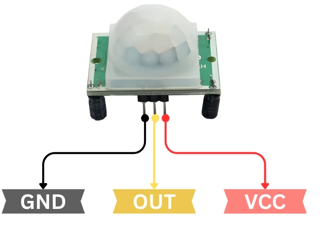
PIR Sensor Pinout — VCC, OUT, GND
Most PIR sensor modules have three pins:
- VCC – Connect to 5V
- OUT – Digital output signal
- GND – Ground
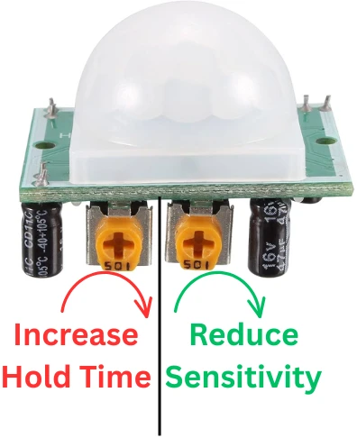
Sensitivity & Delay Potentiometers
You will also notice two adjustable knobs on the board:
- Sensitivity Control – Sets how far the sensor can detect motion.
- Delay Time Control – Sets how long the sensor stays HIGH after detecting motion.
H-Mode vs L-Mode Explained
Some modules also include a small switch for two operating modes:
- H Mode (Hold Mode) – Output stays HIGH while motion continues.
- L Mode (Non-Hold Mode) – Output goes HIGH once even if movement continues.
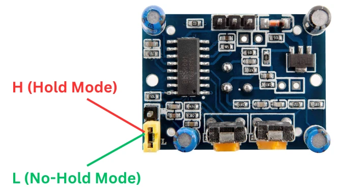
These features allow you to customize the sensor for different applications.
PIR Sensor Arduino Wiring & Setup
The Connection between a PIR motion sensor to an Arduino is very straightforward. The sensor outputs a digital HIGH whenever it detects motion, which the Arduino can easily read. In this section, we’ll walk through wiring the PIR sensor, adding the LCD1602 I2C display, and applying a few tips to ensure stable and accurate readings. The motion status will first appear on the Serial Monitor and then on the LCD screen.
Wiring Diagram — PIR Sensor to Arduino
Start by identifying the three pins on the PIR sensor: VCC, OUT, and GND.
- Connect PIR VCC to Arduino 5V
- Connect PIR GND to Arduino GND
- Connect PIR OUT to Arduino Digital Pin 2
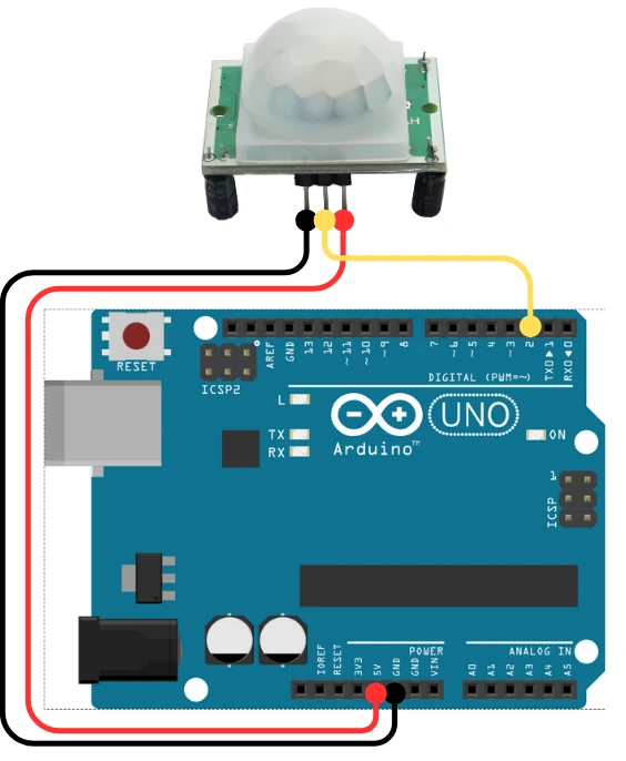
Once connected, the sensor will output a HIGH signal on the OUT pin whenever it detects movement in front of it. The Arduino continuously monitors pin D2 and reacts whenever it sees this HIGH state.
Before testing, give the PIR sensor 30–60 seconds to warm up after powering. During this time, it may give random triggers. Also, make sure the sensor is pointed toward an open area. Avoid directing it at heat sources, sunlight, or airflow, as these can cause false triggers.
Power and Stability Recommendations
To get consistent results from the PIR sensor, keep the following points in mind:
Power Tips
- Use a clean and stable 5V power supply.
- Keep the wiring short to reduce electrical noise.
- Always share the same ground between Arduino and the PIR sensor.
Range & Stability Tips
- Adjust the Sensitivity knob on the PIR to control how far it detects (typically up to 6–7 meters).
- Use the Delay knob to decide how long the output stays HIGH after detecting motion.
- Avoid placing the sensor in direct sunlight or near heaters.
- Keep it away from fans or strong airflow, as sudden temperature changes can cause false triggers.
PIR Sensor Arduino Code: All Modes & Outputs
The PIR sensor offers several useful functions. You can read basic motion, control how long the output stays HIGH, and adjust distance using the sensitivity knob. In this section, we will explore each feature with separate Arduino codes. All examples will show the result on the Serial Monitor first. Later, we will combine everything and display the output on the LCD1602 I2C screen as well.
Basic Motion Detection (Digital Read)
This is the simplest way to read the PIR sensor. The OUT pin becomes HIGH when motion is detected.
Below is the code to read the signal from PIR sensor.
int pirPin = 2;

void setup() {
  pinMode(pirPin, INPUT);
  Serial.begin(9600);
}

void loop() {
  int state = digitalRead(pirPin);

  if (state == HIGH) {
    Serial.println("Motion Detected");
  } else {
    Serial.println("No Motion");
  }

  delay(500);
}The Arduino reads the PIR output from pin 2. If the value is HIGH, motion is detected. If LOW, the area is clear. We will print the result on the serial console.
Serial Monitor Output
Below is the GIF showing the output of the code. The PIR sensor detects motion, and the result is printed on the serial console of the Arduino IDE.

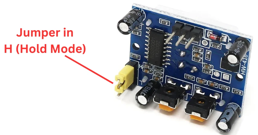
H-Mode — Hold Output While Motion Continues
In H-Mode, the PIR sensor keeps the output HIGH as long as motion continues. If the person keeps moving, the signal stays HIGH.
Jumper Configuration for H-Mode
Make sure to connect the jumper as shown in the image below.
Code & Serial Monitor Output
int pirPin = 2;

void setup() {
  pinMode(pirPin, INPUT);
  Serial.begin(9600);
  Serial.println("PIR Hold Mode Active");
}

void loop() {
  int state = digitalRead(pirPin);

  if (state == HIGH) {
    Serial.println("Motion Active - Holding");
  } else {
    Serial.println("No Motion");
  }

  delay(500);
}In H-Mode the output remains HIGH as long as the sensor is detecting motion. Therefore the serial console will keep showing motion. It is ideal for alarms and lights. Output stays HIGH until the movement stops.
Below is the GIF showing the output of the code. The PIR sensor detects motion in H-Mode, and as long as the motion continues, the Out pin remains HIGH. Hence the serial console shows the continuous motion.

L-Mode — Single Pulse per Motion Trigger
In L-Mode, the PIR output goes HIGH once when motion is detected. Even if the motion continues, it sends only a single HIGH pulse.
Below is the code to read the signal in L-Mode.
int pirPin = 2;
bool triggered = false;

void setup() {
  pinMode(pirPin, INPUT);
  Serial.begin(9600);
  Serial.println("PIR Non-Hold Mode Active");
}

void loop() {
  int state = digitalRead(pirPin);

  if (state == HIGH && !triggered) {
    Serial.println("Motion Triggered Once");
    triggered = true;
  }

  if (state == LOW) {
    triggered = false;
  }

  delay(100);
}In L-Mode the output goes HIGH just for a moment, even if the sensor is detecting motion. It is ideal for alarms and lights. Output stays HIGH until the movement stops.
Serial Monitor Output
Below is the gif showing the output of the code. The PIR sensor detects motion in L-Mode. Even if the motion continues, the Out pin goes HIGH just once.

Adjusting Sensitivity and Delay Time
PIR modules include two small onboard knobs:
1. Sensitivity Knob
- Controls motion detection range.
- Rotate clockwise for longer distance (up to 6–7 meters).
- Rotate anticlockwise for shorter range.
2. Delay Time Knob
- Controls how long the output stays HIGH.
- Can be adjusted from a few seconds to a few minutes.
- Turn clockwise for a longer delay.
Use these knobs to fine-tune detection for your environment and avoid false triggers.
PIR Sensor Arduino Project Examples
PIR sensors are widely used in real-world automation projects. With just a few lines of code, you can build motion-based lights, alarms, and even counting systems. In this section, we will explore three practical projects that use the PIR sensor with Arduino. Each idea is simple to build and perfect for beginners.
PIR Smart Light (Auto On/Off)
A PIR smart light turns ON automatically when motion is detected and turns OFF when the area is clear. This setup is useful for rooms, corridors, staircases, and bathrooms.
Below is the code to implement PIR based smart light.
int pirPin = 2;
int lightPin = 8;

void setup() {
  pinMode(pirPin, INPUT);
  pinMode(lightPin, OUTPUT);
  Serial.begin(9600);
}

void loop() {
  int state = digitalRead(pirPin);

  if (state == HIGH) {
    digitalWrite(lightPin, HIGH);
    Serial.println("Light ON - Motion Detected");
  } else {
    digitalWrite(lightPin, LOW);
    Serial.println("Light OFF - No Motion");
  }

  delay(300);
}This program switches the light ON when motion is present and OFF when the PIR output becomes LOW.
Output
Below is the gif showing the output of the code. The PIR sensor detects motion, and the LED turns on. After some time, the LED turns OFF automatically.

PIR Intruder Alarm with Buzzer
This project works like a basic security alarm. When the PIR sensor detects movement, the buzzer sounds an alert.
Below is the code to implement PIR based security Alarm.
int pirPin = 2;
int buzzerPin = 9;

void setup() {
  pinMode(pirPin, INPUT);
  pinMode(buzzerPin, OUTPUT);
  Serial.begin(9600);
}

void loop() {
  int state = digitalRead(pirPin);

  if (state == HIGH) {
    digitalWrite(buzzerPin, HIGH);
    Serial.println("Intruder Detected!");
  } else {
    digitalWrite(buzzerPin, LOW);
    Serial.println("Area Safe");
  }

  delay(300);
}When the PIR detects motion, the buzzer turns ON instantly. This is perfect for doorways and restricted areas.
Motion-Based People Counter
A motion counter increments a number each time the PIR detects movement. It can be used to count people entering a room, visitors at a shop, or animals passing through a gate.
Below is the code to implement Motion-Based counter system.
int pirPin = 2;
int count = 0;
bool triggered = false;

void setup() {
  pinMode(pirPin, INPUT);
  Serial.begin(9600);
  Serial.println("Motion Counter Ready");
}

void loop() {
  int state = digitalRead(pirPin);

  if (state == HIGH && !triggered) {
    count++;
    Serial.print("Count: ");
    Serial.println(count);
    triggered = true;
  }

  if (state == LOW) {
    triggered = false;
  }

  delay(100);
}The counter increases only once per motion trigger. It prevents multiple counts if the person stays in front of the sensor.
Output
The gif below shows the output. PIR sensor detects the motion and the counter increases. the result is printed on the serial console of the Arduino IDE.

Troubleshooting PIR Sensor Problems
When working with PIR sensors and Arduino, you may face issues like no detection, false triggers, or unstable readings. This section explains the common problems and how to solve them for reliable performance.
PIR Not Detecting Motion
- Ensure the sensor is powered with a stable 5V.
- Check the OUT pin wiring to the correct Arduino digital pin.
- Increase the sensitivity knob if the area is large.
- Make sure the lens is facing the motion without any obstruction.
- Allow 10–30 seconds warm-up time after powering the sensor.
False Triggers and Random Firing
- Keep the PIR away from fans, direct sunlight, heaters, or windows.
- Use shorter wires or shielded cables to reduce interference.
- Add a 100 µF capacitor between VCC and GND for stable power.
- Disable nearby sources of electrical noise (motors, relays).
- Avoid placing PIR near reflective surfaces.
Improving Detection Accuracy
- Point the PIR toward areas where motion naturally occurs.
- Adjust the delay time and sensitivity knobs as per room size.
- Use H-Mode for stable detection and L-Mode for fast response.
- Install the sensor at a height of 5–7 feet for maximum coverage.
- Use a fresher lens and clean the dome regularly for better detection.
PIR Sensor Arduino — Frequently Asked Questions
Conclusion
The PIR sensor is one of the most practical sensors in the Arduino ecosystem. No library, no address scanning, no conversion math — just three wires and a digitalRead() call, and you have reliable passive motion detection covering up to 7 meters.
In this tutorial you covered everything the module offers: how the Fresnel lens creates detection zones, how to wire the sensor and configure H-Mode versus L-Mode using the onboard jumper, how to tune sensitivity and hold time with the potentiometers, and how to build three real-world applications — an automatic light, an intruder alarm, and a motion counter — all verified live on the Serial Monitor.
From here you can add an SSD1306 OLED for a compact standalone display, combine the PIR with a relay module to switch mains-voltage lights, or pair it with an IR sensor for directional entry/exit counting. Download the full project above and explore the Arduino Sensor Interfacing series for the next build.
Download PIR Sensor Arduino Project Files
Complete Arduino project with basic motion detection, H-Mode and L-Mode sketches, PIR smart light, intruder alarm with buzzer, and motion-based counter code. No external libraries required — uses only built-in Arduino functions. Free to download — support the work if it helped you.
Browse More Arduino Sensors Tutorials
SHT21 Arduino Tutorial: I2C Wiring, SHT2x Library, Serial & LCD Output
AHT20 Arduino Tutorial: I2C Wiring, Adafruit AHTX0 & OLED Display

SHT30 / SHT31 / SHT35 Arduino Tutorial: I2C Wiring, Code & LCD1602 Display
DS18B20 Arduino Tutorial: Single & Multiple Sensors, Serial & OLED Output

BMP180 Arduino Tutorial: I2C Wiring, Temperature, Pressure, Altitude & LCD1602

Subscribe
Login
0 Comments
Newest
