Home ▸ Arduino ▸ Sensors Interfacing ▸
Updated On: April 30, 2026
IR Sensor Arduino Tutorial: Digital Output, Analog Distance & LCD Display
The IR sensor module is one of the simplest and most versatile components you can add to an Arduino project. It uses an infrared LED and a photodiode to detect nearby objects — no library needed, no complex protocol. Just three wires and a digitalRead() or analogRead(), and you have a fully working obstacle detector.
In this tutorial, you’ll learn how to wire the IR sensor to Arduino, use it in digital detection mode (HIGH/LOW object present/absent), read the analog output for short-range distance values, adjust sensitivity using the onboard potentiometer, and display live readings on both the Serial Monitor and an LCD1602 I2C display. You’ll also build a practical automatic object counter. A complete project download is included at the end.
Working with other detection and distance sensors on Arduino? Check out these related guides:
- HC-SR04 Ultrasonic Distance Sensor with Arduino
- GP2Y0A41SK0F IR Distance Sensor with Arduino
- PIR Motion Sensor with Arduino
- MPU6050 Accelerometer & Gyroscope with Arduino
- ADXL345 Accelerometer with Arduino
Browse the full Arduino Sensor Interfacing tutorial collection for more.
IR Sensor Overview & How It Works
In this section, we learn how an IR sensor works, what components it uses, and why it is popular in Arduino projects. Knowing the basics will help you understand the readings and fix issues later.
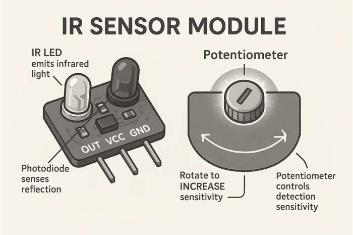
IR LED + Photodiode Detection Principle
An IR sensor uses an IR LED and a Photodiode to detect objects.
- The IR LED emits infrared light.
- When an object comes close, this light reflects back.
- The Photodiode receives the reflected light.
- The module processes this change and gives an output to Arduino.
Most modules also include a comparator (Op-Amp), a sensitivity knob, and indicator LEDs.
Here is a quick summary:
| Component | Function |
|---|---|
| IR LED | Emits infrared light towards the object |
| Photodiode | Detects reflected IR light |
| Op-Amp Comparator | Converts light intensity into HIGH/LOW |
| Potentiometer | Adjusts detection sensitivity |
| Status LED | Shows when an object is detected |
Digital vs Analog IR Sensor Output
IR modules generally provide either digital output, analog output, or both.
| Type | Output | Behavior | Common Use |
|---|---|---|---|
| Digital IR Sensor | HIGH/LOW | LOW = object detected | Line follower, obstacle detection |
| Analog IR Sensor | 0–1023 value | Value increases as object comes closer | Distance measurement |
| Dual Output Sensor | DO + AO | Supports both modes | Flexible projects |
Digital sensors are simple and great for beginners. Analog sensors offer more accuracy for short-range distance.
IR Sensor Pinout & Technical Specifications
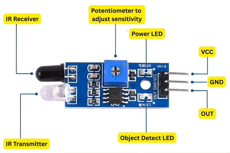
Most IR sensor modules have 3 pins, while some advanced ones have 4 pins.
The image below shows the pinout of IR sensor with 3 pin module.
The table blow explains the function of each pin
| Pin | Description |
|---|---|
| VCC | Power supply (3.3V – 5V) |
| GND | Ground |
| OUT / DO | Digital Output |
| AO (optional) | Analog Output |
Technical Specifications
| Specification | Typical Value |
|---|---|
| Operating Voltage | 3.3V to 5V |
| Detection Range | 2 cm – 30 cm |
| Output Type | Digital / Analog |
| Sensitivity Adjustment | Yes, using a potentiometer |
| Indicator LED | Yes, detection status |
These features make the IR sensor easy to use in Arduino projects.
IR Sensor Arduino Wiring & Connections
This section shows the simple wiring between the IR sensor module and Arduino. You will connect the sensor, upload a small test sketch, and check the output on the Serial Monitor. This helps you confirm that your IR module is working correctly before moving to advanced features.
Wiring Diagram — IR Sensor to Arduino
Connecting the IR sensor to an Arduino is very simple. The module usually has three pins: VCC, GND, and OUT.
The image below shows the connection between Arduino Uno and IR sensor module.
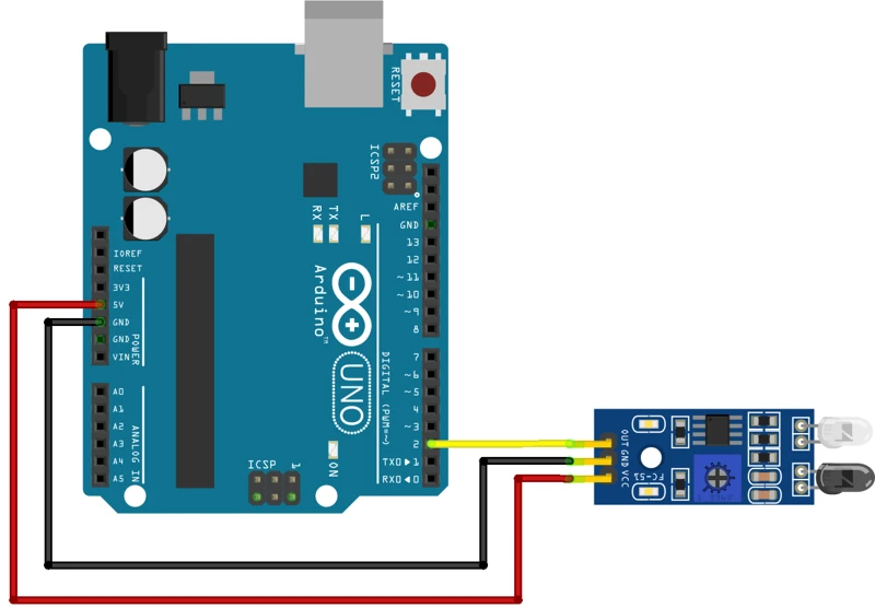
The table below explains the wiring diagram.
| IR Sensor Pin | Arduino Pin |
|---|---|
| VCC | 5V |
| GND | GND |
| OUT (Digital) | D2 (any digital pin) |
This wiring uses digital mode because most basic IR sensors provide a HIGH/LOW output. When nothing is in front of the sensor, the output stays HIGH. When an object comes close, the output becomes LOW.
Make sure:
- The sensor faces forward
- The sensitivity potentiometer is not turned all the way up or down
- You keep your hand 2–10 cm in front of the sensor for testing
Basic Digital Output Test
Upload this simple sketch to check if your IR sensor is working:
int irPin = 2;  // Digital pin connected to IR sensor

void setup() {
  pinMode(irPin, INPUT);
  Serial.begin(9600);
}

void loop() {
  int state = digitalRead(irPin);
  Serial.println(state);
  delay(200);
}This code reads the digital signal from the IR sensor and prints it on the Serial Monitor.
When you open the Serial Monitor, you will see 0 or 1 values.
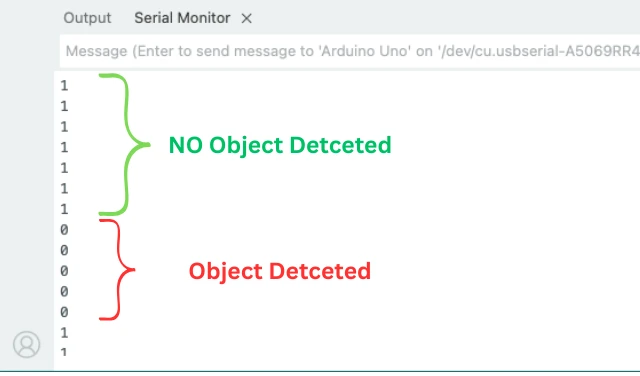
Here is what these values mean:
| Serial Output | Meaning |
|---|---|
| 1 | No object detected |
| 0 | Object detected |
If the output is not changing:
- Adjust the sensitivity potentiometer
- Bring your hand closer to the sensor
- Check wiring again
IR Sensor Arduino Code: All Modes & LCD Output
Digital Detection Mode
In digital mode, the IR sensor sends HIGH or LOW depending on whether an object is detected. This mode is simple and ideal for projects like line-following robots, obstacle detection, or counters. In this section, we will test the sensor with Arduino and understand how to read its digital output.
Object Detection Code with LED Feedback
Here’s a complete Arduino sketch to read the digital output of the IR sensor:
int irPin = 2;  // Connect IR sensor digital output to Arduino pin 2
int ledPin = 13; // Onboard LED for visual feedback

void setup() {
  pinMode(irPin, INPUT);
  pinMode(ledPin, OUTPUT);
  Serial.begin(9600);
}

void loop() {
  int sensorState = digitalRead(irPin);

  if(sensorState == LOW) { // Object detected
    digitalWrite(ledPin, HIGH);
    Serial.println("Object Detected!");
  } else { // No object
    digitalWrite(ledPin, LOW);
    Serial.println("No Object");
  }

  delay(200);
}Explanation of the Code
irPinreads the sensor’s digital output.ledPinturns on the Arduino onboard LED when an object is detected.- In the
loop(),digitalRead()checks the sensor. - If the output is LOW, it means an object is detected. The LED turns ON, and a message prints to Serial Monitor.
- If the output is HIGH, no object is detected. The LED turns OFF.
delay(200)slows down the printing for easier reading.
This setup helps you visually and digitally confirm the sensor’s detection.
Serial Monitor Output Explained
The GIF below shows the working in motion. When the object is detected, the LED on Arduino turns ON and the respective message is printed in the serial console as well.

Analog Distance Mode
Some IR sensor modules provide an analog output, giving a varying voltage based on how close an object is. This allows you to measure distances more precisely compared to digital mode. In this section, we will connect the analog output to Arduino, read the values, and understand what they mean.
Wiring for Analog Output
For analog reading, connect the IR sensor module as follows:
| IR Sensor Pin | Arduino Pin |
|---|---|
| VCC | 5V |
| GND | GND |
| AO (Analog Out) | A0 |
| DO (optional) | Not used |
Note:
If your module has both digital (DO) and analog (AO) pins, you can leave the digital pin disconnected when reading analog values.
Analog Read Code & Output
Upload this sketch to your Arduino:
int irPin = A0;  // Connect IR sensor analog output to Arduino A0

void setup() {
  Serial.begin(9600);
}

void loop() {
  int sensorValue = analogRead(irPin);
  Serial.print("Analog Value: ");
  Serial.println(sensorValue);
  delay(200);
}
Explanation of the Code
irPinis connected to the sensor’s analog output (AO).analogRead(irPin)reads values from 0 to 1023, depending on the distance of the object.- Higher values indicate that the object is closer, lower values mean the object is farther away.
Serial.println()prints the value on the Serial Monitor for observation.delay(200)slows down readings for easier monitoring.
By using analog mode, you can measure small changes in distance and use them in more advanced Arduino projects, like obstacle avoidance or automatic counters.
Display IR Readings on LCD1602 I2C
In this section, we will display the IR sensor readings on an LCD1602 I2C display. This allows you to see the output without opening the Serial Monitor. If you are new to I2C LCDs, you can follow my I2C LCD1602 Arduino Tutorial for setup and basics.
Wiring IR Sensor + LCD1602 to Arduino
The image below shows the wiring connection between IR Sensor, LCD1602 and Arduino Uno.
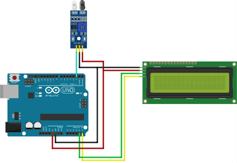
Here is the complete wiring table for both, the sensor and the LCD:
| IR Sensor Pin | Arduino Pin |
|---|---|
| VCC | 5V |
| GND | GND |
| OUT | D2 |
| LCD Pin | Arduino Pin |
|---|---|
| GND | GND |
| VCC | 5V |
| SDA | A4 (for Arduino UNO) |
| SCL | A5 (for Arduino UNO) |
Both modules work on 5V, so wiring is very simple.
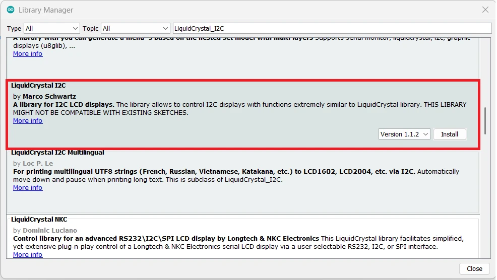
Install LiquidCrystal_I2C Library
Before writing the code, install the LiquidCrystal_I2C library:
- Open Arduino IDE.
- Go to Sketch → Include Library → Manage Libraries.
- Search for “LiquidCrystal_I2C”.
- Install the version by Frank de Brabander or Marco Schwartz.
Digital Output on LCD1602
Here is an example to show digital detection on the LCD:
#include <Wire.h>
#include <LiquidCrystal_I2C.h>

LiquidCrystal_I2C lcd(0x27, 16, 2); // I2C address 0x27, 16x2 LCD

int irPin = 2; // Digital pin connected to IR sensor

void setup() {
  pinMode(irPin, INPUT);
  lcd.init();
  lcd.backlight();
}

void loop() {
  int sensorState = digitalRead(irPin);

  lcd.clear();
  lcd.setCursor(0, 0);
  lcd.print("IR Digital State:");

  lcd.setCursor(0, 1);
  if(sensorState == LOW) {
    lcd.print("Object Detected");
  } else {
    lcd.print("No Object      ");
  }

  delay(500);
}Explanation:
lcd.clear()refreshes the display each loop.lcd.setCursor()positions text on the screen.- The first row shows the title, the second row shows object detection status.
- The LCD updates every 500ms.
Output on the LCD1602
The GIF below shows the output of the code on the LCD. When the object is detected by the sensor, the “Object Detected” is printed on the display.

Analog Output on LCD1602
For analog reading from the IR sensor:
#include <Wire.h>
#include <LiquidCrystal_I2C.h>

LiquidCrystal_I2C lcd(0x27, 16, 2); // I2C address 0x27, 16x2 LCD
int irPin = A0; // Analog output pin of IR sensor

void setup() {
  lcd.init();
  lcd.backlight();
  Serial.begin(9600);
}

void loop() {
  int sensorValue = analogRead(irPin);

  lcd.clear();
  lcd.setCursor(0, 0);
  lcd.print("IR Analog Value:");
  lcd.setCursor(0, 1);
  lcd.print(sensorValue);

  Serial.println(sensorValue); // Optional, for monitoring
  delay(500);
}Explanation:
analogRead()reads the distance value from the sensor (0–1023).- The value is displayed on the second row of the LCD.
- The first row shows a descriptive title.
Serial.println()is optional for real-time monitoring on the Serial Monitor.
This setup makes it easy to see both digital and analog IR sensor readings without needing a computer.
IR Sensor as Object Counter
IR sensors can be used for automatic counting or object detection systems.
- Place the sensor near a path where objects pass.
- Each time an object crosses, the sensor triggers a digital signal.
- Arduino can count the objects and display the count on an LCD or Serial Monitor.
Counter Code & LCD Output
Below is the code to use IR Sensor as automatic counter.
#include <Wire.h>
#include <LiquidCrystal_I2C.h>

LiquidCrystal_I2C lcd(0x27, 16, 2); // I2C address 0x27, 16x2 LCD

int irPin = 2; // Digital pin connected to IR sensor
int count = 0;

void setup() {
  pinMode(irPin, INPUT);
  lcd.init();
  lcd.backlight();
  lcd.setCursor(0, 0);
  lcd.print("Object Counter");
  lcd.setCursor(0, 1);
  lcd.print("count: ");
}

void loop() {
  if(digitalRead(irPin) == LOW) {
    while (digitalRead(irPin) == LOW);  // prevent debouncing
    count++;
  }
  lcd.setCursor(7, 1);
  lcd.print(count);
  delay(200);
}The GIF below shows the IR sensor with Arduino working as object counter.

Calibrate & Tune the IR Sensor
The IR sensor has a potentiometer that allows you to adjust its detection sensitivity. Proper adjustment ensures the sensor can detect objects accurately without false triggers. In this section, we will learn how to fine-tune the sensor and optionally use Arduino to calibrate it.
How to Use the Sensitivity Potentiometer
- Locate the small screw on the IR sensor module. This is the potentiometer.
- Turn it clockwise to increase sensitivity (sensor detects objects from farther distance).
- Turn it counterclockwise to decrease sensitivity (sensor detects objects only when closer).
- Test the sensor by moving your hand in front of it and observing the LED indicator or Serial Monitor.
IR Sensor Arduino Project Applications
Infra-Red sensors are simple, reliable, and widely used in Arduino projects. They can detect objects, measure distances, or sense motion. In this section, we will look at some of the most common and practical applications where IR sensors shine.
Line Following Robot
A line following robot uses IR sensors to detect lines on the ground, usually black lines on white surfaces.
- The IR sensor detects contrast between the line and the surface.
- Digital output helps the Arduino determine if the robot is on the line or needs to adjust its direction.
- Multiple IR sensors can be used to control left and right wheels independently.
the GIF below shows how the IR sensor can detect white lines when tuned to proper sensitivity.

Obstacle Avoidance Robot
IR sensors are often used in obstacle avoidance robots.
- The sensor detects objects in front of the robot.
- When an object is detected, the Arduino changes the robot’s path to avoid collision.
- Digital or analog readings can control turning angles or speed adjustments.
Automatic Object Counter
IR sensors can be used for automatic counting or object detection systems.
- Place the sensor near a path where objects pass.
- Each time an object crosses, the sensor triggers a digital signal.
- Arduino can count the objects and display the count on an LCD or Serial Monitor.
Below is the code to use IR Sensor as automatic counter.
#include <Wire.h>
#include <LiquidCrystal_I2C.h>

LiquidCrystal_I2C lcd(0x27, 16, 2); // I2C address 0x27, 16x2 LCD

int irPin = 2; // Digital pin connected to IR sensor
int count = 0;

void setup() {
  pinMode(irPin, INPUT);
  lcd.init();
  lcd.backlight();
  lcd.setCursor(0, 0);
  lcd.print("Object Counter");
  lcd.setCursor(0, 1);
  lcd.print("count: ");
}

void loop() {
  if(digitalRead(irPin) == LOW) {
    while (digitalRead(irPin) == LOW);  // prevent debouncing
    count++;
  }
  lcd.setCursor(7, 1);
  lcd.print(count);
  delay(200);
}
The GIF below shows the IR sensor with Arduino working as object counter.
IR Sensor Arduino — Frequently Asked Questions
Conclusion
The IR sensor is one of the best first sensors for Arduino — no library, no I2C address to scan, no pull-up resistors. Wire three pins, read one GPIO, and you have working object detection in under two minutes.
In this tutorial you covered the full range of what this module can do: reading digital HIGH/LOW for simple detection, reading the analog output for distance-proportional values, tuning sensitivity with the potentiometer, displaying both types of readings on an LCD1602 I2C display, and building an automatic object counter with a debounced interrupt-style loop. The detection GIFs show the sensor working live in each mode — line detection, obstacle sensing, and counting.
From here you can trigger relays, control motors, or combine the IR sensor with a PIR motion sensor for more sophisticated presence detection. For accurate distance measurement beyond 30 cm, step up to the HC-SR04 ultrasonic sensor or the GP2Y0A41SK0F IR distance sensor. Download the full project above and explore the Arduino Sensor Interfacing series for the next build.
Download IR Sensor Arduino Project Files
Complete Arduino project with digital detection, analog distance reading, LCD1602 I2C display sketches for both modes, and automatic object counter code. No external libraries required for sensor reading — LCD uses LiquidCrystal_I2C only. Free to download — support the work if it helped you.
Browse More Arduino Sensors Tutorials
SHT21 Arduino Tutorial: I2C Wiring, SHT2x Library, Serial & LCD Output
AHT20 Arduino Tutorial: I2C Wiring, Adafruit AHTX0 & OLED Display

SHT30 / SHT31 / SHT35 Arduino Tutorial: I2C Wiring, Code & LCD1602 Display
DS18B20 Arduino Tutorial: Single & Multiple Sensors, Serial & OLED Output
BMP180 Arduino Tutorial: I2C Wiring, Temperature, Pressure, Altitude & LCD1602

Subscribe
Login
0 Comments
Newest
