

Home ▸ Arduino ▸ Displays & Interfaces ▸
Updated On: October 25, 2026
ST7735 Arduino Tutorial: SPI Wiring, Text, Shapes and SD Card Images
The 1.8-inch ST7735 is a small color TFT display with a resolution of 128×160 pixels, and it connects to an Arduino over the SPI bus. It shows text, shapes and full-color bitmap images in 65,536 colors, which makes it a good next step for anyone who has outgrown a monochrome OLED. The Adafruit libraries handle the low-level communication, so a working screen needs only a few lines of code.
This tutorial shows how to wire the ST7735 to an Arduino Uno or Nano, install the Adafruit ST7735 and GFX libraries and confirm the setup with a test sketch. You will print text and numbers, draw lines, rectangles and circles, fill the screen with custom colors, change the screen rotation and control the backlight brightness. The last part adds an SD card on the same SPI bus and shows how to load 24-bit BMP images from it.
This display belongs to the Arduino display tutorials. If you need a smaller I2C screen, see the SSD1306 OLED tutorial or the SH1106 OLED tutorial. For a larger color screen with touch, the ILI9341 touchscreen tutorial is the natural upgrade, and the ST7920 graphic LCD tutorial covers a monochrome alternative. For number displays, see the MAX7219 and TM1637 tutorials. The SD card section builds on the SD card SPI tutorial.
Table of contents
ST7735 TFT Display Overview
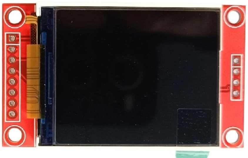
The ST7735 is the driver chip of a small TFT (thin-film transistor) color display, and the common 1.8-inch module that uses it has a resolution of 128 by 160 pixels. The driver communicates over SPI, which allows fast transfers of pixel data from the Arduino to the screen. Each pixel uses 16 bits of color, which gives 65,536 colors and is enough for text, gauges, icons and small photos.
ST7735 Specifications
| Specification | Detail |
|---|---|
| Display size | 1.8 inch, measured diagonally |
| Resolution | 128 × 160 pixels |
| Driver IC | ST7735 |
| Interface | SPI |
| Color depth | 16-bit, 65,536 colors |
| Logic level | 3.3 V |
| Supply voltage | 3.3 V, or 5 V on modules that include a regulator |
| Backlight | White LED, controlled through the BL pin |
| Extras | Many modules include a microSD card slot |
Why Use the ST7735 with Arduino
- SPI wiring needs only a few pins and works with the Uno, the Nano and the Mega.
- The 16-bit color output suits gauges, graphs, menus and icons much better than a monochrome screen.
- The Adafruit ST7735 and GFX libraries are well supported, and they use the same drawing functions as the SSD1306 OLED, so the code is easy to move between displays.
- The module is small, inexpensive and light, which suits handheld and portable projects.
The controller itself works with 3.3 V logic. Many 1.8-inch modules add a voltage regulator and resistors on the signal lines so that they can run from a 5 V Arduino, but the exact circuit depends on the seller. The wiring section explains how to check your module.
ST7735 Pinout
The pin labels vary slightly between sellers, but most 1.8-inch modules use the pins in the diagram and table below.
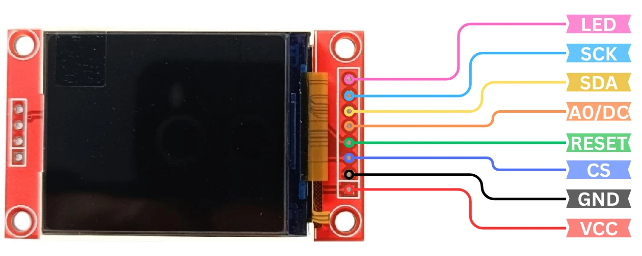
| Pin | Function | Description |
|---|---|---|
| GND | Ground | Connects to the Arduino ground |
| VCC | Power | 3.3 V, or 5 V on modules with an onboard regulator |
| SCL (CLK) | SPI clock | Synchronizes the data transfer |
| SDA (MOSI) | SPI data | Carries pixel and command data from the Arduino to the display |
| RES (RESET) | Reset | Resets the display when pulled LOW |
| DC (A0) | Data or command | LOW means the byte is a command, and HIGH means it is data |
| CS | Chip select | Enables the display while it is LOW |
| BL (LED) | Backlight | Connect to 3.3 V for constant light, or drive it through a transistor for dimming |
Modules with an SD card slot add the pins SD_CS, SD_MISO, SD_MOSI and SD_SCK, which belong to the card and not to the display. The SD card section below uses them.
ST7735 Arduino Wiring
The display uses the hardware SPI pins of the Arduino. On the Uno and the Nano, MOSI is on pin 11, MISO is on pin 12 and SCK is on pin 13. On the Mega, they are on pins 51, 50 and 52. The Arduino UNO pinout guide and the Arduino Nano pinout guide show all SPI pins in detail.
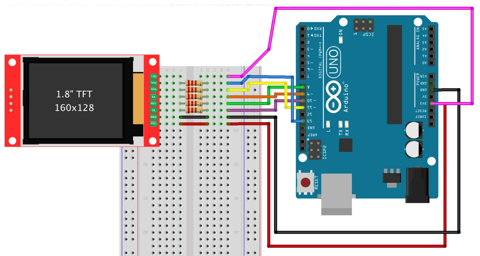
| ST7735 pin | Arduino Uno and Nano pin | Description |
|---|---|---|
| VCC | 5V or 3.3V, depending on the module | Power supply |
| GND | GND | Common ground |
| SCL (CLK) | D13 | SPI clock |
| SDA (MOSI) | D11 | SPI data from the Arduino to the display |
| RES (RESET) | D8 | Reset control |
| DC (A0) | D9 | Data or command selection |
| CS | D10 | Chip select |
| BL (LED) | 3.3V | Backlight on |
Check the Voltage Levels
An Arduino Uno outputs 5 V signals, while the ST7735 controller expects 3.3 V. Read the description of your module before you connect it.
- If the module has a regulator on VCC and a level shifter or resistor dividers on the signal lines, you can connect it directly to a 5 V board.
- If it has neither, power it from 3.3 V and place a level shifter or a resistor divider on SCK, MOSI, CS, DC and RES. A divider of 1 kΩ in series and 2 kΩ to ground works well.
- A bare backlight pin without a series resistor can draw too much current, so connect BL through a resistor of about 100 Ω unless the module already includes one.
ST7735 SPI Communication
In SPI, the Arduino is the master, and the display is the slave. Four signals do the work.
- SCL carries the clock that times each bit.
- SDA (MOSI) carries the data from the Arduino to the display.
- CS selects the display, so several SPI devices can share the same clock and data lines.
- DC tells the display whether the next byte is a command or pixel data.
The display only receives data and never sends any back, so the MISO line is not needed for the display itself. Short wires reduce noise, and a regulated 3.3 V supply gives the most stable picture. If the picture flickers or the colors break up, shorten the wires or lower the SPI speed.
ST7735 Library Setup
Two Adafruit libraries are needed. The Adafruit ST7735 and ST7789 library controls the display, and the Adafruit GFX library provides the drawing functions for text, shapes and bitmaps.
Install the Adafruit ST7735 and GFX Libraries
- Open the Arduino IDE and go to Sketch, then Include Library, then Manage Libraries.
- Search for “Adafruit ST7735” and install Adafruit ST7735 and ST7789 Library.
- Search for “Adafruit GFX Library” and install it, if the IDE did not install it together with the first library.
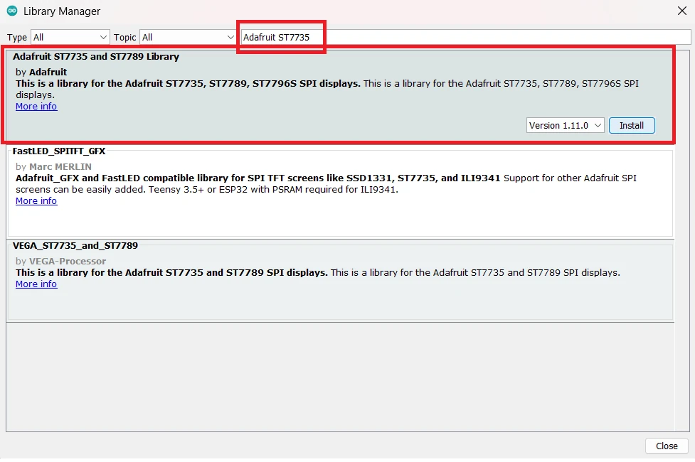
Keep both libraries up to date and use the versions from Adafruit, because older copies can cause compile errors.
ST7735 Test Sketch
A short sketch confirms that the wiring and the libraries work before you try anything larger. It sets up the display, fills the screen with black and prints a line of text.
#include <Adafruit_GFX.h>      // Core graphics library
#include <Adafruit_ST7735.h>   // ST7735 driver library
#include <SPI.h>

#define TFT_CS   10
#define TFT_DC    9
#define TFT_RST   8

Adafruit_ST7735 tft = Adafruit_ST7735(TFT_CS, TFT_DC, TFT_RST);

void setup() {
  Serial.begin(9600);

  tft.initR(INITR_BLACKTAB);   // Initialization for most 1.8-inch modules
  tft.fillScreen(ST77XX_BLACK);

  tft.setTextColor(ST77XX_WHITE);
  tft.setTextSize(2);
  tft.setCursor(10, 20);
  tft.println("ST7735 Test!");

  Serial.println("Display initialized.");
}

void loop() {
}The display should show the text “ST7735 Test!” in white on a black background.
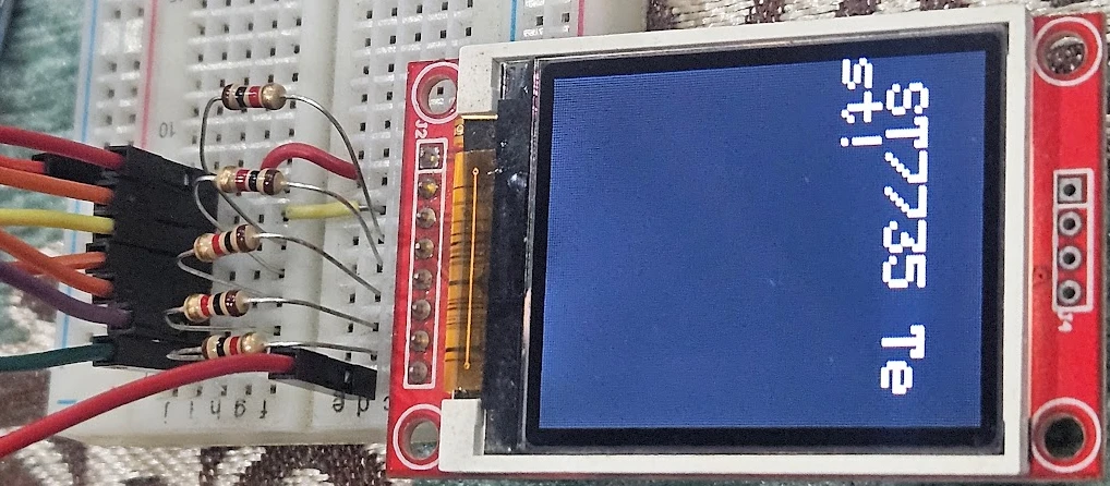
Choose the Right Initialization Tab
The initR() function takes a tab color that selects the initialization sequence for your panel. The tab color is the color of the plastic protective film on the display when it was new, and it has no relation to the colors on the screen. Most 1.8-inch modules use INITR_BLACKTAB. If the screen is blank, shifted by a few pixels, shows a noisy line at the edge or displays wrong colors, try one of the other tabs.
tft.initR(INITR_GREENTAB); // Alternatives: INITR_REDTAB, INITR_BLACKTABTry each option until the picture is correct. A 1.44-inch display with 128 by 128 pixels needs INITR_144GREENTAB in place of the tabs above.
Run the graphicstest Example
The library includes a larger test sketch that draws lines, shapes, color bars and text, so it checks the whole display. Open it from File, then Examples, then Adafruit ST7735 and ST7789 Library, then graphicstest.
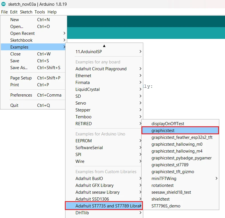
The example is written for other pins by default, so edit the top of the sketch before you upload it. Set TFT_CS to 10, TFT_RST to 8 and TFT_DC to 9, and make sure that the line tft.initR(INITR_BLACKTAB); is the active initialization line.

When the demo runs without problems, the wiring, the power and the SPI communication are all correct.
ST7735 Text and Numbers
The Adafruit GFX library prints text with the same print() and println() functions that the Serial Monitor uses. The functions below control the appearance of the text.
tft.setTextColor(color)sets the text color.tft.setTextSize(size)multiplies the size of the built-in 6 by 8 pixel font by a whole number.tft.setCursor(x, y)sets the position of the top-left corner of the next character.tft.println()prints text or a number and moves to the next line.
#include <Adafruit_GFX.h>
#include <Adafruit_ST7735.h>
#include <SPI.h>

#define TFT_CS   10
#define TFT_DC    9
#define TFT_RST   8

Adafruit_ST7735 tft = Adafruit_ST7735(TFT_CS, TFT_DC, TFT_RST);

void setup() {
  tft.initR(INITR_BLACKTAB);
  tft.fillScreen(ST77XX_BLACK);

  tft.setTextColor(ST77XX_GREEN);
  tft.setTextSize(1);
  tft.setCursor(10, 20);
  tft.println("Hello World!");

  tft.setTextColor(ST77XX_RED);
  tft.setTextSize(2);
  tft.setCursor(10, 80);
  tft.println(123.45);
}

void loop() {
}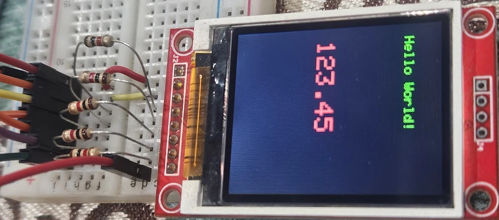
At text size 1, the screen fits 21 characters per line and 20 lines, and at size 2 it fits 10 characters per line and 10 lines.
Update Values Without Flicker
A sketch that clears the whole screen with fillScreen() before every update makes the display flicker. A better method is to give setTextColor() a second color for the background. Each character then erases the pixels behind it, and the old value disappears without a clear step.
tft.setTextColor(ST77XX_WHITE, ST77XX_BLACK);   // Text color, background color
tft.setCursor(10, 40);
tft.print(temperature, 1);
tft.print(" C "); // Trailing spaces cover a longer previous valueThis approach suits sensor readouts. The DHT11 and DHT22 tutorial, the BME280 tutorial and the MPU6050 tutorial provide values that you can print this way, and the DS3231 clock tutorial provides the time for a clock face.
ST7735 Shapes and Colors
The GFX library draws lines, rectangles and circles with a single function call each. The coordinates start at the top-left corner at (0, 0), with X growing to the right and Y growing downward.
#include <Adafruit_GFX.h>
#include <Adafruit_ST7735.h>
#include <SPI.h>

#define TFT_CS   10
#define TFT_DC    9
#define TFT_RST   8

Adafruit_ST7735 tft = Adafruit_ST7735(TFT_CS, TFT_DC, TFT_RST);

void setup() {
  tft.initR(INITR_BLACKTAB);
  tft.fillScreen(ST77XX_BLACK);

  tft.drawLine(0, 0, 127, 159, ST77XX_WHITE);   // Diagonal line
  tft.drawRect(10, 10, 60, 40, ST77XX_RED);     // Rectangle outline
  tft.fillRect(20, 20, 60, 40, ST77XX_BLUE);    // Filled rectangle
  tft.drawCircle(64, 100, 30, ST77XX_YELLOW);   // Circle outline
  tft.fillCircle(64, 100, 20, ST77XX_GREEN);    // Filled circle
}

void loop() {
}The functions take the following arguments.
drawLine(x0, y0, x1, y1, color)draws a line between two points.drawRect(x, y, width, height, color)andfillRect()draw a rectangle outline and a filled rectangle.drawCircle(x, y, radius, color)andfillCircle()draw a circle outline and a filled circle around the center point.
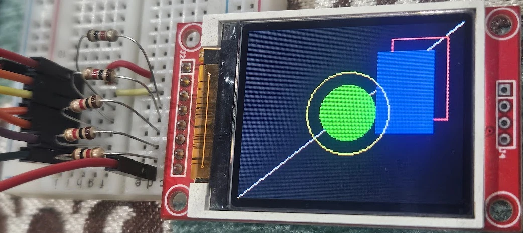
These shapes are the basis for progress bars, gauges, icons and simple charts.
Fill the Screen with a Color
The fillScreen() function fills the whole display with one color. This sketch cycles through three colors.
void loop() {
  tft.fillScreen(ST77XX_BLUE);
  delay(1000);
  tft.fillScreen(ST77XX_RED);
  delay(1000);
  tft.fillScreen(ST77XX_BLACK);
  delay(1000);
}
The library defines the color constants ST77XX_BLACK, ST77XX_WHITE, ST77XX_RED, ST77XX_GREEN, ST77XX_BLUE, ST77XX_YELLOW, ST77XX_CYAN, ST77XX_MAGENTA and ST77XX_ORANGE. Any other color comes from the color565() function, which converts red, green and blue values from 0 to 255 into the 16-bit format of the display.
uint16_t myColor = tft.color565(255, 100, 50);   // Red, green, blue
tft.fillScreen(myColor);The 16-bit format keeps 5 bits for red, 6 bits for green and 5 bits for blue, which gives 65,536 different colors.
ST7735 Rotation and Brightness
Two more settings change how the display looks in a finished project.
Rotate the Screen
The setRotation() function turns the drawing area in steps of 90 degrees. It is useful when the display is mounted sideways or upside down in an enclosure.
| Value | Orientation | Width × height |
|---|---|---|
| 0 | Portrait | 128 × 160 |
| 1 | Landscape | 160 × 128 |
| 2 | Portrait, upside down | 128 × 160 |
| 3 | Landscape, upside down | 160 × 128 |
Call tft.setRotation(1); right after tft.initR(), and use tft.width() and tft.height() in your code, so that your drawing adjusts to the new size.
Control the Backlight Brightness
The BL pin powers the backlight LED, and a PWM signal on that pin dims it. A backlight can draw more current than an Arduino pin should supply, so drive it through a small NPN transistor or a logic-level MOSFET instead of connecting it directly. Connect the transistor base through a resistor of about 1 kΩ to pin 6, and let it switch the BL line to ground or to the supply, depending on your module. If your module documentation shows that BL is a low-current logic input, a direct connection is possible.
const int backlightPin = 6;   // PWM pin

void setup() {
  pinMode(backlightPin, OUTPUT);
}

void loop() {
  for (int level = 0; level <= 255; level += 5) {
    analogWrite(backlightPin, level);   // 0 is off, 255 is full brightness
    delay(30);
  }
  for (int level = 255; level >= 0; level -= 5) {
    analogWrite(backlightPin, level);
    delay(30);
  }
}The analogWrite() function accepts values from 0 to 255, and pin 6 supports PWM on the Uno. The Arduino PWM tutorial explains the function in more detail.
ST7735 SD Card BMP Images
The display can show bitmap (BMP) images that are stored on an SD card, which suits logos, icons, menu backgrounds and small photos. The SD card uses SPI as well, so it shares the clock and the data lines with the display and needs only one extra pin for its own chip select. The SD card SPI tutorial explains the card side in more detail.
Wire the SD Card Module
Many ST7735 modules include a microSD slot with its own pins, and a separate SD module works the same way. The SD card pins connect to the same MOSI, MISO and SCK pins as the display, and the card gets a separate chip select on pin 4.
| SD card pin | Arduino pin | Description |
|---|---|---|
| VCC | 5V | Power, for modules with an onboard regulator |
| GND | GND | Common ground |
| MOSI | D11 | Shared with the display |
| MISO | D12 | Used only by the SD card |
| SCK | D13 | Shared with the display |
| CS | D4 | Chip select of the SD card |
The display keeps its own wiring from the earlier section, with CS on D10, DC on D9 and RES on D8. Each device must have its own chip select pin, and both chip select lines should be HIGH whenever a device is not in use.
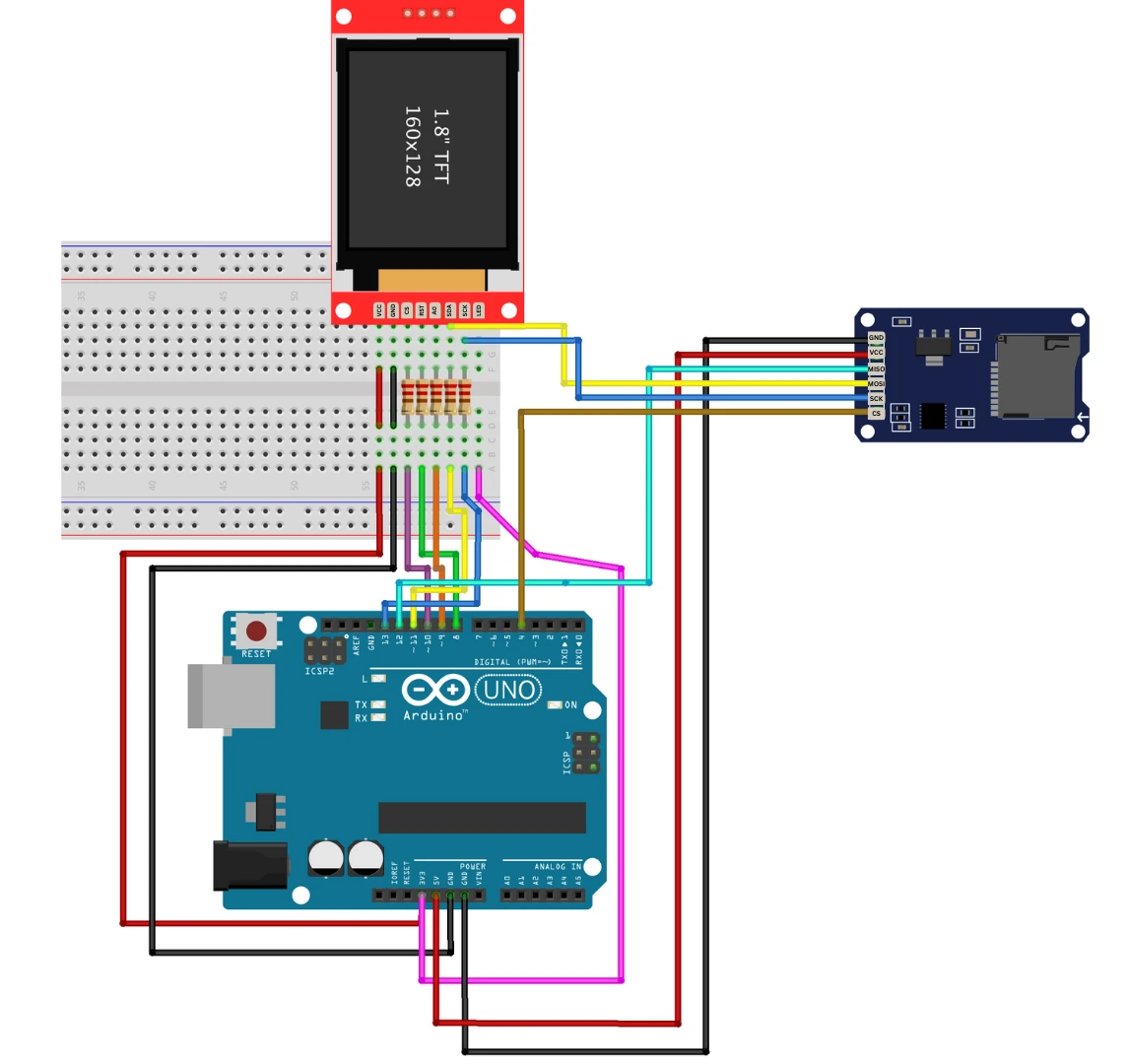
A bare SD card works at 3.3 V, so use a module with an onboard regulator and level shifters when you power it from a 5 V board.
Prepare the BMP Images
The sketch below reads uncompressed 24-bit BMP files. Prepare the card as follows.
- Format the card as FAT32, which suits cards up to 32 GB.
- Save each image as an uncompressed 24-bit BMP with a program such as Paint or GIMP. JPEG and PNG files do not work.
- Resize each image to 128 by 160 pixels or smaller. The sketch also clips images that are larger than the screen.
- Copy the files to the root folder of the card with short names, for example
image1.bmpandimage2.bmp.
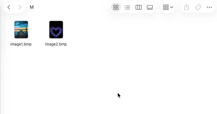
A 32-bit BMP or a file with compression does not work, because the sketch checks the bit depth and rejects such files.
BMP Display Code
The sketch below draws two images in turn. The function bmpDraw() reads the BMP header, checks the format, sets the drawing window on the display and sends the pixels row by row. BMP files store pixels in blue, green, red order and usually store the bottom row first, so the function reads the rows in reverse and swaps the color order. The helper functions read16() and read32() read little-endian numbers one byte at a time.
#include <Adafruit_GFX.h>
#include <Adafruit_ST7735.h>
#include <SPI.h>
#include <SD.h>

#define TFT_CS   10
#define TFT_DC    9
#define TFT_RST   8
#define SD_CS     4

#define BUFFPIXEL 20   // Pixels read from the card at once

Adafruit_ST7735 tft = Adafruit_ST7735(TFT_CS, TFT_DC, TFT_RST);

void setup() {
  Serial.begin(9600);

  // Keep both chip select lines HIGH before either device starts
  pinMode(TFT_CS, OUTPUT);
  digitalWrite(TFT_CS, HIGH);
  pinMode(SD_CS, OUTPUT);
  digitalWrite(SD_CS, HIGH);

  tft.initR(INITR_BLACKTAB);
  tft.fillScreen(ST77XX_BLACK);

  if (!SD.begin(SD_CS)) {
    Serial.println(F("SD card initialization failed."));
    while (true);
  }
  Serial.println(F("SD card initialized."));
}

void loop() {
  bmpDraw("image1.bmp", 0, 0);
  delay(2000);
  bmpDraw("image2.bmp", 0, 0);
  delay(2000);
}

void bmpDraw(const char *filename, int16_t x, int16_t y) {
  File bmpFile;
  uint8_t sdbuffer[3 * BUFFPIXEL];
  uint8_t buffidx = sizeof(sdbuffer);
  bool flip = true;   // BMP rows are stored bottom to top

  if ((x >= tft.width()) || (y >= tft.height())) return;

  bmpFile = SD.open(filename);
  if (!bmpFile) {
    Serial.print(F("File not found: "));
    Serial.println(filename);
    return;
  }

  if (read16(bmpFile) != 0x4D42) {          // "BM" signature
    Serial.println(F("Not a BMP file."));
    bmpFile.close();
    return;
  }

  read32(bmpFile);                          // File size
  read32(bmpFile);                          // Reserved
  uint32_t imageOffset = read32(bmpFile);   // Start of the pixel data
  read32(bmpFile);                          // Header size
  int32_t bmpWidth  = read32(bmpFile);
  int32_t bmpHeight = read32(bmpFile);

  // Planes must be 1, depth must be 24 bits, compression must be 0
  if (read16(bmpFile) != 1 || read16(bmpFile) != 24 || read32(bmpFile) != 0) {
    Serial.println(F("Use an uncompressed 24-bit BMP."));
    bmpFile.close();
    return;
  }

  uint32_t rowSize = (bmpWidth * 3 + 3) & ~3;   // Rows are padded to 4 bytes
  if (bmpHeight < 0) {                          // Negative height: top to bottom
    bmpHeight = -bmpHeight;
    flip = false;
  }

  // Clip the image to the screen
  int16_t w = bmpWidth;
  int16_t h = bmpHeight;
  if ((x + w - 1) >= tft.width())  w = tft.width()  - x;
  if ((y + h - 1) >= tft.height()) h = tft.height() - y;

  tft.setAddrWindow(x, y, w, h);   // Position, width and height

  for (int16_t row = 0; row < h; row++) {
    uint32_t pos = imageOffset + (flip ? (bmpHeight - 1 - row) : row) * rowSize;

    if (bmpFile.position() != pos) {    // Jump to the start of the row
      bmpFile.seek(pos);
      buffidx = sizeof(sdbuffer);       // Force a new read
    }

    for (int16_t col = 0; col < w; col++) {
      if (buffidx >= sizeof(sdbuffer)) {
        bmpFile.read(sdbuffer, sizeof(sdbuffer));
        buffidx = 0;
      }
      uint8_t b = sdbuffer[buffidx++];
      uint8_t g = sdbuffer[buffidx++];
      uint8_t r = sdbuffer[buffidx++];
      tft.pushColor(tft.color565(r, g, b));
    }
  }

  bmpFile.close();
}

uint16_t read16(File &f) {
  uint16_t low  = f.read();
  uint16_t high = f.read();
  return (high << 8) | low;
}

uint32_t read32(File &f) {
  uint32_t b0 = f.read();
  uint32_t b1 = f.read();
  uint32_t b2 = f.read();
  uint32_t b3 = f.read();
  return b0 | (b1 << 8) | (b2 << 16) | (b3 << 24);
}The two images alternate every two seconds. The setAddrWindow() function of the current Adafruit library takes the position, the width and the height of the window, and older code examples that pass the end coordinates instead produce a shifted image. Drawing pixel by pixel is slow, so a full-screen image takes a moment to appear, which is normal for an Uno.

If an image looks mirrored or stretched, check its size and bit depth first. File names on the FAT file system are not case-sensitive in the SD library, but a short name in lowercase, such as image1.bmp, avoids surprises.
ST7735 Troubleshooting
Most ST7735 problems come from wiring, voltage levels or the initialization tab.
The Screen Stays White or Blank
Check the power, the ground and the backlight connection first. Then check that the CS, DC and RES pins match the definitions in the sketch, because a swapped pin produces a white or blank screen. If the pins are correct, try another initialization tab, as described in the test sketch section.
The Colors Are Wrong or Shifted
Red and blue swapped, inverted colors or a shifted picture with noise at one edge usually point to the wrong initialization tab. Change INITR_BLACKTAB to INITR_GREENTAB or INITR_REDTAB until the picture is correct.
SD card initialization failed
The card must be FAT32, the wiring of the SD chip select must match SD_CS, and the module must have a stable supply. The display and the SD card share the bus, so both chip select pins have to be set HIGH before SD.begin() is called, as the sketch above does. Try a second card if the problem continues, because some cards do not work in SPI mode.
The Image Is Blank or Distorted
The file is probably not a 24-bit uncompressed BMP, or it is larger than the screen. Save it again at 24 bits and resize it to 128 by 160 pixels.
The Display Resets or Flickers
A weak supply is the usual cause. The backlight and the SD card draw current together, so use a stable 5 V source and keep the wires short. A shared ground between all modules is also required.
Conclusion
This tutorial showed how to wire the ST7735 TFT to an Arduino, install the Adafruit libraries and confirm the setup with a test sketch. It also covered text, shapes, colors, rotation and backlight brightness, and how to show BMP images from an SD card.
The important points are the 3.3 V logic level of the display, the correct initialization tab for your panel and a separate chip select pin for the SD card. With these basics you can build dashboards, small game screens and image viewers.
Browse More Arduino Display Tutorials
How to Interface MAX7219 7 Segment Display with Arduino | Display Text, Scrolling Message, and Time
Arduino ST7920 Tutorial (128×64 LCD): Wiring, Setup, U8g2, and Text Display Guide
Arduino ST7920 Display Graphics Guide: Shapes, Icons, Bitmaps, and UI Design
Arduino ST7920 Graphics Guide: How to Create Scrolling Text, Animations and Page Transitions (U8g2)
ST7920 Arduino Projects Tutorial: Real-Time Graphs, Menu System, and Full Dashboard UI using U8g2
Subscribe
Login
0 Comments
Newest

