How to Send data from UART to UI
This is the 3rd tutorial in the Riverdi STM32 Display series, and today we will see how to receive the data from UART and then display it to the UI. This is going to be continuation from the previous tutorial, where we controlled the LED using the Buttons on the display. We will simply create new task to receive the UART data and a new queue to send the data to the UI.
I have already explained about the additional file in the previous tutorial, and how to modify the Makefile so as to compile this new file we created. We will skip that part in today’s tutorial .
Let’s start with modifying the GUI design in the touchGFX.
VIDEO TUTORIAL
You can check the video to see the complete explanation and working of this project.
TouchGFX Setup
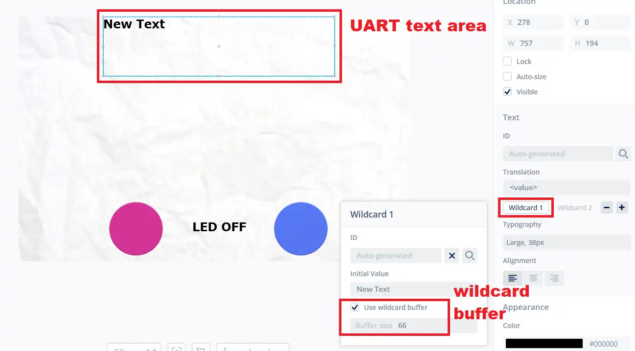
Here I have just added one more text area (textAreaUART) to display the UART data. The rest of the setup is same as the previous tutorial.
The textAreaUART uses the “large” typography and a wildcard buffer with 66 bytes. The wildcard range is already set for the “large” typography so we don’t need to make any changes there.
UART Setup
The Riverdi STM32 Display pinout allows the use of 4 different UARTs.
The USART 1 can be used normally and the pins are available in the expansion connector. While the UART 8 can be used for the modbus and only have one pin i.e. TX. The picture of the expansion connector is shown below.
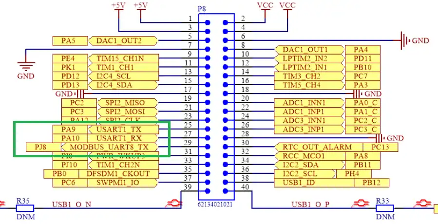
The UART2 and UART4 are connected to the RS232 and RS485 ports respectively. You would need the respective devices/converters in order to communicate using these protocols.
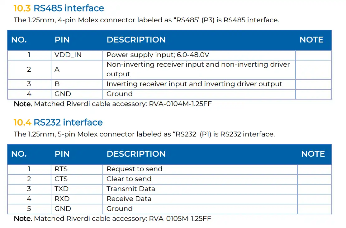
I am going to use the UART4 as I have the RS485 to USB converter, and also the connection is easier compared to others. The connection for the same is shown below.
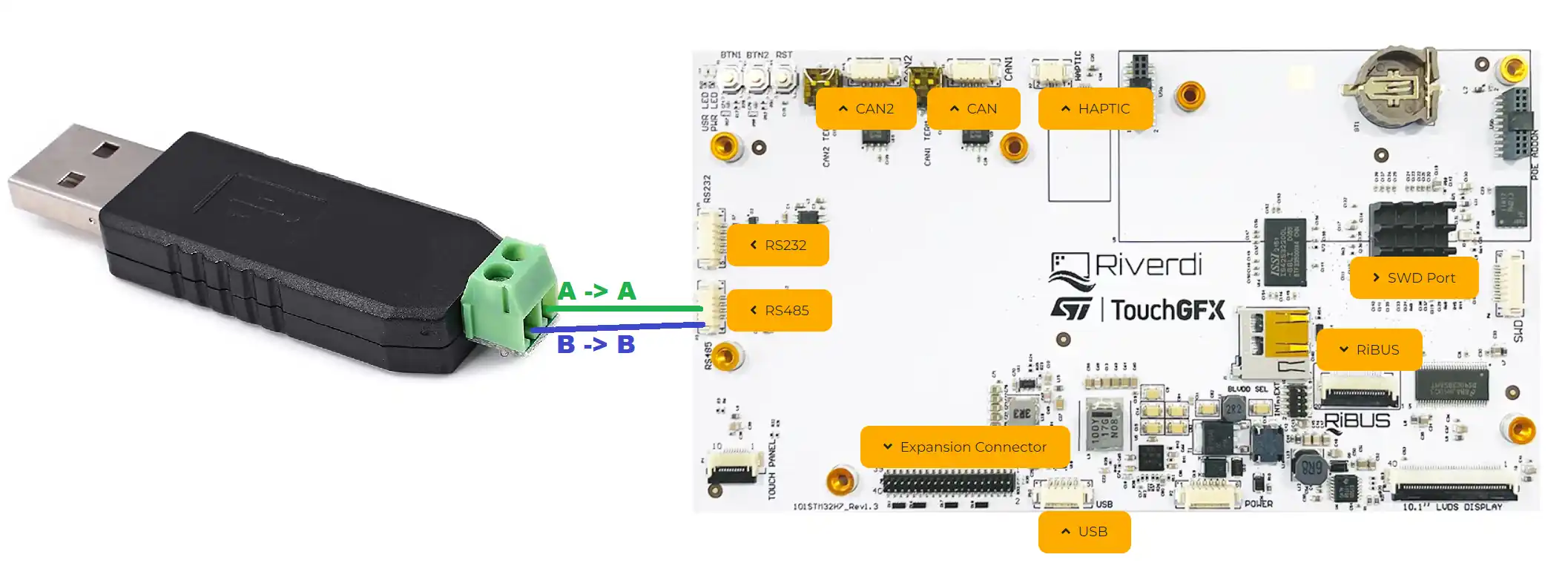
The PINA from the module is connected to the PINA of the board. And the PINB connects with PINB. This is as simple as it can be.
Now we would need to make some changes in the initialization part also. They are as follows:
The UART4 is preinitialized by the script Riverdi uses, so we don’t need to worry about it.
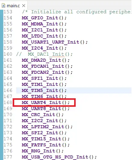
Since I want to use the IDLE Line interrupt to receive the unknown amount of data from the UART, I need to enable the Interrupt for the UART4.
To enable the interrupt, we can add the interrupt enabling functions after the initialization of the UART.
HAL_NVIC_SetPriority(UART4_IRQn, 5, 0);
HAL_NVIC_EnableIRQ(UART4_IRQn);Here the interrupt has been enabled for the UART4 with a priority of 5 (Requirement by the FreeRTOS)
Then add the interrupt handler in the interrupt source file.
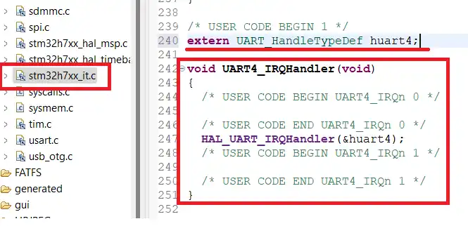
Here in the stm32h74xx_it.c file, I have defined the UART4 handle as the external variable and added the UART4 interrupt handler.
That is all the changes we need to make. Let’s see the code now
The code
In the previous tutorial, we created the myfile.c and myfile.h. We will continue with those files and write our code inside it.
myfile additions
Here we will create a task for the UART and a queue to send the data to the GUI.
osThreadId_t UARTTaskHandle;
const osThreadAttr_t UARTTask_attributes = {
.name = "UARTTask",
.stack_size = 512 * 4,
.priority = (osPriority_t) osPriorityNormal,
};
osMessageQueueId_t UARTQueueHandle;
const osMessageQueueAttr_t UARTQueue_attributes = {
.name = "UARTQueue"
};First define the Task attributes for the UART Task.
- The UARTTaskHandle is the ID of the task
- The name is UARTTask
- Stack size is 512 words
- The priority is set to normal
Next we define the Queue attributes for the UART Queue.
The UARTQueueHandle is the ID of the Queue and its name is UARTQueue.
We would need to use a structured queue to send the data array. So first define the structure in the myfile.h
typedef struct{
char data[64];
int len;
}uartdata_t;The uartdata_t has 2 elements, a character array to store the data and the length parameter to store the length of the data in the array.
void UARTTask_Init (void)
{
UARTTaskHandle = osThreadNew(StartUARTTask, NULL, &UARTTask_attributes);
}
void UARTQueue_Init (void)
{
UARTQueueHandle = osMessageQueueNew(1, sizeof(uartdata_t), &UARTQueue_attributes);
}Next we initialize the UARTTask and UARTQueue. I have created 2 separate functions for them so that we can call them in the main file.
Here StartUARTTask is the Task function, and is defined below. The queue is created with 1 element in it and the size of the element is the size of the uartdata_t structure we just defined.
void StartUARTTask(void *argument)
{
/* UART4 interrupt Init */
HAL_NVIC_SetPriority(UART4_IRQn, 5, 0);
HAL_NVIC_EnableIRQ(UART4_IRQn);
HAL_GPIO_WritePin(GPIOA, GPIO_PIN_15, GPIO_PIN_RESET);
HAL_UARTEx_ReceiveToIdle_IT(&huart4, (uint8_t *)RxData, 64);
for (;;)
{
osDelay(10000);
}
}Here i am first enabling the interrupt for the UART4. It can be done anywhere (for eg- in the main file or in the uart.c file itself) but I chose it to be here.
The pin PA15 is the DE (Driver Enable) pin. It is used to set the module (RS485 on the Riverdi board) in the transmitter or receiver mode. Since I just want to receive the data, I am setting the pin LOW so that the module can be put in the receiver mode.
Then Receive to Idle is called in the interrupt mode. It is set to receive a maximum of 64 bytes at once and the received data will be stored in the RxData buffer.
Once all the 64 bytes has been received or if it detects an IDLE line before that, an interrupt will trigger and RxEvent callback will be called.
void HAL_UARTEx_RxEventCallback(UART_HandleTypeDef *huart, uint16_t Size)
{
	strncpy(uartdata_s.data, RxData, Size);
	uartdata_s.data[Size] = '\0';
	uartdata_s.len = Size+1;
	if (osMessageQueueGetSpace(UARTQueueHandle) > 0)
	{
		osMessageQueuePut(UARTQueueHandle, &uartdata_s, 0, 0);
	}
	HAL_UARTEx_ReceiveToIdle_IT(&huart4, (uint8_t *)RxData, 64);
}- In the callback function, we will first copy the data from the RxData buffer into the data element of the structure.
- Then append a terminating character to the data in order to indicate the end of the string.
- Finally we send this structure to the UARTQueue.
- Here we will first check if there is some space in the queue.
- If there is, then we will put the message in the queue.
- Call the function receive to Idle again to re-enable the interrupt.
Main file
In the main file, we will initialize the LED Task and the LED Queue.
  /* Init scheduler */
  osKernelInitialize();  /* Call init function for freertos objects (in freertos.c) */
  MX_FREERTOS_Init();

  LEDTask_Init();  // added function
  LEDQueue_Init();  // added function
  UARTTask_Init();  // added function
  UARTQueue_Init();  // added function

  /* Start scheduler */
osKernelStart();Here the UART task and UART queue has also been added for the initialization along with the LED Task and LED Queue.
GUI Code
The Model has a tick() function which is called every time the frame refreshes on the LCD. For a 60fps display, it would be called 60 times in a second. We will add the code to read the data from the queue inside this tick() function.
void Model::tick()
{
#ifndef SIMULATOR
	if (osMessageQueueGetCount(UARTQueueHandle)>0)
	{
		if (osMessageQueueGet(UARTQueueHandle, &uartdata_r, 0, 0)==osOK)
		{
			strncpy(RData, uartdata_r.data, uartdata_r.len);
			modelListener->uart_display (RData);
		}
	}
#endif
}- It will constantly look for the count in the UARTQueue. If there is some data in the queue, the count will go to 1.
- Then the data will be read and saved into the uartdata_r structure, defined at the beginning of the model file.
- The data will be then copied into the RData buffer so that we can send it to the presenter.
- Finally the function uart_display is called in the modelListener and the RData is passedas the parameter of this function.
virtual void uart_display(char *data){}We need to define the function uart_display in the modelListener, but it should have an empty implementation. This will make the modelListener to look for the same function in the Presenter.
void Screen1Presenter::uart_display (char *data)
{
	view.uart_display(data);
}In the presenter, we will again call the same function in the view. The parameter data is passed to this function, which was received from the model.
void Screen1View::uart_display (char *data)
{
	textAreaUART.setWideTextAction(touchgfx::WIDE_TEXT_WORDWRAP);
	Unicode::strncpy(textAreaUARTBuffer, data, TEXTAREAUART_SIZE);
	textAreaUART.invalidate();
}Finally in the view we write the code to display this data.
- Here we will set the wide text action to text wordwrap. This enables the word wrap for the text area.
- The copy the string from the data into the text area buffer.
- Finally invalidate the text area so the changes can take effect.
Result
The gif above shows the UART data being displayed on the GUI. Also the LED is working normally as it should.


Hello Controllerstech,
Thank you for the detailed video tutorial. I am facing an issue where I am trying to use the USART1 which is already routed to my custom board and I am trying to Tx/Rx data from the custom board. My device setup is, RiverDI 5 inch display boards expansion connector USART1 Tx/RX pins are connected directly to my custom board’s Rx/Tx pins. I am trying to utilize the USART1 init from the stm32 project, but I am unable to read or write. Also my program does not execute the Rx callback which I have set for USART1 Rx pin. Please let me know what I am doing wrong here.
I am pretty new to embedded programming though.
Best Regards
Test the UART separately using some USB to TTL module. See if you are able to transmit and receive data on the computer.