How to Control LED using Buttons
This is 2nd tutorial in the Riverdi STM32 Display series, and today we will see how to control the LED using the buttons on the display. This might seem an easy topic to cover, but we will use a much standard approach to do so.
We will use the same method to interface different things, eg- UART, I2C, ADC etc in the future tutorials.
In today’s tutorial we will use a LED task, which will be responsible for setting the state of the LED, and an integer queue, which will be used to send the state of the button to the LED Task.
Let’s start with setting up the TouchGFX
VIDEO TUTORIAL
You can check the video to see the complete explanation and working of this project.
TouchGFX Setup
Below is the picture of the touchGFX GUI design.
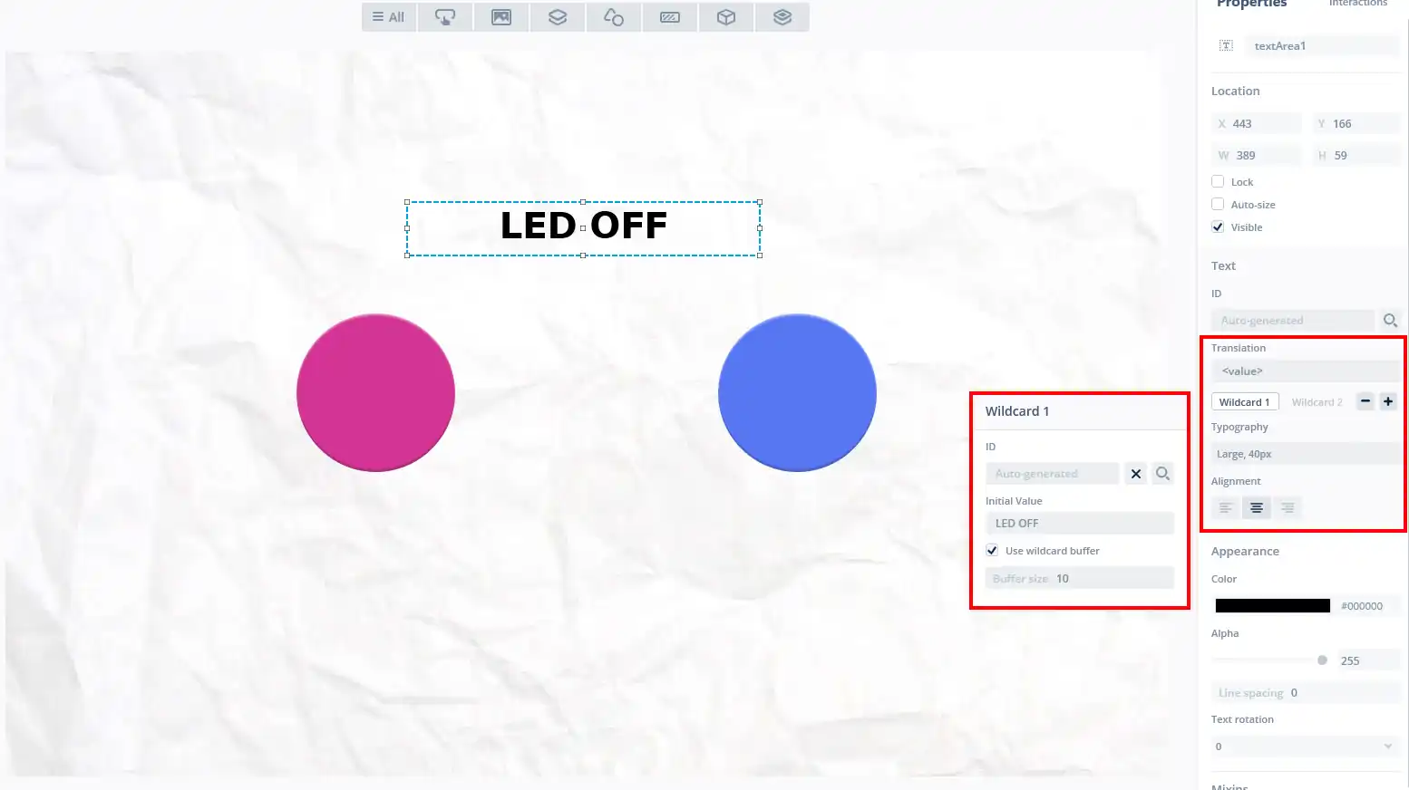
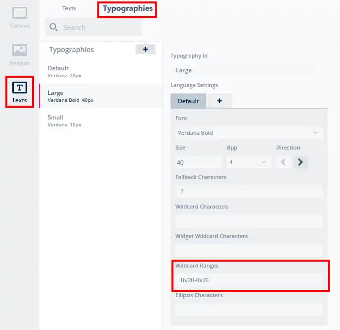
I have added 2 buttons (for ON and OFF) and a text area to display the current status of the LED. I am using large typography for the text area along with the wildcard with 10 bytes of buffer space.
The typography setup and the wildcard range is shown below.
There are 2 interactions added to the screen as shown below.
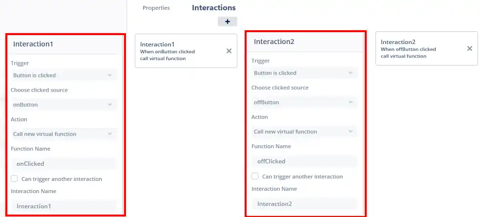
- When the onButton is pressed, the onClicked function will be called, which we will write later in the IDE.
- Similarly if the offButton is pressed, the offClicked function will be called.
Additional Setup
We will write our code in a separate file. This way, whenever needed, we only have to make changes in that particular file. Let’s see how to create a new source file for our code.
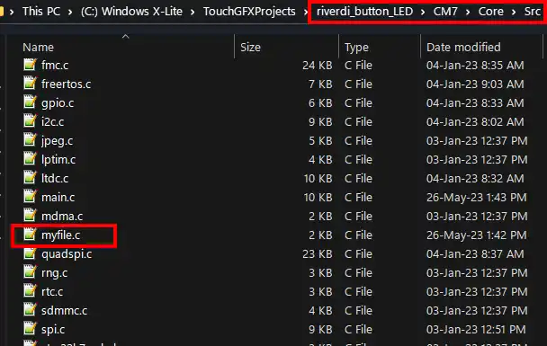
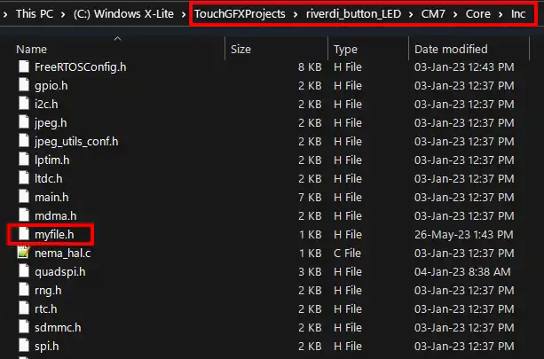
Go to ProjectFolder->CM7->core->src and create a ***.c file here. Also create a ****.h file in the ProjectFolder->CM7->core->inc. I have created myfile.c and myfile.h as shown below
Now we need to add the source file we created in the makefile for compilation.
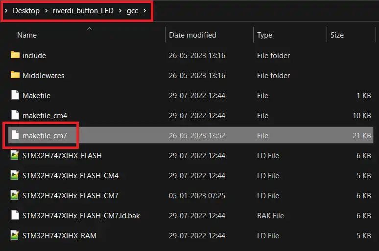
Go to ProjetFolder->gcc and open the makefile_cm7 for editing.
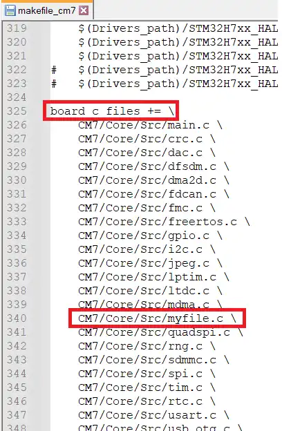
Now scroll down till you see the “board_c_files”. Here add the path to the file you just created.
That’s all the setup we need. Now we will write our code in the source file we just created.
To see the design process in more details, check out the video at the end of the post.
The code
main file
I have attached a LED to the pin PA5 on the expansion connector.
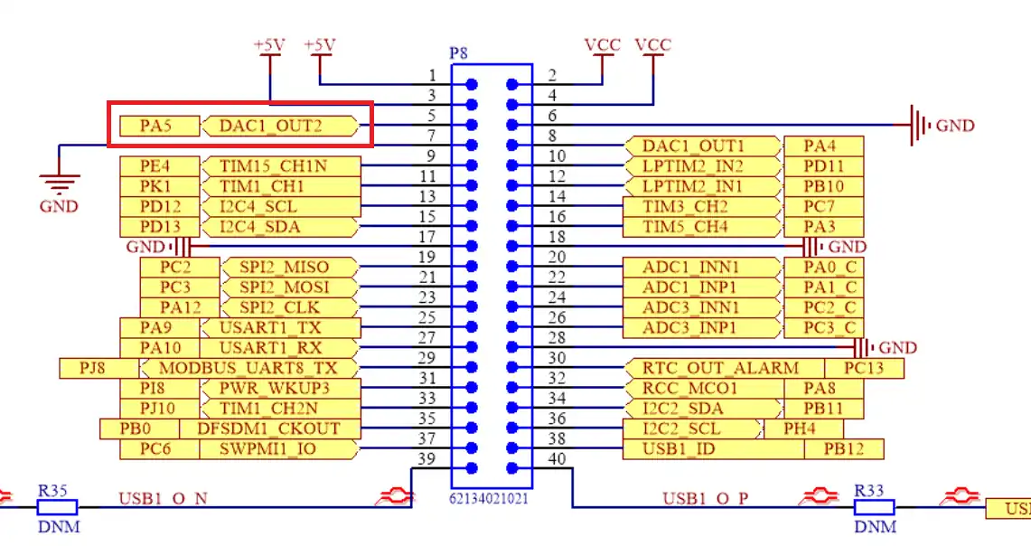
By default this pin is set as the DAC output pin, so we need to set it as the IO pin for the LED to work.
  /* Initialize all configured peripherals */
  MX_GPIO_Init();
  MX_MDMA_Init();
  MX_USART1_UART_Init();
  MX_I2C4_Init();
//  MX_DAC1_Init();
  MX_DMA2D_Init();
  MX_FDCAN1_Init();
  MX_FDCAN2_Init();
.....
.....
LED_Init();In the main function I have commented out the initialization of the DAC and instead initialized the LED with LED_Init() function. This function initializes the LED in the output mode as shown below.
void LED_Init (void)
{
	HAL_GPIO_WritePin(GPIOA, GPIO_PIN_5, GPIO_PIN_RESET);
	GPIO_InitTypeDef GPIO_InitStruct = {0};
	GPIO_InitStruct.Pin = GPIO_PIN_5;
	GPIO_InitStruct.Mode = GPIO_MODE_OUTPUT_PP;
	GPIO_InitStruct.Pull = GPIO_NOPULL;
	GPIO_InitStruct.Speed = GPIO_SPEED_FREQ_LOW;
	HAL_GPIO_Init(GPIOA, &GPIO_InitStruct);
}myfile
Now let’s write the myfile.c that we created earlier.
Here we will create a task to set the LED state and a queue to receive the data from the GUI.
osThreadId_t LEDTaskHandle;
const osThreadAttr_t LEDTask_attributes = {
  .name = "LEDTask",
  .stack_size = 512 * 4,
  .priority = (osPriority_t) osPriorityNormal,
};We will first define the Task attributes for the LED Task.
- The LEDTaskHandle is the ID of the task
- The name is LEDTask
- Stack size is 512 words
- The priority is set to normal
osMessageQueueId_t LEDQueueHandle;
const osMessageQueueAttr_t LEDQueue_attributes = {
		.name = "LEDQueue"
};Next we define the Queue attributes for the LED Queue.
The LEDQueueHandle is the ID of the Queue and its name is LEDQueue.
void LEDTask_Init (void)
{
	LEDTaskHandle = osThreadNew(StartLEDTask, NULL, &LEDTask_attributes);
}

void LEDQueue_Init (void)
{
	LEDQueueHandle = osMessageQueueNew(1, sizeof(int), &LEDQueue_attributes);
}Next we initialize the LEDTask and LEDQueue. I have created 2 separate functions for them so that we can call them in the main file.
Here StartLEDTask is the Task function, and is defined below. The queue is created with 1 element in it and the size of the element is the size of the integer.
We want to transmit the state of the button via the queue, which will be wither a 1 or 0. So 1 integer element is enough for the queue.
void StartLEDTask(void *argument)
{
  int LEDState = 0;
  for(;;)
  {
     if (osMessageQueueGetCount(LEDQueueHandle) > 0)
     {
       if (osMessageQueueGet(LEDQueueHandle, &LEDState, 0, 0) == osOK)
       {
	  HAL_GPIO_WritePin(GPIOA, GPIO_PIN_5, LEDState);
       }
     }
     osDelay(10);
  }
}The LED Task retrieves the data from the queue and set the LED state as per the data.
- We will first check if the queue has some data in it.
- If it does, then we will copy the data into the LEDState variable.
- The the LED will be set or reset based on the data in the LEDState variable.
- The task will run every 10ms, but the LED will only set when the button is pressed on the GUI.
Main file
In the main file, we will initialize the LED Task and the LED Queue.
  /* Init scheduler */
  osKernelInitialize();  /* Call init function for freertos objects (in freertos.c) */
  MX_FREERTOS_Init();

  LEDTask_Init();  // added function
  LEDQueue_Init();  // added function

  /* Start scheduler */
osKernelStart();Here I have added the initialization functions before the kernel starts.
GUI Code
We will start with the screen view file first.
void Screen1View::onClicked()
{
	presenter->LED_Control (true);
	Unicode::strncpy(textArea1Buffer, "LED ON", TEXTAREA1_SIZE);
	textArea1.invalidate();
}

void Screen1View::offClicked()
{
	presenter->LED_Control (false);
	Unicode::strncpy(textArea1Buffer, "LED OFF", TEXTAREA1_SIZE);
	textArea1.invalidate();
}We defined the interactions in the GUI so that the onClicked and offClicked functions will be called respectively, when the onButton and offButton are pressed.
- When the onButton is clicked, we will call the function LED_Control in the presenter and pass the parameter true.
- Then we will set the LED state in the TextArea and invalidate it for the changes to take effect.
- Similarly when the offClicked function is called, we pass the parameter false to the LED_Control function and set the LED state as LED OFF.
void Screen1Presenter::LED_Control(bool state)
{
	model->LED_Control(state);
}In the Screen1Presnter, when the LED_Control function is called, we will call the same function in the model file and pass the state as the parameter.
#ifndef SIMULATOR
#include "cmsis_os.h"
#include "myfile.h"
extern "C"{
	extern osMessageQueueId_t LEDQueueHandle;
}
#endif
......
......
void Model::LED_Control(bool state)
{
#ifndef SIMULATOR
	if (osMessageQueueGetSpace(LEDQueueHandle) > 0)
	{
		osMessageQueuePut(LEDQueueHandle, &state, 0, 0);
	}
#endif
}In the model source file we will first define the LEDQueueHandle as the external variable. The we will finally write the LED_Control function to send the data to the queue.
- Here we will first check if there is some space in the queue.
- If there is, then we will put the message in the queue.
- The message here is the state variable, that was passed down from the presenter.
RESULT
After building the code, we will flash it from the TouchGFX. Below the gif shows the working of the buttons and the LED.


Hello tech controllers team. Do you have information on how to use the i2c communication protocol?