PWM with DMA in STM32
A while ago I explained How to use PWM in STM32. In that tutorial, we used CCR (Capture/Compare Register) to change the duty cycle of our output signal.
This works pretty well until we need to do this really fast. What I mean is, suppose you have some application where the duty cycle needs to be changes at high frequency, what happens then ?
Well we can use the same CCR Register, but the CPU time taken for this entire process will affect the output signal. Also since we need to do this really quick, we won’t be able to perform other operations on our MCU.
The solution here is obvious, the use of DMA. And that’s basically what this tutorial is about. How to use DMA to change the duty cycle in a PWM signal.
CubeMX Setup
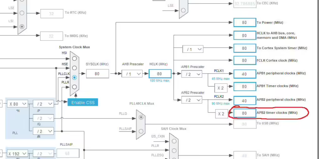
First of all Let’s see the clock setup. Notice that the APB2 Timer Clock is running at 80 MHz
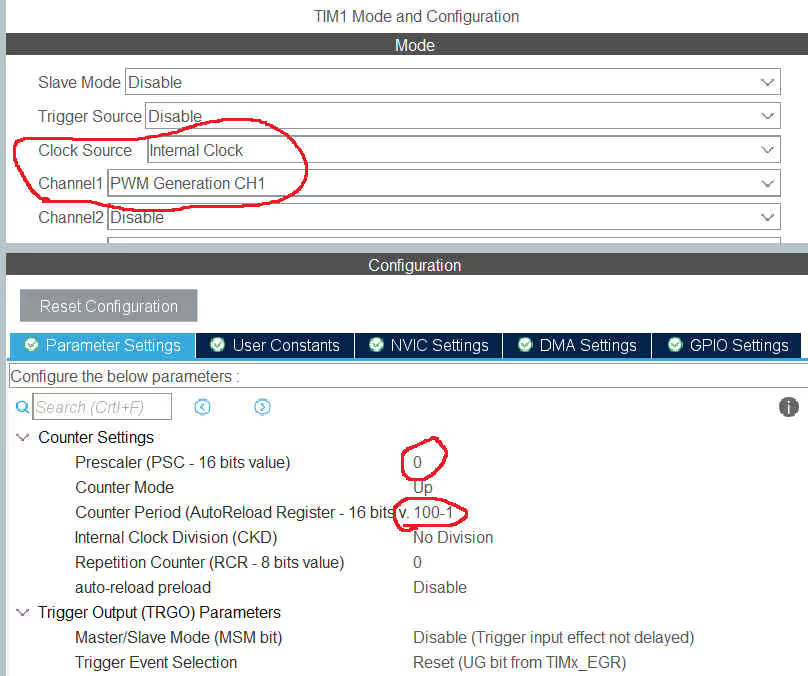
Now we will enable the Timer 1 in the PWM output mode. Also note that the Prescalar is set to 0, and ARR is 80-1
- Since the Timer 1 is connected to the APB2 clock, it was initially running at 80 MHz
- Now we use prescalar of 0, that means we are diving this Frequency by 1, So the timer is still running at same 80 MHz frequency
- The ARR of 100 will bring down this timer frequency to 80MHz/100 = 800 KHz
- Also this 100 in the ARR is the maximum duty cycle, so we have the advantage of changing duty cycle as a percentage from 100.
- For example, if we want the duty cycle of 30%, we will just use the value 30, since 100% corresponds to the value 100 in ARR
Now let’s setup the DMA
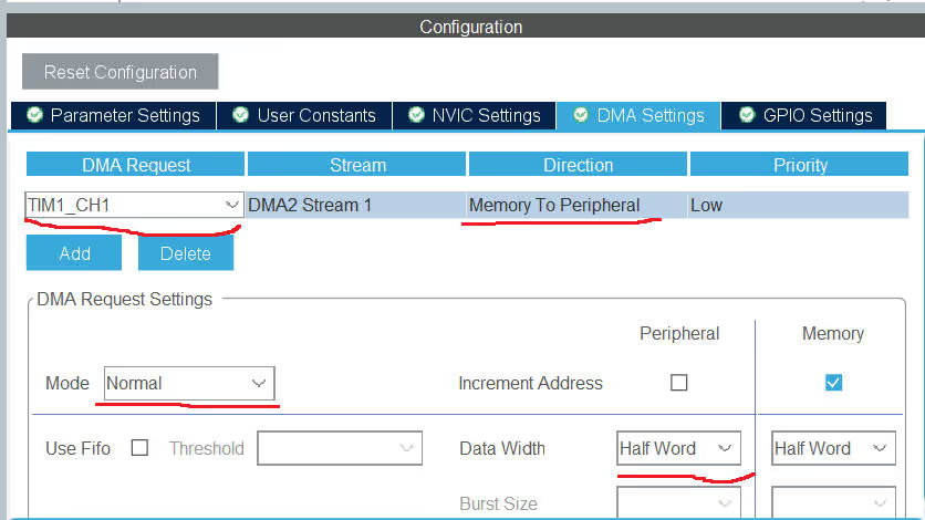
- DMA is set for TIM1 channel 1
- Memory to peripheral direction is needed, since we are sending the data to the peripheral
- Use the normal mode, since we only want the DMA to transfer the data, when we command it to do so
- I am using the data width of half word here, for no particular reason
This completes the setup process. Let’s see how to use it
Why PWM DMA ?
Here I am just taking the example from how we usually send the data to the WS2812 (NeoPixel) LED.
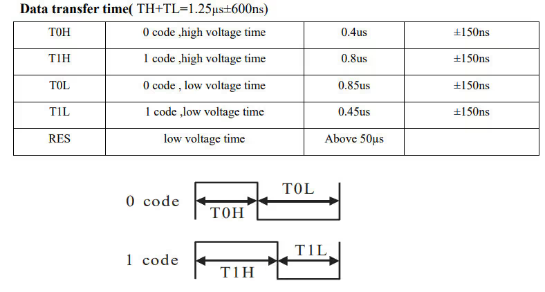
Below is the picture from the WS2812 datasheet, showing the timing for 1 and 0
As you can see above, the 1s and 0s are represented by the duty cycle of a PWM signal, whose Time Period is 1.25 us. This is the reason I chose 800 KHz frequency (1/1.25us) for the timer.
Since these devices are very sensitive to the time (in nano seconds), we can not risk using simple PWM here. We will definitely miss few bits while setting the registers manually. To avoid this, DMA is used in such scenarios.
- To send a 0, the T0H time is 0.4us, which is around 33% of 1.25 us and T0L time is 0.85 us, which comes around 67% of 1.25 us
- Similarly, in order to send a 1, we need to keep the signal HIGH for around 67% of the time
- Now remember that our ARR value is 100, which is 100% duty cycle
- That means, to send a 0 we will use 33 and to send a 1 we will use 67 in our values for the DMA buffer.
This is shown in the code below
The CODE
int datasentflag=0;

void HAL_TIM_PWM_PulseFinishedCallback(TIM_HandleTypeDef *htim)
{
	HAL_TIM_PWM_Stop_DMA(htim, TIM_CHANNEL_1);
	datasentflag = 1;
}


uint16_t pwmData[24];

void WS2812_Send (uint32_t color)
{
	for (int i=23; i>=0; i--)
	{
		if (color&(1<<i))
		{
			pwmData[i] = 66;
		}
		else pwmData[i] = 33;
	}

	HAL_TIM_PWM_Start_DMA(&htim1, TIM_CHANNEL_1, (uint32_t *)pwmData, 24);
	while (!datasentflag){};
	datasentflag = 0;
}

int main(void)
{

  HAL_Init();

  SystemClock_Config();

  MX_GPIO_Init();
  MX_DMA_Init();
  MX_TIM1_Init();

  uint32_t colour = 0x347235;  // colour code for some color
  WS2812_Send(colour);

  while (1)
  {

  }
}- Here color is the 32 bit variable, which stores 24 bit RGB color code for the LED
- Now we check every single bit of color
- if the bit is 1, the value 66 gets stored in that position
- if the bit is 0, the value 33 gets stored
- This is exactly as I mentioned in the previous heading. 66% of ARR for 1 and 33% of ARR for 0
- Note that I am storing the MSB first. This is as per the device instructions
- We now send this buffer to the DMA
- Once the data transfer is finished, the PulseFinishedCallback will be called
- Here we will stop this DMA to make sure these values are sent only once
You can see the results below
Result
- In the picture above, you can see the Time Period is 1.25 us
- A ‘1’ is sent by keeping the Pulse High for 917 us, and then keeping it low for 333 us. This comes around 73% duty cycle, which is fine (66% expected)
- A ‘0’ is sent by keeping the Pulse High for 458 us, and then keeping it low for 792 us. This comes around 36% duty cycle (33% expected)
- This is the PWM Data signal
- The code for the Green (MSB) is sent first
- If you look at the data from right, it is 0x347235. Which is exactly what the color code was
This is it for the PWM DMA. In the Next tutorial, I will cover the WS2812 LED, which will be based on PWM DMA.


Hi. Do you just use HAL_TIM_PWM_PulseFinishedCallback like that or do you have to activate some interruption? Because I have been trying to use but I just can’t make it work.
DMA interrupt is automatically enabled when you configure the DMA. But do make sure that it is enabled in the NVIC Tab of the timer.
DMA interrupt is automatically enabled when you configure the DMA. But do make sure that it is enabled in the NVIC Tab of the timer.
Hi. Just one question. Do you just use HAL_TIM_PWM_PulseFinishedCallback lke that, or do you have to activate some interruption for the timer. I have been trying to use it but I just cańt.make it work.
Hello,
Thank you very much for your expanation. It’s very helpful guide.
Hello,
I am trying this with 8MHz clock for Bluepill and Set ARR=10-1. Am not able to get the output. Any help?
Nice work. I’d choose a UART to do this job for me: Send a byte with more 1s in it for a longer pulse, less 1s in it for a shorter pulse
on an STM32F407
Tim1 is 16bit so DMA transfer needs to be half word
eg Tim2 is 32bit so use word
Thank you for this very helpful guide. If anyone else is forced by their pinout to use one of the complementary PWM outputs (e.g. CH3N) then be sure to change the call to
HAL_TIM_PWM_Start_DMA()forHAL_TIMEx_PWMN_Start_DMA()hi, do you have same example code?
HAL_TIMEx_PWMN_Start_DMA()was a very good hint. But i just get one spike out of it and no bit pattern. I’m not sure how exactly i have to configure cubeMX
That is incredible usefull! Can we see a similar tutorial for pwm with dma using STL libraries instead of HAL?