How to use Ethernet with Riverdi STM32 Displays
In the past I have covered various STM32 Embedded displays from Riverdi. One request that I always used to get about these displays is implementing the Ethernet on these displays.
So today’s tutorial will cover how to implement the Ethernet on the 7″ STM32 H7 based Riverdi display. I will use the Riverdi POE (Power Over Ethernet) Add-on to add the ethernet connectivity to the display. You can check out the product on the Riverdi website.
I am going to use the LVGL as it is easier to regenerate the project from cubeMX. I will use the SquareLine Studio to build the UI and then use it in combination with the Ethernet. To demonstrate the Ethernet application, I will create an UDP Server on the Riverdi board and then use the computer to connect and communicate to this server.
I have already covered the LVGL on the STM32H7 Riverdi display in the Previous tutorial. Anyway in this tutorial I will start from the beginning.
VIDEO TUTORIAL
You can check the video to see the complete explanation and working of this project.
Implement the LVGL
Riverdi has released some Repositories containing the LVGL implementation on its different displays. We will download the one for the 7″ display from their github https://github.com/riverdi/riverdi-70-stm32h7-lvgl. We also need to download the LVGL version 8.3 from https://github.com/lvgl/lvgl/tree/release/v8.3.
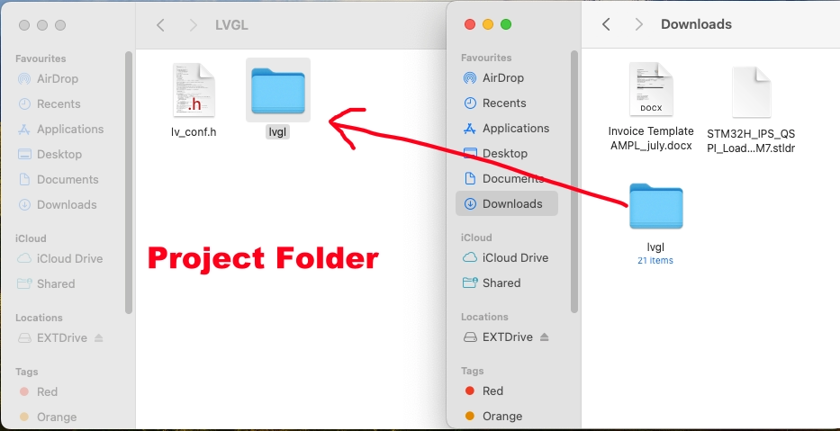
The lvgl directory in the project is located in the Project Folder -> Middleware -> Third_Party -> LVGL, but it is empty. We need to copy the lvgl directory we downloaded to this location.
Make sure to rename the downloaded lvgl_8.3 directory to “lvgl” before copying.
Now we will import the project in the cube IDE. The project structure is shown below.
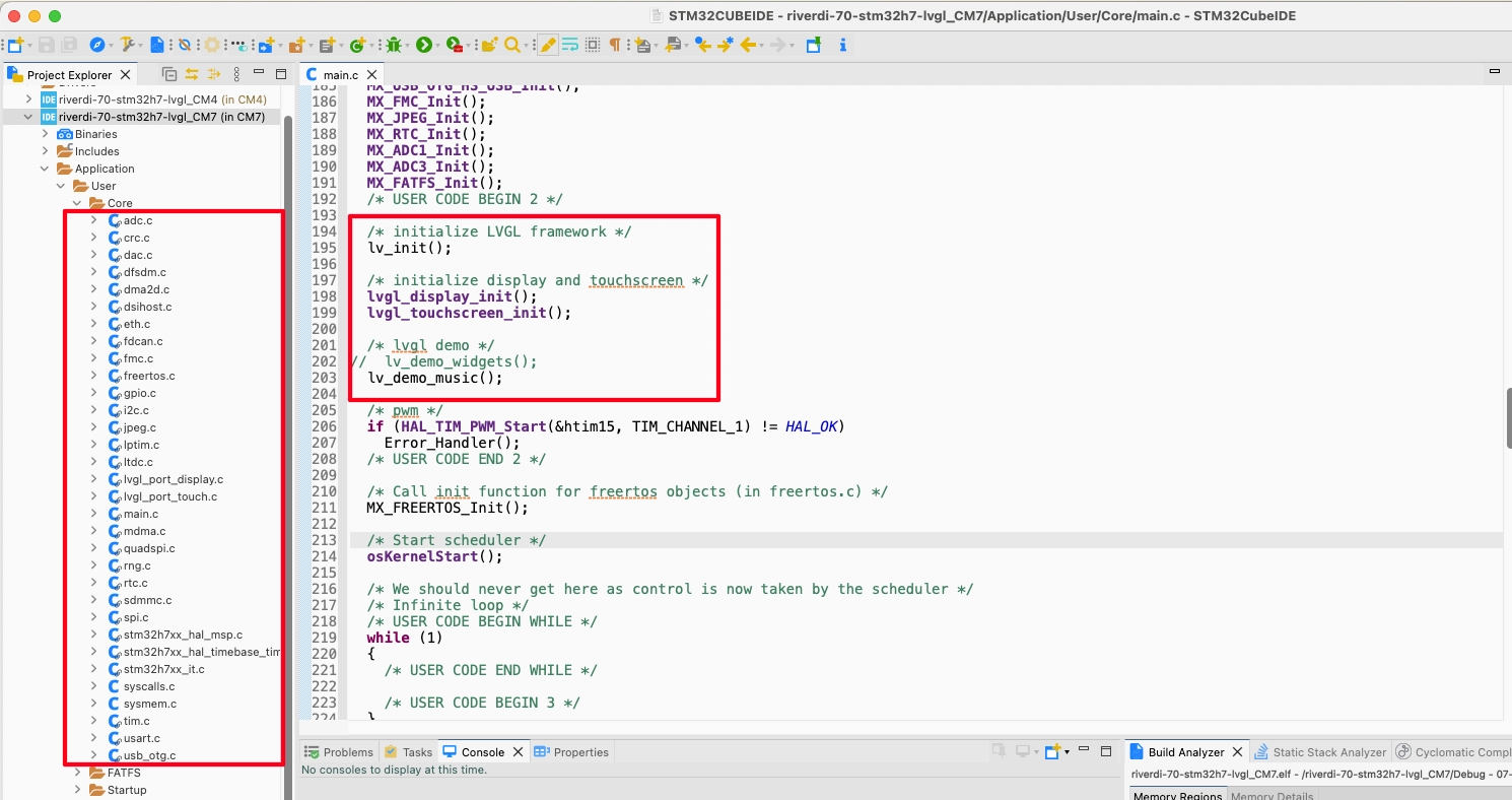
As you can see just like the other Riverdi projects we have seen, here also all the peripherals are pre-initialised. In the main file after all the initialisation is finished, the LVGL initialisation begins.
I haven’t modified anything yet and this is the default setup we get in the project. The lvgl music demo is being initialised in the default project. When we will load the default project to the board we should see the music demo playing.
Build the code does result in few warning, but there is no error. Although there is no Debug/Run configuration provided in the default project. So we need to create a new configuration to flash the project to the board.
Click on Run -> Run Configuration.
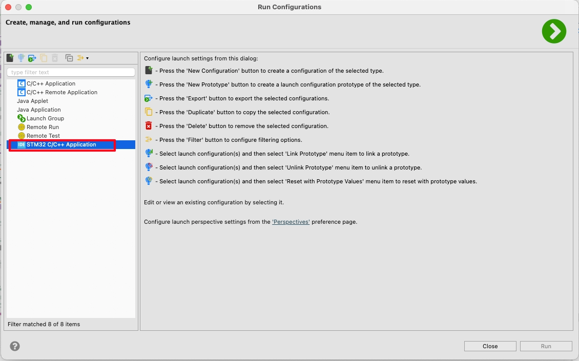
You can see in the above picture that there is no configuration present in the project. Double click on STM32 C/C++ Application to create a new configuration.
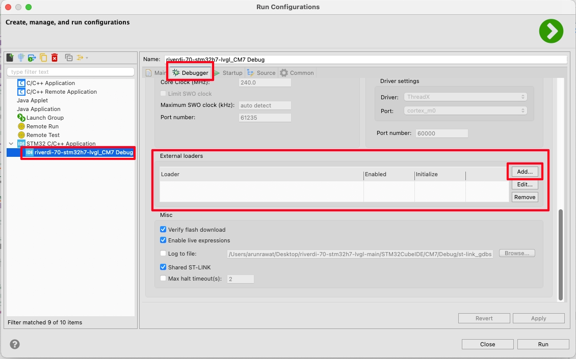
Click on the generated configuration, go to Debugger tab and scroll down to External Loader. Here you can see that the external loader is not present in the configuration. Actually the same MCU (STM32H757XIH86) is used across the 10.1″ and 7″ displays with the same QuadSPI memory. So we can use the same External Loader for all these displays.
You can download the loader from https://drive.google.com/file/d/1gUB85dc3E_Zvk4OEqkr0zDT_mvIauKXg/view?usp=sharing. Copy it inside the project folder.
Now click on add button and locate the loader.
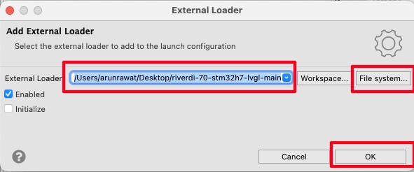
Once the loader is located, click OK. Then click Run to flash the project to the board with this configuration.
Below is the gif showing the music demo on the display.

So we have implemented the LVGL on the Riverdi 7″ STM32-H7 based display. Now we will build some UI and use it in a practical way.
CubeMX Setup
Ethernet
The Ethernet is already enabled for the M7 core by default.
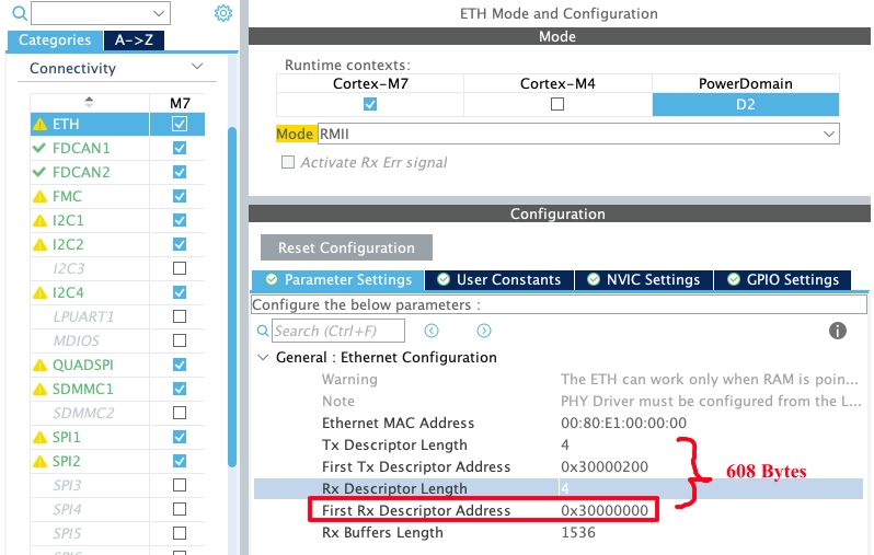
The DMA Descriptors starts at the address 0x30000000, and together they occupy 608 bytes, i.e. 0x200 + 4×24. Here 0x200 is the offset for the TX Descriptor, 4 is the length of the descriptor and 24 bytes are occupied by each descriptor.
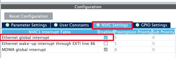
We will need to enable the Ethernet global interrupt as shown below.
LWIP
Now enable the LWIP for cortex M7. The configuration is shown below. I will only show the parameters that have been modified.
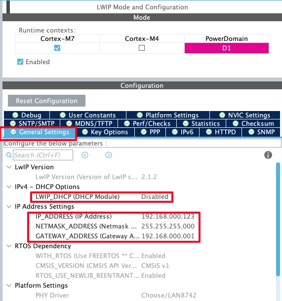
I have disabled the DHCP and configured the static IP as shown in the image above. The IP address is set to 192.168.0.123.
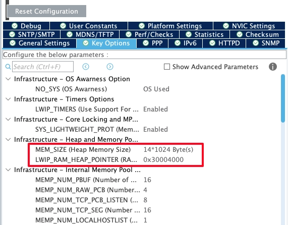
The Heap size is set to 14KB and the Heap pointer is set to address 0x30004000. We will again need this info in the MPU configuration.
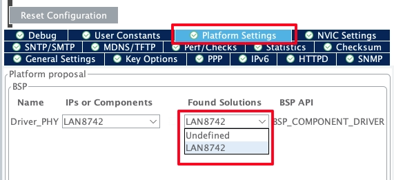
Now go to the Platform Settings and enable the LAN8742 drivers.
FreeRTOS
We also need to modify the Heap memory size in the FreeRTOS configuration.
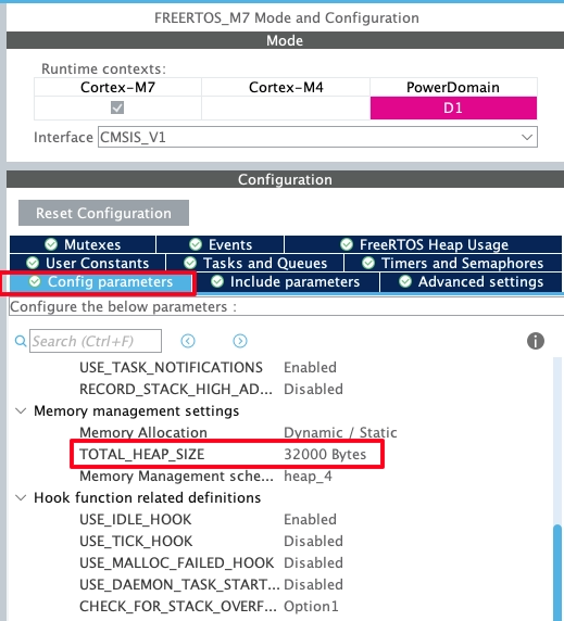
I have increased the Heap to around 32KB. We are going to create some tasks and semaphores during the runtime, so this is needed.
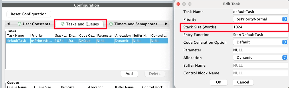
I am also increasing the Stack size for the default task to 1024.
MPU Config
We need to configure the MPU for the 2 memory regions we set above.
The DMA buffers starts at the address 0x30000000 and they occupy 608 bytes in total. Below is the MPU configuration for this region.
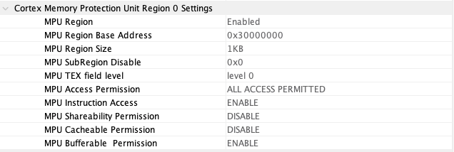
The Region Address is set to 0x30000000 with the size 1KB (>608 Bytes). Here the Instruction Access is enabled with the Bufferable Permission.
Similarly, the RAM Heap Pointer is set to address 0x30004000 and it occupies 14 KB.
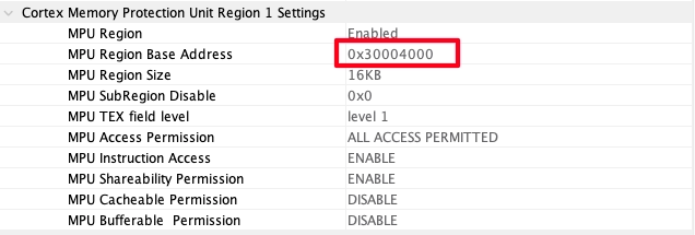
Here the Region size is set to 16 KB (>14KB) and the instruction Access is enabled along with the shareability permission.
Build UI using Squareline Studio
Click on Create, select Desktop and then select the Eclipse on PC.
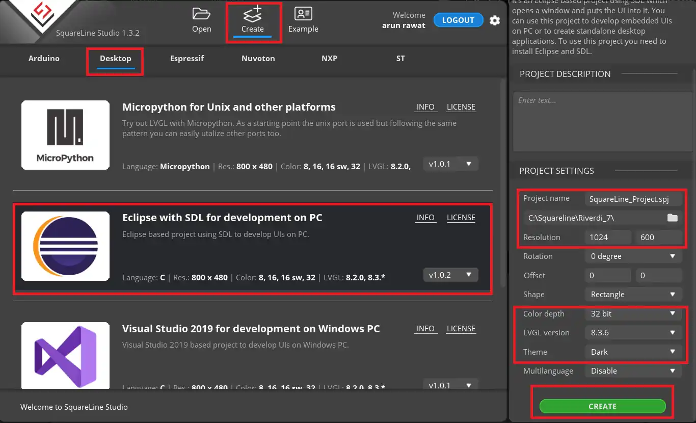
On the Right side, choose the project folder and give the project name.
- The screen Resolution is set to 1024 x 600 Pixels.
- Color depth is 32 bit.
- LVGL version is the same we downloaded, i.e 8.3.6
- I am choosing the dark theme for the screen
Click create to create the Project.
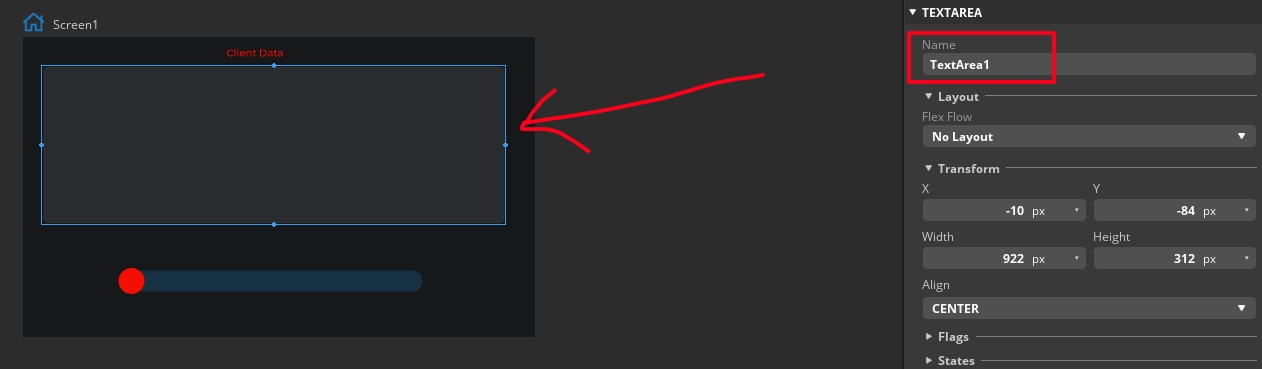
I am adding a text area to display the data sent by the client. The text area name is TextArea1.
Now add a slider to the UI.
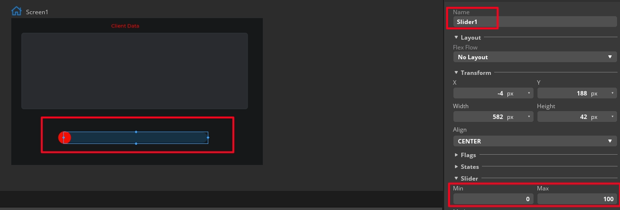
The Slider name is Slider1 and its range is set to 0 to 100.
We will also add an event to the slider which will trigger when the slider is released after the adjustment.
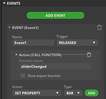
Here we will call a function, sliderChanged, which we will write in the IDE itself.
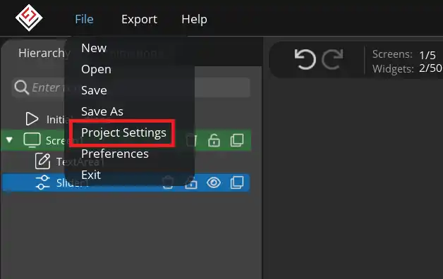
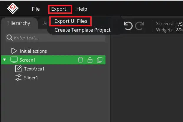
Now click on File and click Project Settings.
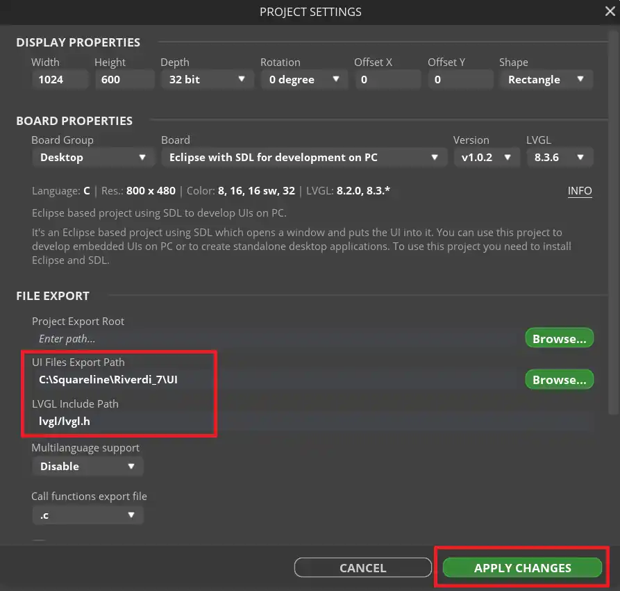
Set the UI file export path, where the exported UI files will be saved. Also set the lvgl include path to lvgl/lvgl.h.
Now click on Export and export Ui files.
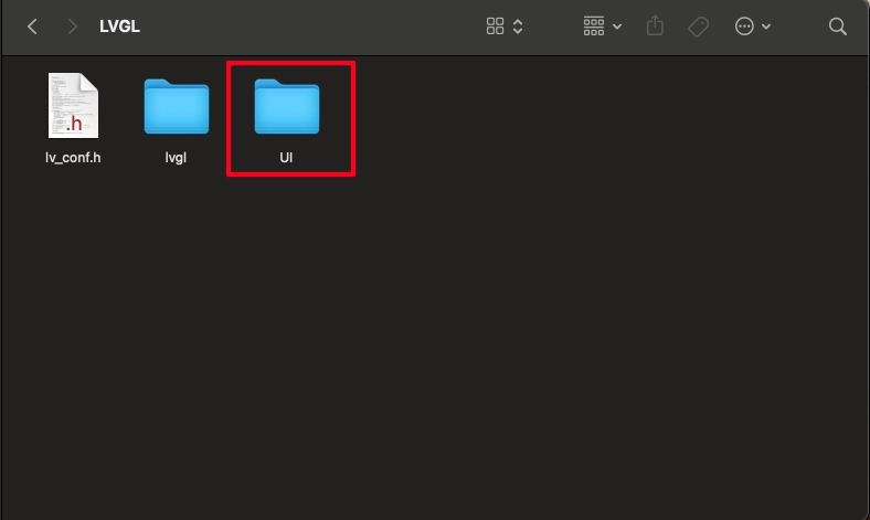
The UI files will be exported in the folder we defined earlier in the project settings. Copy this folder inside the project folder. I am copying it beside the lvgl directory.
Make Changes in the CubeIDE Project
Before we start writing the actual code, we need to add some files and define some memory locations.
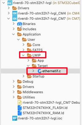
You can see below the LWIP got added to the project folder. Let’s open the ethernetif.c file.
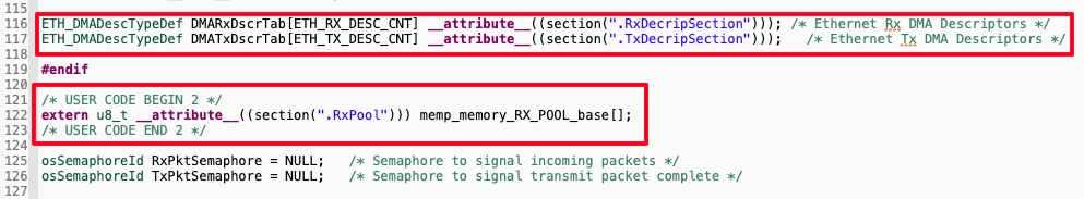
The RX and TX DMA Descriptors are defined in the ethernetif.c file. We also ned to define the RX memory pool as shown below.
The sections defined for all these buffers shall be defined in the Flash script as well. So open the STM32H747XIHX_FLASH.ld file and add the sections as shown below.
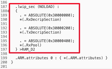
These addresses are as per the configuration we set in the cubeMX.
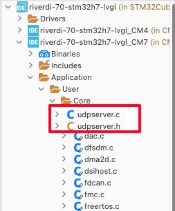
Now copy the UDPserver.c and UDPserver.h files in the Application -> User -> Core directory.
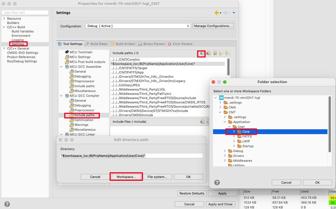
And add the Application -> User -> Core directory to the path in the project settings.
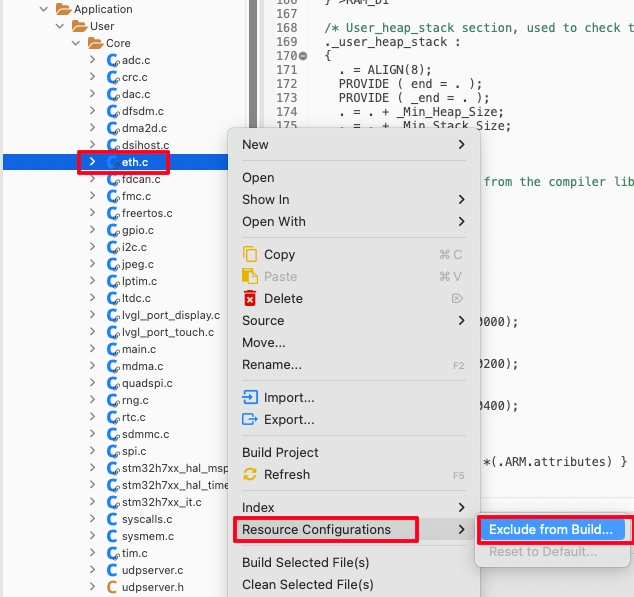
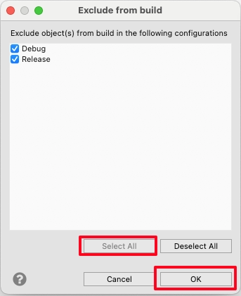
The ethernet configuration file is generated twice so we need to exclude one of them from the build configuration. This is shown below.
That is all the changes we need to make in the IDE, let’s see the code now.
The CODE
The LWIP is initialised inside the default task in the Freertos.c file. We will initialise the UDP server after the LWIP.
void StartDefaultTask(void const * argument)
{
  MX_LWIP_Init();
  udpserver_init();
  for(;;)
  {
    osDelay(1);
  }
}The udpserver_init function creates a new UDP thread. This is shown below.
void udpserver_init(void)
{
  sys_thread_new("udp_thread", udp_thread, NULL, DEFAULT_THREAD_STACKSIZE,osPriorityNormal);
}Below the code shows the UDP Thread.
static void udp_thread(void *arg)
{
	err_t err, recv_err;


	conn = netconn_new(NETCONN_UDP);

	if (conn!= NULL)
	{

		err = netconn_bind(conn, IP_ADDR_ANY, 7);

		if (err == ERR_OK)
		{
			while (1)
			{
recv_err = netconn_recv(conn, &buf);Inside the UDP thread we will create a new netconn connection and binds it to the port 7 and available IP address. Then we wait for the client to send some data.
if (recv_err == ERR_OK) // if the data is received
{
	clientaddr = netbuf_fromaddr(buf);  // get the address of the client
	clientport = netbuf_fromport(buf);  // get the Port of the client

	strncpy(msg,buf->p->payload, buf->p->len);
	lv_textarea_set_text(ui_TextArea1, msg);
	memset (msg, '\0', 100);
        netbuf_delete(buf);  // delete the netbuf
}- If the data is received from the client, we will extract client Address and Port so that it can be used later to send data to the client.
- Then copy the payload from the buffer into the msg array.
- Set the msg buffer to the text area we created in the UI.
- Now clear the msg buffer and delete the netbuf.
I have also defined another function to send the data to the client.
void udpsend (char *msg)
{
	struct pbuf *txBuf;
	int len = strlen (msg);

	/* allocate pbuf from RAM*/
	txBuf = pbuf_alloc(PBUF_TRANSPORT,len, PBUF_RAM);
	/* copy the data into the buffer  */
	pbuf_take(txBuf, msg, len);
	// refer the nebuf->pbuf to our pbuf
	buf->p = txBuf;

	netconn_connect(conn, clientaddr, clientport);  // connect to the destination address and port
	netconn_send(conn,buf);  // send the netbuf to the client
}The udpsend function takes the character pointer as the parameter.
- Here we will first allocate the pbuf of the required size.
- Then copy the data into the pbuf, and refer it to the netbuf.
- Connect to the client with the address and Port we stored earlier and send the data to the client.
When the slider is released after the adjustment, the sliderChanged function will be called in the event source file.
void sliderChanged(lv_event_t * e)
{
	int value  = lv_slider_get_value(ui_Slider1);
	sprintf (buffer, "Slider value = %d\n", value);
	udpsend(buffer);
}- Here we will get the value from the slider.
- Then convert the integer value to the character format and store it in the buffer.
- Finally call the udpsend function to send it to the client.
In the main function after the LVGL is initialized, initialize the UI.
  /* initialize LVGL framework */
  lv_init();

  /* initialize display and touchscreen */
  lvgl_display_init();
  lvgl_touchscreen_init();

ui_init();Result
Below is the image showing the UDP client and the Display.
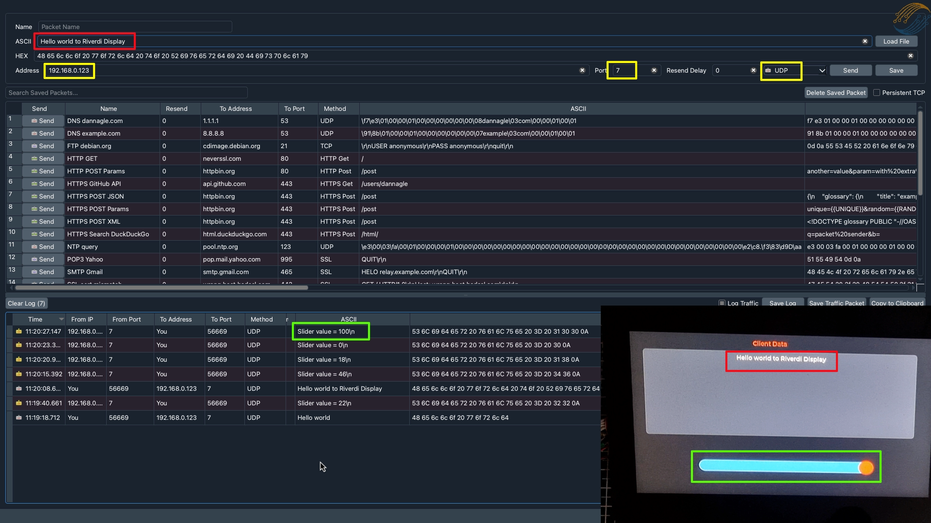
- The Yellow boxes shows the server Address and Port where the client is connected to.
- The Red boxes shows the data sent by the client and this data is displayed on the LCD.
- The Green boxes shows the slider on the display and the corresponding data sent to the client.


hi
i want to start modbus tcp/ip with stm32f407vgt6
that i can control gpio output via modbus tcp/ip but idon,t know what should i do
pleaaaaaaaaaaaaaaaaase help me and guide me
Hi, thanks for this guide!
I have used it for the 10 inch riverdi display and it almost works. It receives data correctly but when it send data it goes into hardfault after the data is sent.
Do you have any recommendations on what to change?
If you can debug, try to find out the execution sequence to know why it is happening.
Found the root of the problem being I used MQTT, and the hardfault came from mqtt.c:815. Removed the line and everything worked fine 🙂
815: r->cb(r->arg, ERR_OK);
r->arg was a null pointer for some reason. Weird there’s no check