Published: June 14, 2021
Last Updated: March 23, 2026
Last Updated: March 23, 2026
How to use Timer Input Capture Mode in STM32
Measuring signal frequency and pulse width is a common task in many embedded projects. STM32 microcontrollers make this easy with the Input Capture feature of their timers. Using input capture, you can precisely measure the time between signal edges, which helps in applications like frequency counters, duty cycle measurements, pulse sensors, or decoding communication signals.
In this tutorial, we’ll learn how to configure STM32 Input Capture using CubeMX and HAL. We’ll set up the timer, enable interrupts, and write the HAL_TIM_IC_CaptureCallback() function to calculate both frequency and pulse width accurately. This step-by-step guide is beginner-friendly and works with most STM32 boards.
Recommended Resources:
This tutorial uses the Timer to generate the PWM output, which is then measured using the input capture. The PWM output tutorial is already covered and you should take a look at it first.
This tutorial marks the 4th installment in our ongoing STM32 Timer Series. In this session, we will focus on one of the most practical and powerful features of the timer peripheral — the Input Capture mode.
Introduction to STM32 Input Capture
Measuring the frequency or pulse width of an external signal is a very common requirement in embedded systems. Whether you’re working with sensors, PWM signals, communication protocols, or frequency counters, you need a reliable and accurate way to measure the time between signal edges.
STM32 microcontrollers make this task simple through a built-in Input Capture feature in their timers. Instead of relying on software loops or manual polling, the hardware captures timer values at the exact moment an input event occurs. This allows you to measure high-speed signals with excellent precision, without loading the CPU.
What is Input Capture in STM32?
Input Capture is a timer feature that lets the microcontroller record the value of a timer counter when an external signal edge (rising, falling, or both) is detected on a specific input pin.
Here’s how it works step by step:
- You configure a timer to run at a known clock frequency.
- You select one of the timer’s input capture channels and map it to a GPIO pin.
- When a signal transition occurs (for example, a rising edge), the hardware automatically stores the current timer value into a special capture register.
- An interrupt can be triggered, allowing your code to read the captured value immediately.
By recording the timer value at two consecutive edges, you can calculate the time difference between them. This time difference forms the basis for frequency and pulse width calculations.
For example:
- Capturing two rising edges gives the period of the signal, which can be converted to frequency.
- Capturing rising and falling edges lets you measure the high time of the pulse, which gives the pulse width or duty cycle.
The image below shows how STM32 Timer Input Capture uses three captured timer values to measure both signal frequency and pulse width. The timer runs continuously at a known clock rate, and each signal edge automatically stores the current timer count into a capture register. By capturing two consecutive rising edges, the signal period is obtained, which is then used to calculate the frequency. Capturing the falling edge between those rising edges allows measurement of the signal high time, which is used to determine pulse width and duty cycle.
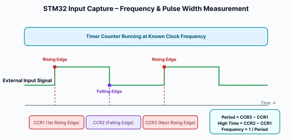
Because this process is handled by the timer hardware, it’s extremely precise and works even at high signal speeds.
Why Use Input Capture for Frequency and Pulse Measurement?
While you could try to measure signal timing using software loops or delay functions, those methods are prone to errors, jitter, and CPU delays — especially at higher frequencies. Input Capture eliminates these issues by using hardware-level timestamping.
Here are some key advantages of using Input Capture on STM32:
- High Accuracy: The timer captures events at the exact clock cycle, giving very precise measurements.
- Handles High Frequencies: Since the CPU isn’t constantly polling the pin, input capture works even with fast input signals.
- Automatic Measurement: Once configured, the timer hardware captures edges and generates interrupts automatically.
- Low CPU Usage: The processor only handles calculations after capture events, leaving more time for other tasks.
- Flexible Edge Detection: You can measure on rising edges, falling edges, or both — allowing frequency, pulse width, and duty cycle measurements with a single setup.
Circuit Diagram and Connections
In this tutorial, we’ll generate a PWM signal using TIM1 and feed it into TIM2 configured in Input Capture mode. This allows us to measure the frequency and pulse width of a known signal directly on the same STM32 board, without using any external signal generators.
This method is ideal for testing because both the signal generation and measurement happen inside the microcontroller. It reduces the chances of noise, wiring errors, or instability, giving you clean and accurate results.
Connecting TIM1 PWM Output to TIM2 Input Capture Pin
To measure a signal using Input Capture, we need a signal source. In this setup:
- TIM1 is configured in PWM output mode to generate a stable square wave signal at a known frequency (for example, 10 kHz).
- TIM2 is configured in Input Capture mode to measure this same signal.
- The PWM output pin of TIM1 is physically connected to the Input Capture pin of TIM2.
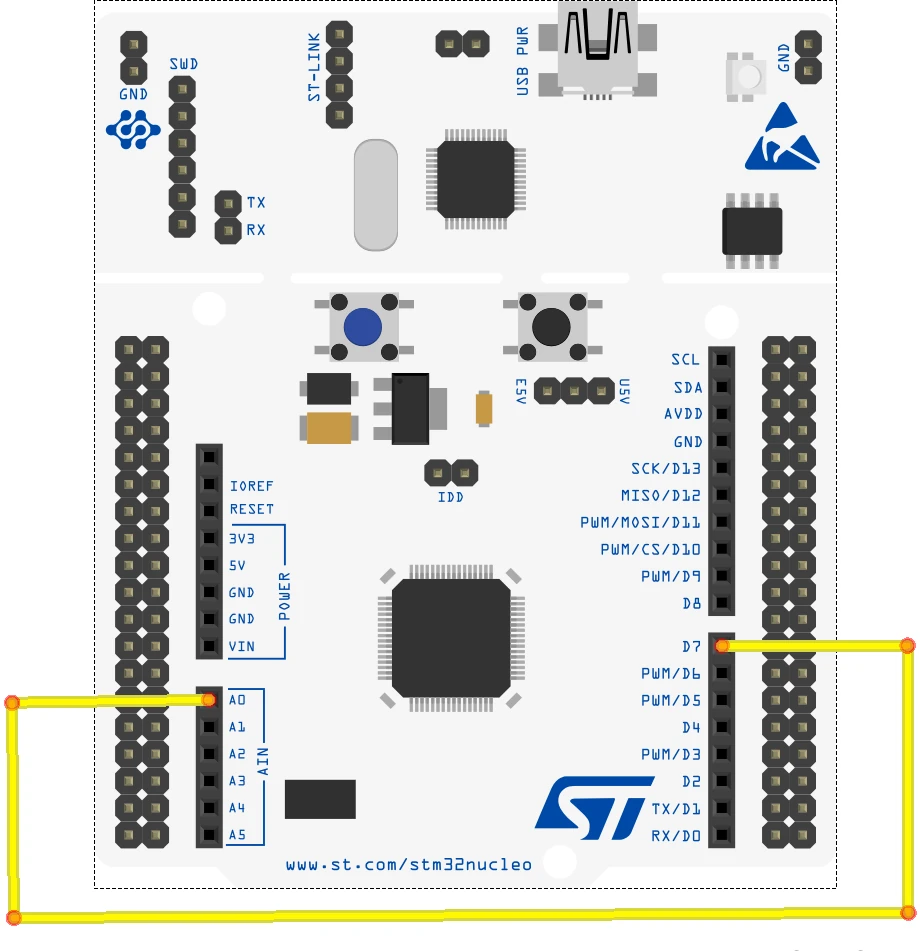
Here’s the basic connection:
| TIM1 (PWM Output) | TIM2 (Input Capture) | Connection Description |
|---|---|---|
| PA8 (TIM1_CH1) | PA0 (TIM2_CH1) | Connect this pin directly with a jumper wire |
PA8 is used because it corresponds to TIM1 Channel 1, which is a common pin for PWM output.
PA0 is selected for TIM2 Channel 1, which is frequently used for input capture on many STM32 boards.
Note:
Using one timer to generate a known signal and another timer to capture it is a common and reliable way to test Input Capture configurations during development.
STM32CubeMX Configuration for Input Capture
Before we write the code, we need to properly configure the timers and pins using STM32CubeMX. In this step, we’ll set up TIM1 to generate a PWM signal and TIM2 to capture that signal through its input capture channel.
STM32 Clock Configuration
Below is the image showing the clock configuration for the project.
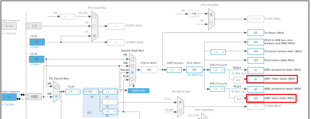
- Here we will use two timers, i.e Timer 1 for the PWM output and Timer 2 for the Input Capture
- Timer 1 is connected to the APB2, which is running at 180 MHz.
- Timer 2 is connected to the APB1, which is running at 90 MHz.
Timer Input Capture Configuration
Below is the image showing the configuration of the TIMER 2 for Input Capture Mode.
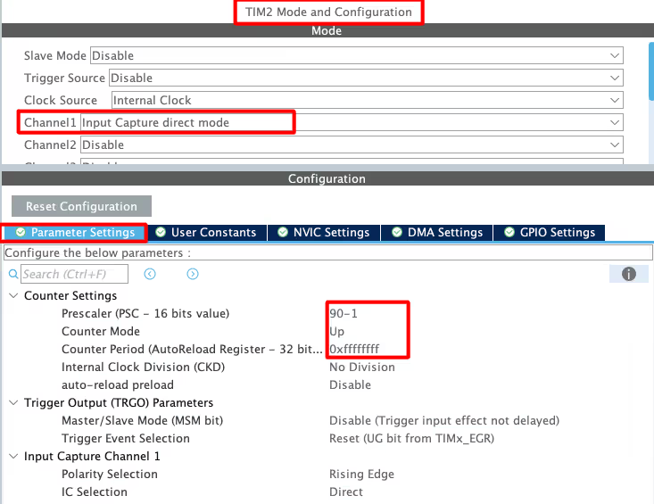
- Enable the Input capture Direct Mode on channel 1.
- The Prescaler is set to 90, which will divide the APB2 clock by 90, making the Timer 2 clock = 1 MHz.
- I am leaving the ARR to 0xffffffff (Max for 32 bit Timer).
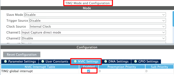
Also Enable the Interrupt for the TIM2. This allow the input Capture to trigger the interrupt, whenever the Rising / Falling Edge is detected.
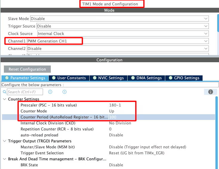
STM32 PWM Output Configuration
The TIMER1 is configured to output a PWM signal. If you want to know more about PWM output, check out the tutorial PWM (Pulse Width Modulation) in STM32.
Note:
Calculate the ARR and CCR values for the STM32F4 Timers using the STM32F4 PWM Tool:
https://controllerstech.com/tools/stm32f4-pwm-calculator/
How to Measure Frequency using Input Capture
In order to measure the Frequency of the input signal, we need to measure the time between the 2 rising edges, or between 2 falling edges.
- When the first Rising edge occurs, the counter value is recorded.
- Another counter value is recorded after the second rising edge occurs.
- Now the difference between these 2 counter values is calculated.
- This Difference in the counter values will give us the frequency.
STM32 HAL Code for Input Capture Frequency Measurement
This entire process is shown below.
#define TIMCLOCK   90000000
#define PRESCALAR  90

uint32_t IC_Val1 = 0;
uint32_t IC_Val2 = 0;
uint32_t Difference = 0;
int Is_First_Captured = 0;

/* Measure Frequency */
float frequency = 0;

void HAL_TIM_IC_CaptureCallback(TIM_HandleTypeDef *htim)
{
	if (htim->Channel == HAL_TIM_ACTIVE_CHANNEL_1)
	{
		if (Is_First_Captured==0) // if the first rising edge is not captured
		{
			IC_Val1 = HAL_TIM_ReadCapturedValue(htim, TIM_CHANNEL_1); // read the first value
			Is_First_Captured = 1;  // set the first captured as true
		}

		else   // If the first rising edge is captured, now we will capture the second edge
		{
			IC_Val2 = HAL_TIM_ReadCapturedValue(htim, TIM_CHANNEL_1);  // read second value

			if (IC_Val2 > IC_Val1)
			{
				Difference = IC_Val2-IC_Val1;
			}

			else if (IC_Val1 > IC_Val2)
			{
				Difference = (0xffffffff - IC_Val1) + IC_Val2;
			}

			float refClock = TIMCLOCK/(PRESCALAR);

			frequency = refClock/Difference;

			__HAL_TIM_SET_COUNTER(htim, 0);  // reset the counter
			Is_First_Captured = 0; // set it back to false
		}
	}
}- The above interrupt callback function is called whenever the Rising edge is detected.
- When called first time, Is_First_Captured was 0 so the hence the IC_Val1 will be recorded.
- When called after the second rising edge, the Is_First_Captured is 1 now so IC_Val2 will be recorded.
- We will calculate the Difference between the 2 IC values.
- Reference clock is calculated based on the setup we have done for our timer.
- Frequency is equal to the (Reference clock / Difference). This is because the counter value depends on the Timer clock.
In the main function, we have to start the TIMER in the Input capture interrupt mode.
I am also starting the Timer 1 in the PWM mode, so to provide the signal for the Timer2.
  TIM1->CCR1 = 50;
  HAL_TIM_PWM_Start(&htim1, TIM_CHANNEL_1);

HAL_TIM_IC_Start_IT(&htim2, TIM_CHANNEL_1);STM32 Input capture result
Below is the image showing the output of the above code.
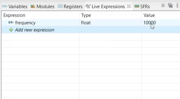
The Timer1 is configured to generate a PWM with frequency 10KHz. This PWM signal is fed to the input capture pin of Timer2. The image above shows the frequency measured by the Timer2 is equal to 10KHz.
How to Measure Pulse Width using Input Capture
To accurately measure the pulse width of an input signal, the timer interrupt must be configured to trigger on both the rising and falling edges of the signal. The rising edge marks the start of the pulse, while the falling edge indicates the end of the pulse. By capturing the timer value at both of these edges, we can calculate the exact high time of the signal. This high time represents the pulse width, which is especially useful when measuring PWM signals or duty cycles.
STM32 CubeMX Configuration
We need to modify the Input capture Configuration in CubeMX as shown below.
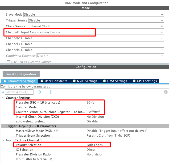
As you can see in the image above, I have switched the input capture Polarity to both the edges. This will make the interrupt to trigger for both the edges of the incoming signal.
Also Enable the Interrupt for the TIM2. This allow the input Capture to trigger the interrupt, whenever the Rising / Falling Edge is detected.
STM32 HAL Code to measure Pulse Width
- When the first rising edge occurs, The counter value is stored in the ICVal1.
- The next interrupt will occur at the falling edge, and the counter value is stored in the ICVal2.
- The Pulse width can be calculated using this counter value.
The process for the same is shown below
/* Measure Width */
uint32_t usWidth = 0;

void HAL_TIM_IC_CaptureCallback(TIM_HandleTypeDef *htim)
{
	if (htim->Channel == HAL_TIM_ACTIVE_CHANNEL_1)  // if the interrupt source is channel1
	{
		if (Is_First_Captured==0) // if the first value is not captured
		{
			IC_Val1 = HAL_TIM_ReadCapturedValue(htim, TIM_CHANNEL_1); // read the first value
			Is_First_Captured = 1;  // set the first captured as true
		}

		else   // if the first is already captured
		{
			IC_Val2 = HAL_TIM_ReadCapturedValue(htim, TIM_CHANNEL_1);  // read second value

			if (IC_Val2 > IC_Val1)
			{
				Difference = IC_Val2-IC_Val1;
			}

			else if (IC_Val1 > IC_Val2)
			{
				Difference = (0xffffffff - IC_Val1) + IC_Val2;
			}

			float refClock = TIMCLOCK/(PRESCALAR);
			float mFactor = 1000000/refClock;

			usWidth = Difference*mFactor;

			__HAL_TIM_SET_COUNTER(htim, 0);  // reset the counter
			Is_First_Captured = 0; // set it back to false
		}
	}
}- The above callback function is called when either the Rising or Falling edge is detected.
- When called for the rising edge, Is_First_Captured was 0 so the hence the IC_Val1 will be recorded.
- When called for the falling edge, the Is_First_Captured is 1 now so IC_Val2 will be recorded.
- We will then calculate the Difference between the 2 values.
- This difference is the time for which the Pulse is high, and this time will depend on the timer configuration.
- To measure this time in microseconds, we have to use the reference clock.
- Reference clock is calculated based on the setup we have done for our timer.
- And finally, the usWidth will be calculated.
Common Issues and Troubleshooting
Even after setting up the project correctly, you might encounter issues such as inaccurate frequency readings, unstable pulse width measurements, or timer capture not working as expected. These problems usually occur due to configuration errors, timer limitations, or missing interrupt settings. Below are some of the most common issues and how to fix them.
Incorrect Frequency or Pulse Width Readings
One of the most frequent issues when working with STM32 Input Capture is getting incorrect or unstable frequency and pulse width values. Here are some possible reasons and solutions:
- Wrong Timer Clock or Prescaler Settings
If the timer clock or prescaler values are not set correctly in CubeMX, the calculated time difference between captured edges will be wrong. Double-check theTIMCLOCKandPRESCALARvalues in your code to ensure they match the actual CubeMX configuration. - Using the Wrong Capture Channel
Make sure the input capture pin is mapped to the correct channel (e.g., PA0 for TIM2_CH1). If the wrong channel is selected, the timer will not capture any edges. - Edge Selection Not Configured Properly
For frequency measurement, capturing only on rising edges is usually enough. But for pulse width, you must enable both edges. If this is not done, the measured pulse width will be inaccurate or always zero. - Unstable Signal Source
If you are measuring from an external source, make sure the signal is clean and has sharp edges. Noisy signals or slow transitions can cause irregular readings.
Timer Overflow and Edge Detection Problems
Timer overflow is another common issue, especially when measuring low-frequency signals. If the period of the input signal is longer than the timer’s maximum count, the counter will overflow before the second edge is captured. This leads to negative or incorrect difference values.
To solve this:
- Use a 32-bit Timer if available, such as TIM2 or TIM5 on STM32F4/F7/H7 series. A 32-bit counter significantly increases the measurable period range.
- Adjust the Prescaler to lower the timer frequency, which extends the maximum measurable time between edges.
- Handle Overflow in Code: If overflow is possible, add logic in the capture callback to detect and compensate for it (as shown in the code section of this tutorial).
Also, make sure the edge detection mode matches your measurement type:
- For frequency → use rising edge only.
- For pulse width → enable both rising and falling edges.
Any mismatch here will lead to irregular or missing capture events.
CubeMX Configuration Mistakes
Many input capture problems can be traced back to CubeMX configuration errors. Even a small mistake in pin mapping or clock setup can cause the entire measurement to fail. Common misconfigurations include:
- Incorrect Pin Selection: Ensure the GPIO pin you select actually supports the desired timer channel and function. Use the Pinout view in CubeMX to verify this.
- Forgetting to Enable TIM Interrupts: If interrupts are not enabled for the input capture timer, the callback function will never be triggered. Check both the NVIC settings and the timer’s interrupt configuration.
- Wrong Clock Source or APB Prescaler: If the timer clock source doesn’t match the code’s assumed frequency, all calculations will be off. Reconfirm the clock tree settings under Clock Configuration.
- Not Generating Code After Changes: If you modify CubeMX settings but don’t regenerate the code, your project might still use the old configuration.
Video Tutorial
STM32 Input Capture Tutorial Video
This video explains how to use STM32 Input Capture to measure signal frequency and pulse width accurately.
You’ll see how to configure the timer in CubeMX, enable the input capture channel, and handle interrupts using HAL_TIM_IC_CaptureCallback().
The step-by-step video walkthrough makes it easy to follow the setup and understand the complete process from configuration to reading captured values.
Conclusion
In this tutorial, we explored how to use the Input Capture feature in STM32 to measure the frequency and pulse width of a signal accurately. Starting from understanding the concept of input capture, we went through the circuit connections, STM32CubeMX configuration, and code implementation. We also discussed how to handle both rising and falling edges for precise pulse width measurement and covered some common troubleshooting tips to avoid configuration errors.
By using input capture, you can offload timing measurements to the hardware timers, achieving high accuracy and real-time performance without relying on software delays. This technique is extremely useful in applications like PWM signal analysis, sensor data capture, frequency counters, and communication protocols.
More STM32 Timer Tutorials
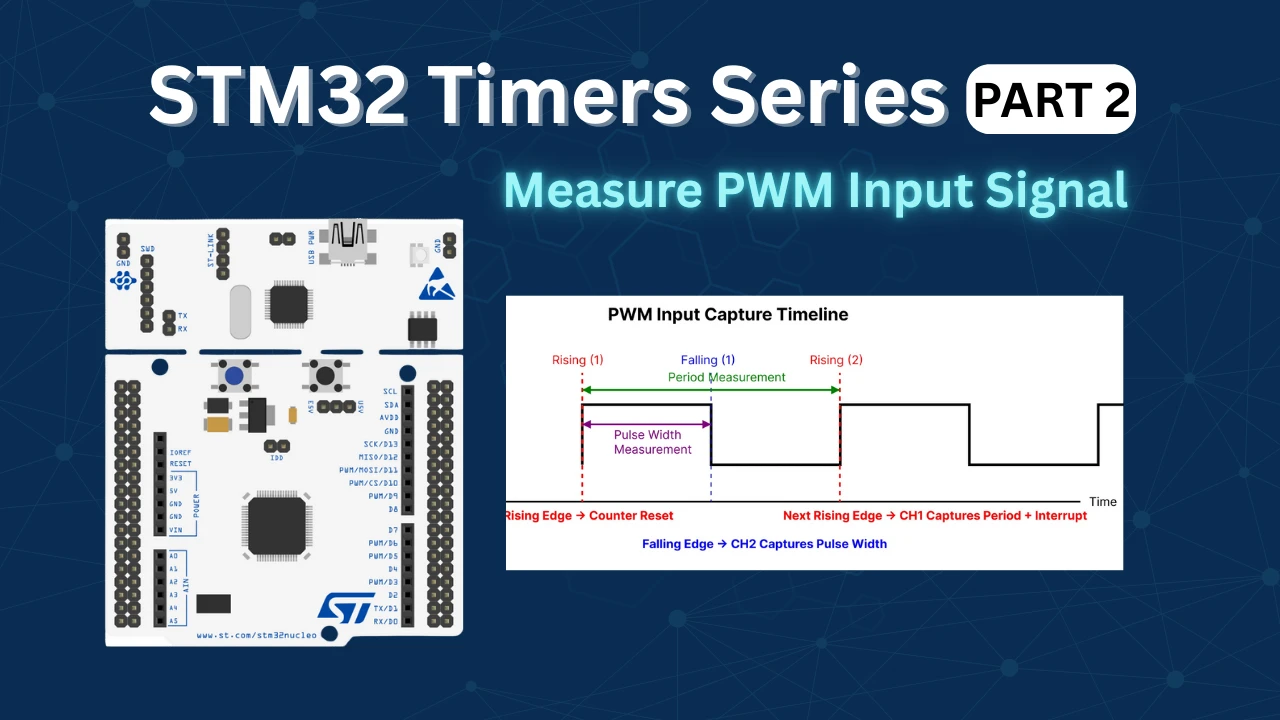
STM32 Timers (Part 2): How to Measure PWM Input Signal
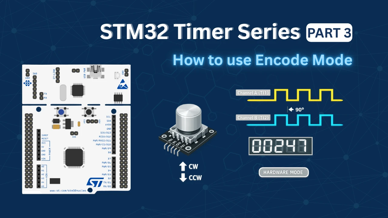
STM32 Timers (Part 3): How to use the Timer Encoder Mode
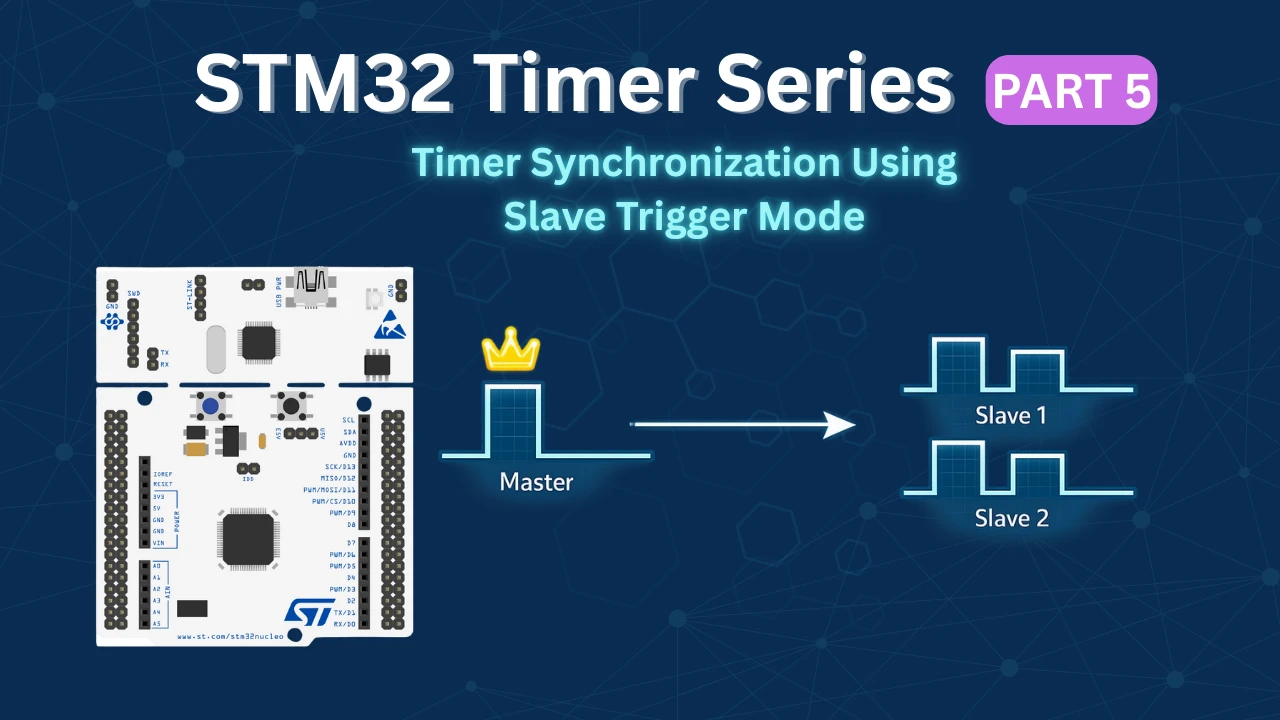
STM32 Timers (Part 5): STM32 Timer Synchronization Using Slave Trigger Mode
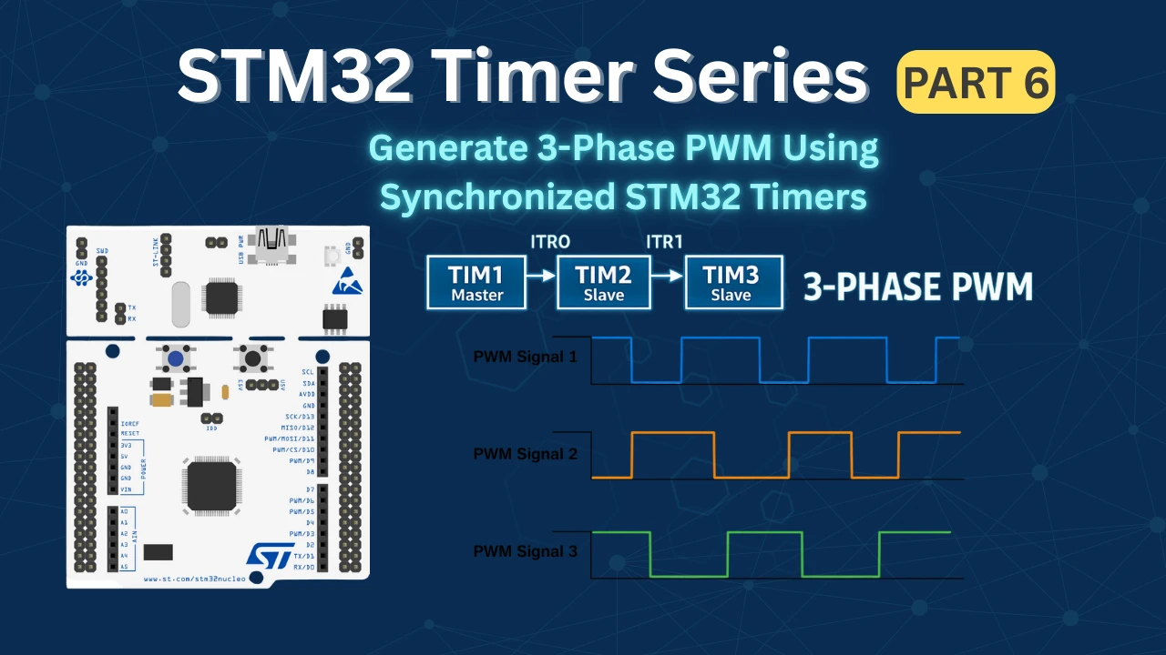
STM32 Timers (Part 6): Timer Synchronization for 3-Phase PWM Generation
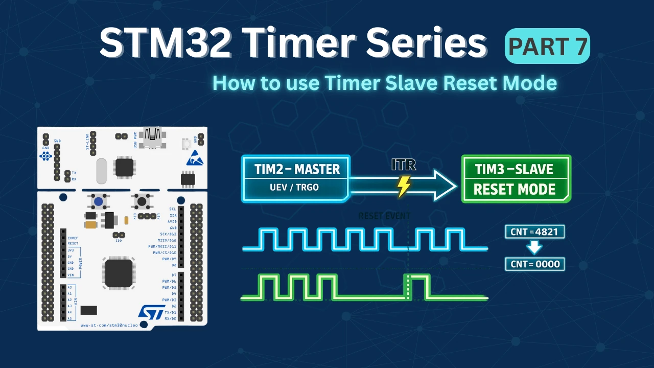
STM32 Timers (Part 7): Timer synchronization using Slave Reset mode
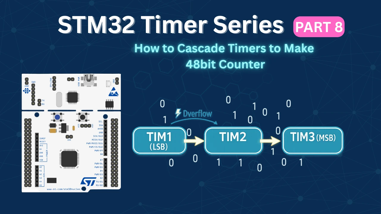
STM32 Timers (Part 8): How to Create a 48-Bit Counter by Cascading Timers

Hii Good afternoon,
I am using STM32F401re nucleo board, for measure the input capture frequency
but in that i am seeing frequency rising edge is not detect by
“IC_Val1 = HAL_TIM_ReadCapturedValue(htim1, TIM_CHANNEL_1);”
this function so value remain 0 as per this code.
please suggest what i should do?
Or can you suggest any other function to read the rising edge from register in Input Capture
my function is
void CaptureCallback(TIM_HandleTypeDef *htim1)
{
if (htim1->Channel == HAL_TIM_ACTIVE_CHANNEL_CLEARED)
{
if (Is_First_Captured==0) // if the first rising edge is not captured
{
IC_Val1 = HAL_TIM_ReadCapturedValue(htim1, TIM_CHANNEL_1); // read the first value
Is_First_Captured = 1; // set the first captured as true
}
else // If the first rising edge is captured, now we will capture the second edge
{
IC_Val2 = HAL_TIM_ReadCapturedValue(htim1, TIM_CHANNEL_1); // read second value
if (IC_Val2 > IC_Val1)
{
Difference = IC_Val2-IC_Val1;
}
else if (IC_Val1 > IC_Val2)
{
Difference = (0xffffffff – IC_Val1) + IC_Val2;
}
else if (IC_Val1 == IC_Val2)
{
Difference = IC_Val2;
}
float refClock = TIMCLOCK/(PRESCALAR);
frequency = refClock/Difference;
__HAL_TIM_SET_COUNTER(htim1, 0); // reset the counter to start
Is_First_Captured = 0; // set it back to false
}
}
}
uint32_t HAL_TIM_ReadCapturedValue(TIM_HandleTypeDef *htim, uint32_t Channel)
{
uint32_t tmpreg = 0U;
switch (Channel)
{
case TIM_CHANNEL_1:
{
/* Check the parameters */
assert_param(IS_TIM_CC1_INSTANCE(htim->Instance));
/* Return the capture 1 value */
tmpreg = htim->Instance->CCR1;
break;
}
case TIM_CHANNEL_2:
{
/* Check the parameters */
assert_param(IS_TIM_CC2_INSTANCE(htim->Instance));
/* Return the capture 2 value */
tmpreg = htim->Instance->CCR2;
break;
}
case TIM_CHANNEL_3:
{
/* Check the parameters */
assert_param(IS_TIM_CC3_INSTANCE(htim->Instance));
/* Return the capture 3 value */
tmpreg = htim->Instance->CCR3;
break;
}
case TIM_CHANNEL_4:
{
/* Check the parameters */
assert_param(IS_TIM_CC4_INSTANCE(htim->Instance));
/* Return the capture 4 value */
tmpreg = htim->Instance->CCR4;
break;
}
default:
break;
}
return tmpreg;
}
Here are both functions for your reference, Please suggest what changes are need.
Thank you.
Hi
When you measure the width- because trigger is both edges, how do you know that the first interrupt is the rising? if duty cycle is NOT 50% as here , if the interrupt is will be due the falling you will measure the low width od the pulse.You have to check the cause to the interrrupt is falling or rising and calculate the 2 width of the signal – the high part and the low part.Is it? Can I know what was the edge while enter the interrupt?
incrivel artigo sobre stm32
can i have your tutorials in just register level based , using HAL and all makes it very convoluted and i guess its not the best practise to do so .
Thank you so much.
I have learned from you.
It is very clear and understandable even for the beginners.
i initially started with this technique, but found that with this model that the interrupts are proportional to the frequency being measured, and you quickly saturate the MPU with interrupts (as you noticed) leaving you with nothing but an interrupt generation machine as the freq of the signal to be measured goes up, with no cycles left for anything else. In my case I am trying to measure the freq of an external input. what i did was use one timer to provide/manage the “gate” for another timer, and CLOCK the second timer with the external freq to be measured. now the interrupt rate is independent of my “unknown” frequency, and i am readily able to measure frequencies over 30mhz, with a gate frequency of 250ms (created by the first timer by linking the second to the first timer). connect the input being measured to the external clock source of the second timer (note- not all STM32 timers allow external clock source). In my case, T3 gates T2, T3 is setup with MasterslaveOutTrig = TRG0_OC1REF and MasterSlaveMode enabled, T2 is setup with CLKSRC=ETRMODE2 and SLAVEMODE=SLAVEMODE_GATED ITR2. in the T3 PeriodElapsed callback, read T2’s counter directly as the frequency
I think I met your issue that jam the interrupts… and agree that alternative is best to measure some high speed tachometer PWM inputs.
unfortunately, I cant fully get your solution in your message.
Hi man, please how do I measure the speed of a bldc motor by capturing the hall sensor signals (H1,H2,H3) on an STM32. Do you mind refering me to a video or link if you have one?
Hi man, please how do I measure the speed of a bldc motor by capturing the hall sensor signals (H1,H2,H3)
Coming from article where the main issue was code getting stuck in the frequency counter loop.
I just wanted to share how I configured my project to get this working in STM32CubeIDE v1.4.0 and STM32F103C8T6 (aka blue pill) board.
I set my clock configuration as follows:
HCLK (Mhz) set to “72”
APB1 Prescaler set to “/4”
resulting in APB1 Timer clocks of 36 Mhz
By the same token I set my parameters as:
Prescaler (PSC – 16 bits value) = 0
Counter Period (AutoReload Register – 16 bits value) = 65535
Code wise on the frequncy calculation changed:
Frequency = 2 * HAL_RCC_GetPCLK1Freq() / Difference;
According to the calculation lowest measureable frequnechy is 549 Hz.
36 * 1000 * 1000 / 65536 = 549.316 Hz
What options do I have if I want to measure signals at 200 Hz? Adjust APB1 Prescaler from “/4” to “/16” seem to do the trick but is the right way to do it?
9 * 1000 * 1000 / 65536 = 137.329 Hz
yes you did it right. As per with this code, you need to reduce the sysclock inorder to measure the lower frequencies
Helo
I tried this code and working fine . But when frequency increase , after about 36kHz the main loop stops to work . When decrease the frequency , main loop begins to work again . But frequency measurement still fine even main loop stop. Do you have any advice ?
what you mean main loop stops ?
Inan want to say …. what ever he writes in while loop thats not working when frequency increases …. it is because when frequency increase callback function interrupts increases with it and cpu do not get extra time to perform while loop code out of interrupt … when decrease frequency cpu get out of interrupt for some time and get some extra time to run while loop code also …. if there is any way to fix it im also interested to know
i don’t think it will work. One way you could try is instead of putting the entire code in the callback, just use some flag, and put the code in the while loop.
maybe that could work
I’m facing a similar problem, I can read up to 115Khz, but anything high causes my stm32 to stop work properly, I’m also using serial com and the board stop to receive RX but still send TX.
Well that may be because the uart baud rate could be 115200.
i saw that if i use internal crystal and low working frequency(16 Mhz) at the cubemx , main loop stop to work at high frequency measures like 36 khz . I used external crystal and set max speed(168 Mhz) . now it is working perfect. thanks
thats great 😀😀 … always remember to put top gear 🚀🚀of ur hardware before exicute anything 😁😁😁
aswdf
Thanks for this example, works fine.
Thanks, this tutorial was super useful to get the capture inputs working. Showing both the code and cube mx configuration did the trick.
Hello! Thank you for your tutorial! Could I ask what to do if the rising edge will come in two channels at the same time?