Home ▸ STM32 Tutorials ▸ ADC Series ▸
Updated On: April 16, 2026
STM32 ADC Multiple Channels with Circular DMA: CubeMX Setup & HAL Code
In this part of the STM32 ADC tutorial series, we will learn how to read data from multiple channels using DMA Circular Mode. Unlike Normal Mode, Circular DMA continuously transfers the converted values into memory without stopping, making it ideal for applications that require real-time and continuous data acquisition. This approach reduces CPU overhead since the DMA automatically restarts after completing a sequence. We will configure the ADC in CubeMX, generate the code, and test the results on STM32 boards.
This tutorial is a continuation of the previous one, so the configuration remains the same. This is the continuation of PART1 and PART2, so you must read them first.
This is the 4th tutorial in the STM32 ADC series. You can go through the other parts of this series, here are the links:
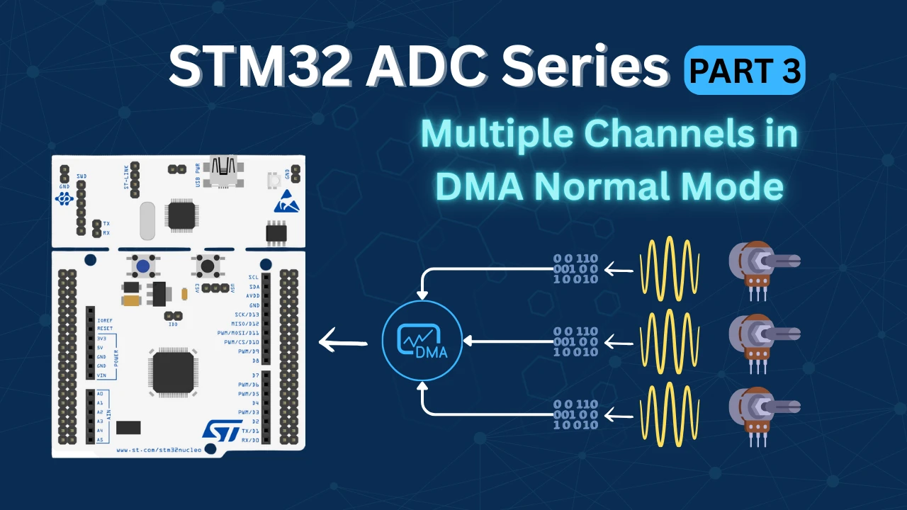
- STM32 ADC Multiple channels with DMA in Normal Mode
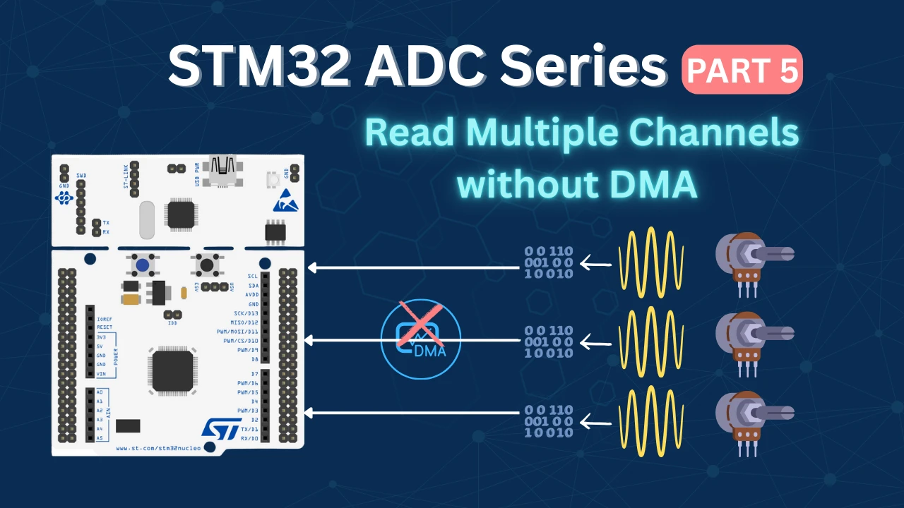
- Multiple Channels Without DMA | Full Control
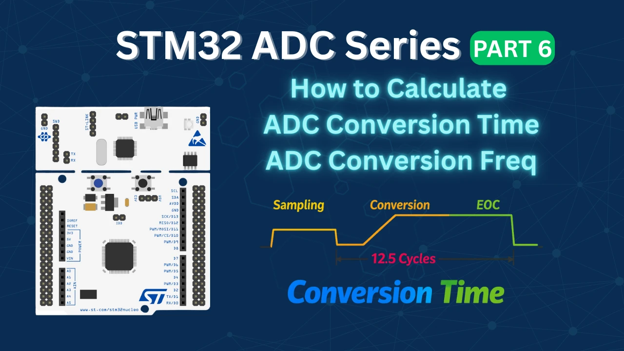
- STM32 ADC Conversion Time & Frequency Explained
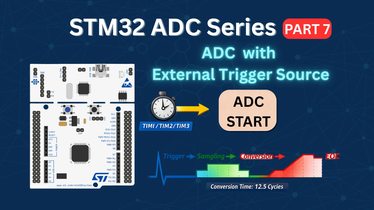
- ADC External Trigger Source Selection
- ADC Injected Conversion Mode
Table Of Contents
- How STM32 ADC Circular DMA Works: Continuous Transfer Explained
- STM32 ADC Circular vs Normal vs Interrupt: Mode Comparison
- STM32 ADC Multi-Channel Wiring: Pins & Potentiometer Setup
- STM32 ADC Circular DMA CubeMX Setup: F103, F446 & H750
- STM32 ADC Circular DMA HAL Code: Start & Conversion Callback
- STM32 ADC Circular DMA Output: Real-Time Debugger Results
- STM32 ADC Multi-Channel Circular DMA — Video Tutorial
- Download STM32 ADC Multi-Channel Circular DMA Project Files
- STM32 ADC Circular DMA: Frequently Asked Questions
How STM32 ADC Circular DMA Works: Continuous Transfer Explained
In STM32, the ADC (Analog-to-Digital Converter) can sample multiple channels (e.g., potentiometers, sensors, or input signals). To move the conversion results from the ADC peripheral to memory efficiently, we use DMA (Direct Memory Access).
In Multi-Channel DMA Circular Mode, the ADC samples several channels in sequence, and the DMA transfers each conversion result into memory (typically an array).
Once the DMA finishes storing the configured sequence, instead of stopping, it automatically loops back and starts writing new data at the beginning of the buffer. This creates a continuous stream of updated ADC values without any CPU intervention.
At any point, the CPU can access the buffer to process the most recent values.
Why use Circular Mode vs Normal / Interrupt?
- Circular Mode continuously refreshes the buffer with the latest ADC data, making it perfect for real-time applications where uninterrupted sampling is required.
- Normal Mode stops after one complete sequence, requiring the CPU or software to restart it, which is more suited for periodic sampling.
- Interrupt Mode doesn’t use DMA. The CPU handles each conversion individually, which increases overhead and is less efficient for multiple channels.
Advantages of Circular Mode
- Provides continuous sampling without manual restarts.
- Offloads the CPU, since DMA handles all transfers automatically.
- Ensures that the buffer always contains the most up-to-date conversion results.
- Ideal for high-speed, real-time applications.
Limitations of Circular Mode
- Data Overwrite: Old values are replaced with new ones, so if the CPU doesn’t read in time, some data may be lost.
- Slightly more complex to handle compared to Normal Mode.
- May require synchronization logic to ensure the CPU reads consistent data.
Best Use Cases for Circular Mode
- Real-time sensor monitoring (e.g., temperature, pressure, or motion sensors).
- Motor control applications where continuous feedback is essential.
- Audio signal sampling or waveform analysis.
- Any application where uninterrupted, high-speed data acquisition is required.
STM32 ADC Circular vs Normal vs Interrupt: Mode Comparison
The table below summarises the Advantages, Limitations and use cases for various ADC modes.
| Mode | How it Works | Advantages | Limitations | Best Use Cases |
|---|---|---|---|---|
| DMA Normal | ADC samples multiple channels → DMA stores results in memory → stops automatically after one sequence. | – Simple and efficient for batch conversions- No buffer overwrite- Low CPU load | – DMA must be restarted for next sequence- Not continuous | Snapshot readings of multiple sensors, periodic measurements |
| DMA Circular | ADC samples continuously → DMA keeps overwriting buffer in a loop. | – Continuous, real-time data- Low CPU load- No manual restart needed | – Data can be overwritten if CPU doesn’t read fast enough- Harder to capture “exact” snapshot | Continuous sensor monitoring, audio processing, streaming data |
| Interrupt | ADC signals CPU after each conversion → CPU reads data manually. | – Easy to implement- Fine control over each conversion | – High CPU overhead- Not efficient for multiple channels- Slower response at high sampling rates | Simple applications, single-channel ADC, low-speed sensing |
STM32 ADC Multi-Channel Wiring: Pins & Potentiometer Setup
The image below shows the connection between STM32H750 and the multiple Potentiometers.
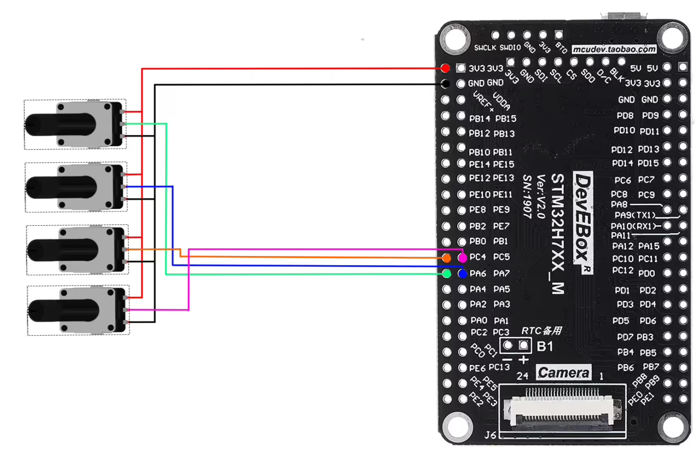
As shown in the image above, four potentiometers are connected to four pins of the MCU. All potentiometers share the same 3.3V supply and GND from the MCU. Only the wiper (signal pin) of each potentiometer is connected to a unique ADC-capable pin on the STM32.
The pin connection is described in the table below.
| Potentiometer | Pin 1 (VCC) | Pin 2 (Signal / Wiper) | Pin 3 (GND) | MCU Pin (ADC Channel) |
|---|---|---|---|---|
| Potentiometer 1 | 3.3V | Middle Pin → Pink Wire | GND | PC5 (ADC Channel 15) |
| Potentiometer 2 | 3.3V | Middle Pin → Orange Wire | GND | PC4 (ADC Channel 14) |
| Potentiometer 3 | 3.3V | Middle Pin → Blue Wire | GND | PA6 (ADC Channel 6) |
| Potentiometer 4 | 3.3V | Middle Pin → Green Wire | GND | PA6 (ADC Channel 6) |
STM32 ADC Circular DMA CubeMX Setup: F103, F446 & H750
We will connect 4 potentiometers to the 4 channels of the same ADC. As I mentioned we will setup the DMA in Circular mode, so it will continue to transfer the data from ADC channels.
We will see the available configuration for all three MCUs, F103C8, F446RE and H750VB.
STM32F103C8 ADC DMA Configuration
The image below shows the configuration for STM32F103C8 ADC multiple channels using DMA Normal Mode.
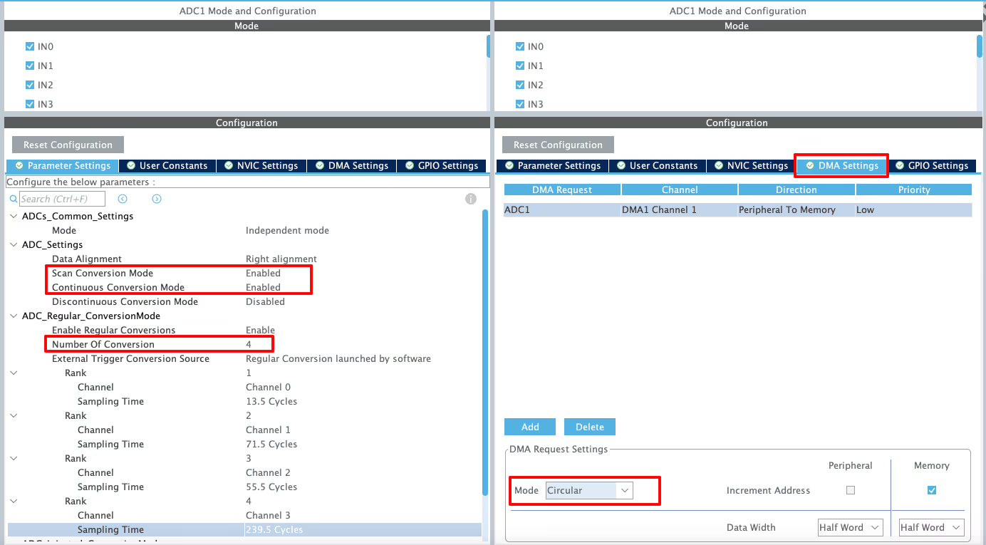
I have enabled 4 channels of the ADC1. This is where the 4 potentiometers will be connected to.
Since we are using 4 different Channels of ADC1, set the Number of Conversions (under ADC_Regular_ConversionMode) to 4. This will automatically enable the Scan Conversion Mode, which is necessary in case of Multiple Channels.
You can configure the Rank and Sampling Time for each channel. The Rank determines the sequence in which the channels will be converted.
The Continuous Conversion Mode should be Enabled. Doing so will make sure the ADC start another conversion for all the channels automatically. This way the ADC will keep converting the data continuously.
In the DMA section, add the DMA request for the ADC1. Also make sure that the DMA is configured in the Circular Mode. In this mode the DMA will transfer the data continuously.
on by default and we don’t have the option to configure it. Therefore the data width for the DMA must be set to Half-Word (16 bits).
STM32F446 ADC DMA Configuration
The image below shows the configuration for STM32F446RE ADC multiple channels using DMA Normal Mode.
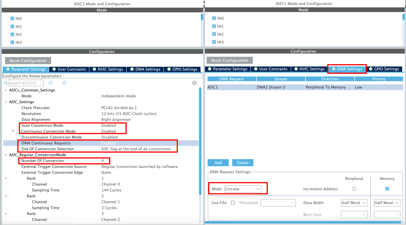
I have enabled 4 channels of the ADC1. This is where the 4 potentiometers will be connected to.
Since we are using 4 different Channels of ADC1, set the Number of Conversions (under ADC_Regular_ConversionMode) to 4. This will automatically enable the Scan Conversion Mode, which is necessary in case of Multiple Channels.
You can configure the Rank and Sampling Time for each channel. The Rank determines the sequence in which the channels will be converted.
The Continuous Conversion Mode should be Enabled. Doing so will make sure the ADC start another conversion for all the channels automatically. This way the ADC will keep converting the data continuously.
The DMA Continuous Request must also be Enabled. This is to make sure that the DMA requests the data continuously from the ADC. This mode should be kept Enabled while using the DMA in Circular mode.
The End of Conversion Selection should be set at the end of all the conversions. Doing this will make sure that the Conversion complete interrupt in only triggered when all the 4 channels (one complete sequence) have been converted.
In the DMA section, add the DMA request for the ADC1. Also make sure that the DMA is configured in the Circular Mode. In this mode the DMA will transfer the data continuously. Set the data width as per the ADC Resolution. I have configured the ADC with 12bits resolution, therefore the data width is set to half word (16bits).
STM32H7 ADC DMA Configuration
The image below shows the configuration for STM32H750 ADC multiple channels using DMA Normal Mode.
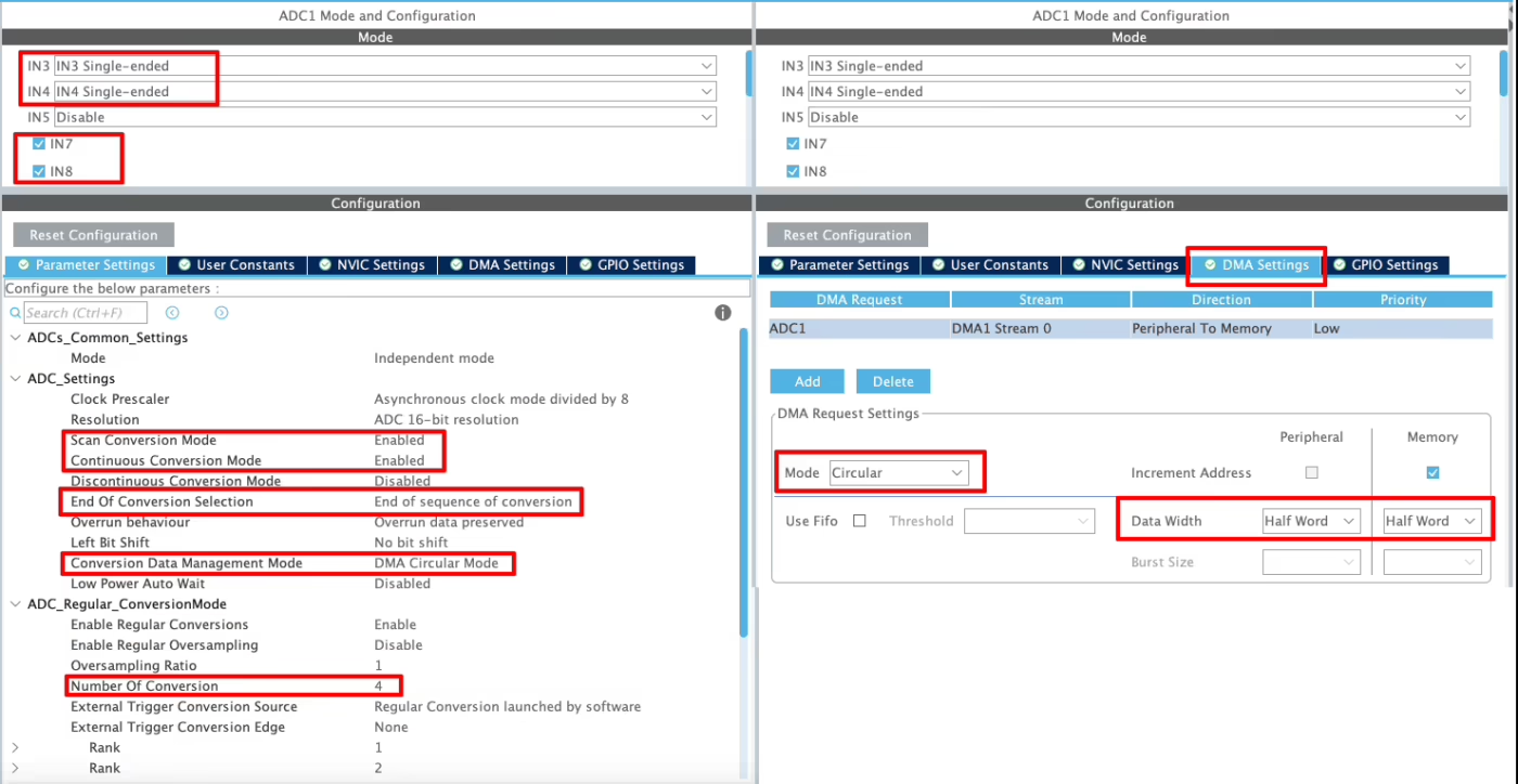
I have enabled 4 channels of the ADC1. This is where the 4 potentiometers will be connected to.
Since we are using 4 different Channels of ADC1, set the Number of Conversions (under ADC_Regular_ConversionMode) to 4. This will automatically enable the Scan Conversion Mode, which is necessary in case of Multiple Channels.
You can configure the Rank and Sampling Time for each channel. The Rank determines the sequence in which the channels will be converted.
The Continuous Conversion Mode should be Enabled. Doing so will make sure the ADC start another conversion for all the channels automatically. This way the ADC will keep converting the data continuously.
The Conversion Data Management Mode should be set to DMA Circular. This is to make sure that the DMA does requests the data continuously from the ADC. This mode should be used while using the DMA in Circular mode.
The End of Conversion Selection should be set at the end of sequence of conversion. Doing this will make sure that the Conversion complete interrupt in only triggered when all the 4 channels (one complete sequence) have been converted.
In the DMA section, add the DMA request for the ADC1. Also make sure that the DMA is configured in the Circular Mode. In this mode the DMA will transfer the data continuously. I have configured the ADC resolution of 16bits, therefore the data width is set to Half-Word (16bits).
Cortex-M7 Specific Configuration for ADC with DMA
In this section we will cover the configuration and code exclusively needed for the cortex M7 devices.
We know that as per ST’s recommendation, we should use the Instruction and Data cache to improve the system performance. But if the cache are enabled, the DMA will always have the cache coherency issue. This is why we will use the Memory Processing Unit (MPU) of the cortex M7 to deal with the cache coherency.
Below is the image showing the MPU configuration in the cortex M7 Devices.
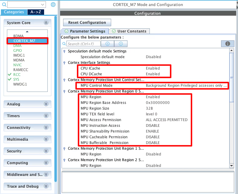
As you can see in the image above, I have enabled both Instruction and Data Cache (ICache & DCache).
We also need to enable the MPU in the MPU_PRIVILEGED_DEFAULT mode. Here I am choosing the Base Address region 0x30000000, this is the region for the RAM_D2 and we will relocate our buffer in this region.
- Here I have selected the 32 Bytes region, since it’s the least size available. The ADC Buffer is going to be 20 bytes in size.
- The rest of the configuration is to set the region as non-cacheable region. This would prevent the cache coherency issue between the CPU and the DMA.
In the main file, we need to relocate the ADC_VAL array to the RAM_D2 Region, 0x30000000. We can do this by using the section attribute as shown below. Here I am relocating the ADC_VAL array to the section “.adcarray“.
__attribute__((section(".adcarray"))) uint16_t ADC_VAL[4];Next, define the section (.adcarray) in the flash script file as shown below.
  .mysection (NOLOAD):
  {
    . = ABSOLUTE(0x30000000);
    *(.adcarray)
} >RAM_D2As you can see above, the section (.adcarray) is linked to the region RAM_D2 (0x30000000).
The rest of the code remains the same as we used in the DMA section.
STM32 ADC Circular DMA HAL Code: Start & Conversion Callback
The code will remain the same for all the STM32 MCUs. If there are any changes, I will specify in this section itself.
Definitions
Let’s define some variables, which we will use in the main function later.
uint16_t ADC_VAL[4];
//__attribute__((section(".adcarray"))) uint16_t ADC_VAL[4];  // cortex M7 only
int count = 0;ADC_VAL is an array of 4 elements of 16 bit in size. We will use this array to store the converted ADC Value. The ADC always defines ADC_VAL as a 16-bit variable, even when you use 10-bit, 12-bit, or 14-bit resolution.
The count variable will keep track if the rest of the while loop is working fine.
The main function
Below is the main function.
int main ()
{
  ....
  ....
  HAL_ADC_Start_DMA(&hadc1, ADC_VAL, 4);
  while (1)
  {
    count++;
    HAL_Delay(500);
  }
}Inside the main function, we will start the ADC in the DMA mode. The parameter ADC_VAL is the array where we want to store the converted data, and 4 is the number of conversions we want the DMA to transfer.
After the DMA transfers the converted data from all channels, it triggers an interrupt that calls the Conversion Complete callback. The DMA will again restart the transfer request from the ADC, and this process will continue forever.
ADC Conversion Complete Callback
void HAL_ADC_ConvCpltCallback(ADC_HandleTypeDef *hadc)
{
  // Process the data
}Inside the callback we can process the received data or set another variable. This variable indicate that the DMA has finished the transfer and we can now process the data anywhere in the code.
In circular mode, the DMA will continue transferring the data for all the channels. Therefore we do not need to start the ADC in DMA mode again.
STM32 ADC Circular DMA Output: Real-Time Debugger Results
The video below shows the ADC values obtained by rotating the potentiometers, in the STM32CubeIDE debugger.
As you can see in the video, the element of the ADC_VAL buffer is changing with the rotation of the respective potentiometer. The data is not updating every 500ms.
The DMA transfers the data when the while loop calls it (every 500 ms), and it works fine even with the cache enabled. There is no issue of the cache coherency, otherwise the data in the ADC_VAL array would not update at all.
STM32 ADC Multi-Channel Circular DMA — Video Tutorial
Watch the complete walkthrough of this tutorial — configuring multiple ADC channels in DMA Circular Mode in CubeMX for STM32F103, F446, and H750, enabling continuous conversion and DMA circular request, writing the HAL code, handling the conversion complete callback, and verifying continuously updating multi-channel results in the STM32CubeIDE debugger.
Download STM32 ADC Multi-Channel Circular DMA Project Files
CubeMX configuration and HAL source code for reading multiple ADC channels in DMA Circular Mode — tested on STM32F103, F446, and H750. Free to download — support the work if it helped you.
STM32 ADC Circular DMA: Frequently Asked Questions
Conclusion
In this tutorial, we explored how to configure STM32 ADC for Multi-Channel DMA Circular Mode. Unlike Normal Mode, Circular DMA allows the ADC to continuously refresh a memory buffer with new conversion results, making it ideal for applications that require real-time and uninterrupted data acquisition. This approach not only reduces CPU load but also ensures that the latest values from all channels are always available for processing.
While Circular DMA is powerful for continuous sampling, it may not always be necessary. In some cases, you may prefer to avoid DMA altogether and directly handle ADC conversions through software.
In the next part of this series, we’ll learn how to read multiple ADC channels without using DMA, giving you a better understanding of when to use DMA and when a simpler approach is sufficient.
Browse More STM32 ADC Tutorials
STM32 ADC Single Channel: Interrupt & DMA Mode with HAL Code
STM32 ADC Multiple Channels DMA Normal Mode – CubeMX & HAL Code
STM32 ADC Multiple Channels Without DMA: CubeMX Setup & HAL Code
STM32 ADC Conversion Time: Formula, Calculation & Frequency Explained
STM32 ADC External Trigger with Timer: CubeMX & HAL Guide
STM32 ADC Injected Conversion Mode: Triggered & Auto Injection
STM32 ADC Hardware Oversampling: Improve Resolution & Reduce Noise


Hello, I’m trying to use the STM32H753ZI nucleo board with two ADG732 mux.. one mux connected to ADC1_INP2 and one mux connected to ADC1_INP3 for a total of 64 input channels. I need to scan both ADC channels, step mux address, and repeat, filling a ring buffer[64]. I put my DMA buffer in RAM_D3 as this area is a non-cacheable area, so I didnt need to mess with MPU/cache. However, its not working as intended. I can either get all 64 buffer spots to continuously show channel0 of their respective mux (buffer[0,2,4,6,8…] showing mux1 channel0 and buffer[1,3,5,7,9….] showing mux2 channel0), or they cycle through all 32 channels of their respective mux (buffer[0,2,4,6,8…] cycling through mux1 channel0,2,4,6,8… and buffer[1,3,5,7,9…] cycling through mux2 channel1,3,5,7,9…). I have not been able to get it to fill the buffer correctly (each buffer spot remains with its intended channel i.e. buffer[0] = mux1 channel0, buffer[1] = mux2 channel0, buffer[2] = mux1 channel1, and so on. Can you please help?
Hi, I am using same setup and code you have suggested for 446RE but when there is any change in one channel then it is affecting others as well. I am using sampling time for all 480 cycles. Any suggestions?
Awesome