STM32 ADC single channel
This tutorial will cover the ADC in STM32. We will be using a single channel, where one potentiometer is connected.
We will use all the possible ways of reading the ADC values. And those are PollForConversion, Interrupt and the DMA.
Before we start conversions, Let’s see some of the concepts we are going to use in ADC
Single conversion mode
In Single conversion mode the ADC does one conversion and than stops. You can select single conversion in CubeMx by setting continuousconversionmode as DISABLED.
Continuous conversion mode
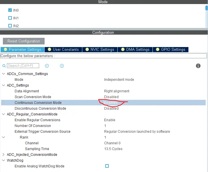
In continuous conversion mode ADC starts another conversion as soon as it finishes one. This method is more efficient if you want to convert continuously. You can select continuous conversion by setting continuousconversionmode as ENABLED.
Scan mode
This mode is used to scan a group of analog channels. This mode will be automatically selected if you are doing conversions for more than 1 channel. A single conversion is performed for each channel of the group. After each end of conversion the next channel of the group is converted automatically. If the continuousconversionmode is ENABLED, conversion does not stop at the last selected group channel but continues again from the first selected group channel. When using scan mode, DMA bit must be set and the direct memory access controller is used to transfer the converted data of regular group channels to SRAM after each update of the ADC_DR register.
Conversion time
According to the datasheet, the total conversion time is calculated as follows:
Tconv = Sampling time + 12.5 cycles
Example: With an ADCCLK = 14 MHz and a sampling time of 1.5 cycles: Tconv = 1.5 + 12.5 = 14 cycles = (14cycles/14MHz) = 1 µs
There is an entire article on the Conversion Time and Frequency calculation. You can read it https://controllerstech.com/adc-conversion-time-frequency-calculation-in-stm32/
Single channel using Poll for conversion
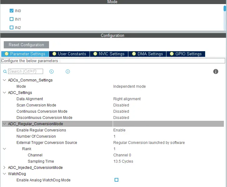
The CUBEMX Setup for the Poll For Conversion is shown Below. Here I am using only 1 channel and the continuous conversion is DISABLED.
Also the sampling time is 13.5 cycles which is around 1 us, as the ADC clock is 12MHz.
The code is as follows
HAL_ADC_Start(&hadc1); // start the adc

HAL_ADC_PollForConversion(&hadc1, 100); // poll for conversion

adc_val = HAL_ADC_GetValue(&hadc1); // get the adc value

HAL_ADC_Stop(&hadc1); // stop adc

HAL_Delay (500); // wait for 500ms- Pollforconversion is the easiest way to get the ADC values
- Here we will keep monitoring for the conversion in the blocking mode using
HAL_ADC_PollForConversion - Once the conversion is complete, we can read the value using
HAL_ADC_GetValue - And finally we will stop the ADC.
Single channel using INTERRUPT
Pollforconversion uses blocking mode to monitor for the conversion and is not an efficient way to use ADC. Using Interrupt is an alternate way to do so and let’s see How to use it
First we need to enable continuous conversion mode otherwise after single conversion, ADC will stop and we have to restart it.
Also make sure you enable the interrupt in the NVIC tab as shown below
First we have to start the ADC in the interrupt mode by using the function below
HAL_ADC_Start_IT (&hadc1);Now whenever the conversion is complete, a callback function is called and we are going to write the rest of the code inside it
void HAL_ADC_ConvCpltCallback(ADC_HandleTypeDef* hadc)
{
  adc_val = HAL_ADC_GetValue(&hadc1);
  /*If continuousconversion mode is DISABLED uncomment below*/
  //HAL_ADC_Start_IT (&hadc1);
}HAL_ADC_GetValuereads the value from ADC and stores it in the variable adc_val.- Also note that if the continuousconversion mode is disabled, ADC will stop here and we have to again start the conversion in interrupt mode.
Single channel using DMA
DMA is another way of getting data from ADC. Like interrupt mode, DMA method also works in a non-blocking mode.
That means we can use the rest of the program while the DMA would be keep fetching the value in the background and when needed, we can get the value.
DMA in Single Channel is Pointless, and it’s more useful in multi channel mode.
In DMA method, whenever the conversion is complete, the ADC values are saved in the buffer, and we can read them anytime we want. The setup for the DMA is shown below
- Circular DMA mode will ensure that the DMA will never stop
- Even after the conversion is complete, the counter will be reloaded and the DMA will start again automatically
- The Data width should selected as WORD / Half WORD, as the resolution is 12 bit
To start the ADC in DMA mode we have to use the function below
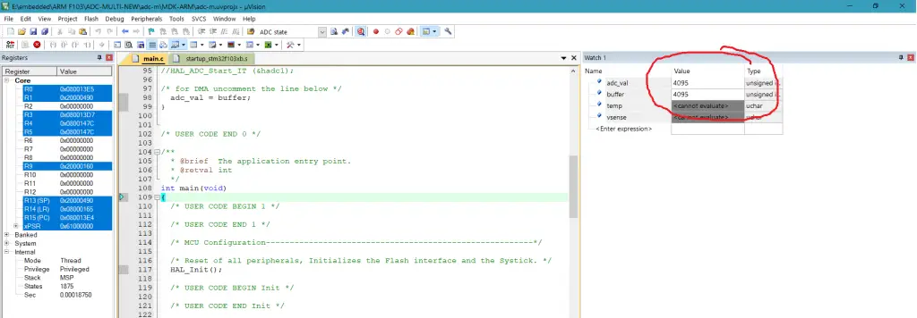
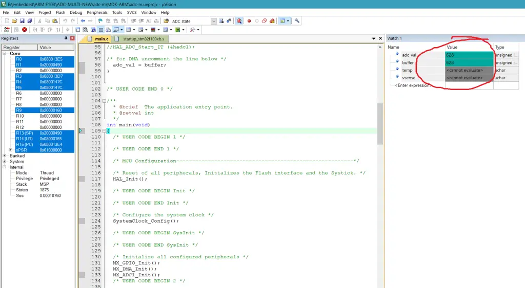
HAL_ADC_Start_DMA (&hadc1, &buffer, 1);This will start the ADC1 in DMA mode and the converted value will be stored in the buffer.
We can read the buffer at any point in the code and get the ADC value
void HAL_ADC_ConvCpltCallback(ADC_HandleTypeDef* hadc)
{
   adc_val = buffer;
}
Connection
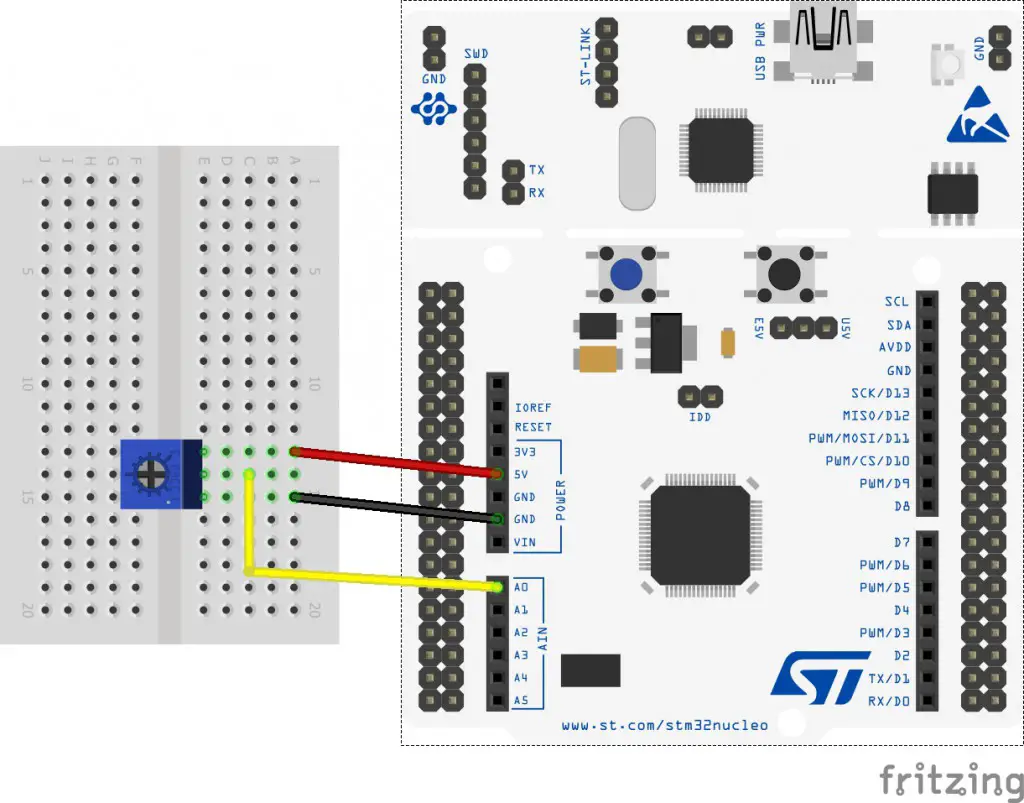
Here The potentiometer is connected to he PA0, which is ADC Channel 0.








14 Comments. Leave new
All recommendations are provided with hal.libraries.
A straight line by line example is always missing. Same it is with ST.micro.
At the end, when customers will be upset why this and that doesn’t work, and there are mistakes, the customers will move to a straght forward solution with different chip from somebody else. At this moment, ST can stick their chip to their ass.
I want to read only rising edge of waveform of 1khz after 50us after rising edge and want to skip other part which method should i use …
For interrupt, if I enable continuous conversion mode, my main while(1) can’t loop
That is because your interrupt is getting triggered at very high rate, so by the time the ISR exits, another interrupt is ready to be served.
You have to slow the interrupt rate. You can do the following
i work with stm32f446 , i do the conversion mode but all i get is a zero
You may also take a look at this tutorial:
https://www.researchgate.net/publication/354117675_STM32_ADC_TUTORIAL_with_application_to_real-time_control
i got the buffer value but adc_val not showing
if you have put it in the while loop, then it might not execute if the ADC clock is very high. Try reducing the ADC clock in that case
I am trying to produce a oscilloscope-like project. I am curious about that how much sample can i get from 6 channel adcs.
Give it a go and see…
i have been trying to parse GPS value and separately print latitude and longitude. but all i get is a zero.so please can you help me in it
Gps modules work with serial transmission and not with ADC.
You should work with uart.
What is the resolution for this example since stm32f103 has been used.
İf the reading between 0>>3.3 V what is the range for the adc_val ?
If you are using CubeMx than resolution is set to 12 bits. It doesn’t matter what is the range for the ADC values you are reading. This is where the Vsense comes in. Vsense is equal to ((3.3-0)/4096)*adc_value. This gives you a reading in terms of the voltage.