How to send data via the UART
This is the 4th tutorial in the AVR series. In the previous tutorial we saw how to use the output compare mode of the timer0. I also mentioned that we will use this mode for some of the peripherals.
So today in this tutorial, we will use the interrupt generated by the output compare mode to send the data as in a UART format. We will read the data in a serial monitor on the computer, and it will recognise it as a valid UART data.
Basically we will use the bit banging for the UART, instead of using the peripheral itself. The data will be received by the computer and it should be able to treat it as a valid UART data.
I would recommend you guys to go through the previous tutorial first, as I will skip the timer setup part in this one.
How it works ?
Every communication protocol has its own format with certain rules. UART is no different. The simplified UART format is shown in the picture below.
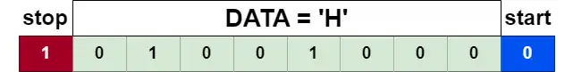
The picture above shows the basic UART format. The 8 bit data must be in between the START bit and the STOP bit.
The START bit represents a 0, where the Data pin Transits from HIGH to LOW state. The STOP bit represents a 1, where the data pin is HIGH irrespective of the previous state.
The data is sent as the LSB (Least Significant Bit) first. That means the START bit is sent first, followed by the 8 bit data which is followed by the STOP bit.
So the complete UART data actually consists of 10 bits. Each bit must transmit at a standard rate. We will use the most common 9600 bits per second.
This simply means that the MCU should set or reset the Data pin 9600 times in 1 second.
In order to achieve this, the interrupt should also generate at 9600 hertz. For each call of the ISR, we can set or reset the pin, based on what data we are sending.
The CODE
Timer setup
The Timer setup will remain same as what we did in the previous project.
void timer_init (void)
{
	TCCR0A = 1<<WGM01;  // enable CTC for TIM0
	OCR0A = 103;
	TIMSK = 1<<OCIE0A;  // enable interrupt for comapare match A
	sei();  // enable interrupt
}
The timer initialization is already covered in the previous tutorial. It is mostly same here except the compare value (OCR0A) and the fact that we are not setting the prescaler yet.
You already know that the interrupt generation rate can be controlled by 2 factors. The timer clock and the compare value. If we want to generate the interrupt at 9600 Hz, we keep the timer clock at 1MHz and use the compare value of 104.
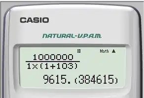
We get approximately the same rate that we want. The prescaler is set as 1 in the above calculation.
Setting the prescaler for the timer also enables the timer. So we will do that later, once we have the data to be sent.
Set up the DATA
Since we are not using the UART peripheral, we need to manually set the data in a format that it can be recognised as UART data. I have already explained how this data is going to be, so let’s set it up.
volatile uint16_t maindata = 0;

void uart_char (char c)
{
	maindata = c<<1;  // start bit 0
	maindata |= 1<<9;  // stop bit 1
	TCCR0B = 1<<CS00;  // start timer with no prescaler
}
The function uart_char is used to prepare the main data for a single character. The character is 8 bit in size and we know that we have to add a START and STOP bit to this.
- The character is shifted to the left by 1 place (c<<1). This adds a 0 (START bit) to the 1st position and the data is stored in the variable maindata.
- Then we shift a 1 to the left by 9 places (1<<9). This ads a 1 (STOP bit) to the 10th position and the maindata gets updated with the stop bit.
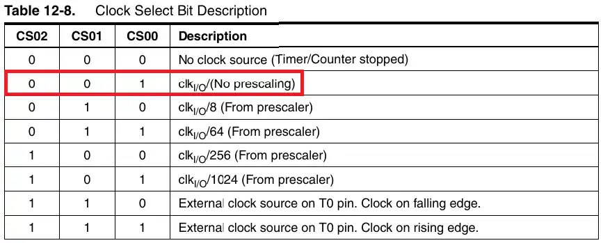
- Now the data is prepared, so we start the timer by setting the prescaler bits.
- We want the Timer clock to be same as the system clock, i.e. 1MHz, so we will start the timer with no prescaler. This is done by setting the bit CS00 in the TCCR0B Register.
Send the data
Once the timer starts, an interrupt will trigger after 1/9600 seconds. We will send our data in the Interrupt Handler.
// ISR will be called every 1/9600 seconds
ISR (TIM0_COMPA_vect)
{
	if (maindata & 0x01) PORTB |= 1<<PB0;  // set the pin PB0
	else PORTB &= ~(1<<PB0);  // Reset the pin PB0
	maindata = maindata >>1;

	if (maindata == 0)  // if all the data is sent
	{
		TCCR0B = 0;  // stop the timer
		TCNT0 = 0;  // reset the counter
	}
}
The maindata variable contains the 10 bits to be sent. The ISR is called 9600 times in a second and for each call, we will send 1 bit of data.
- We check the first bit of the maindata variable by performing the AND (&) operation with 0x01.
- If the bit is 1, set the data pin HIGH and if the bit is 0, set the data pin LOW.
- Shift the maindata to the right by 1 place. This will shift all the bits in the maindata to the right.
- The 2nd bit becomes the 1st bit, the 3rd bit becomes the 2nd bit and so on.
- The data pin will remain HIGH/LOW until the ISR is called again.
- The 1st bit of maindata is checked again and the state of the data pin is set according to this bit.
- This process repeats until all the 10 bits of the maindata variable are checked. Once it happens, the maindata will only contain 0s.
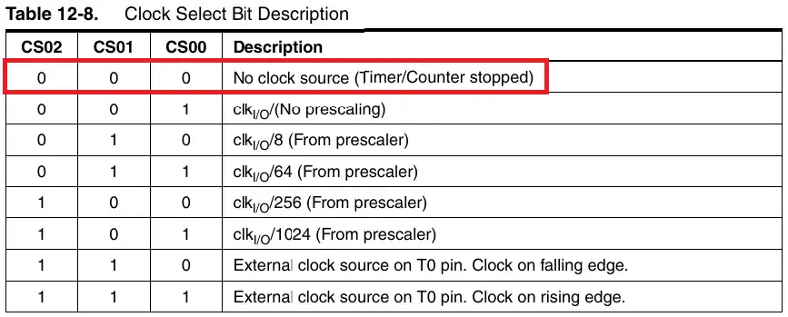
- When the value of the maindata is 0, we stop the timer and reset the counter.
The timer can be stopped by writing 0 to the bits, that are used to select the prescaler. To reset the counter, we can simply write the value 0 to the counter register, TCNT0.
Send String
We sent a single character in the previous function. To send an entire string, we just need to call the function (uart_char) as many times as there are characters in the string.
void uart_str (char *str)
{
	while (*str)
	{
		uart_char(*str++);
		while (maindata != 0);
	}
}
The parameter of the function is the character pointer. As long as there is some character data in the string, the function uart_char is called repeatedly. With each call the pointer is incrementing, so that it can point to the next character.
After sending each character, we wait for the maindata to become 0, so that we don’t send the next character while the previous character is still being transmitted.
The main function
char datatosend [] = "hello world from AVR\n";

int main(void)
{
	DDRB = 0x01;  // PB0 as output
	PORTB = 1<<PB0;  // Set PB0 HIGH
	timer_init();
    while(1)
    {
		uart_str(datatosend);
		_delay_ms(1000);
    }
}
We define the data to be sent as a character array.
- In the main function first define the PB0 as the output by configuring the DDRB register.
- Make sure to set the pin PB0 as HIGH. This is important, as the START bit is only recognized, once the data pin transits from HIGH to LOW.
- Initialize the timer.
- Now send the data every second in a while loop.
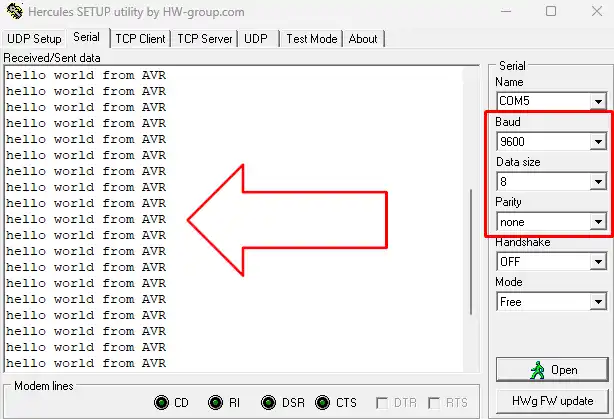
Result
I am using a USB to TTL module, so the data can be seen on the computer. The pin PB0 is connected to the RX pin of the Module.
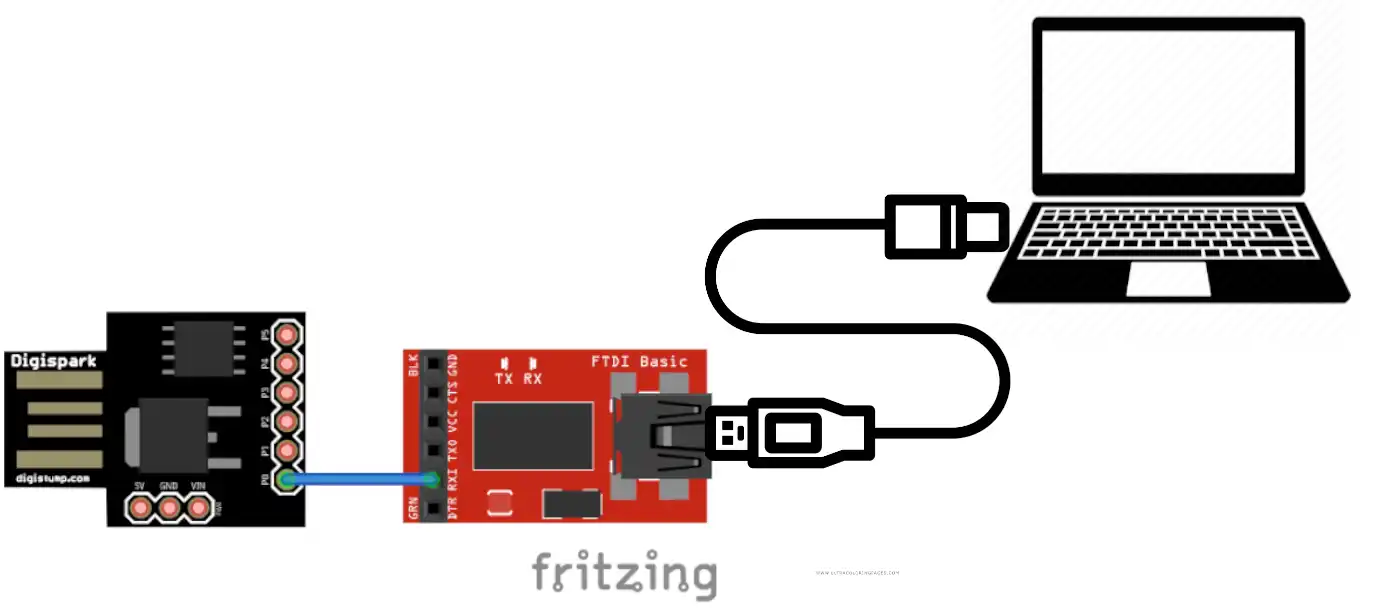
Below the picture shows the output on the serial terminal. You can see the data is received by the terminal as a serial data.