Updated On: April 24, 2026
STM32 Mongoose with W5500 – Ethernet on Any STM32 MCU
In this tutorial, we will integrate the Mongoose networking library with the W5500 SPI-to-Ethernet module on an STM32F446RE microcontroller. This is useful because the STM32F446 — and most F4 and F1 series MCUs — do not have a built-in Ethernet PHY. The W5500 brings full Ethernet capability over SPI, and Mongoose already has built-in support for it.
We will create the project in STM32 CubeIDE, generate the web UI using the Mongoose wizard targeting an Arduino W5500 project, and then port it over to STM32. The final result is a live web dashboard where we can control two LEDs and read a real-time ADC value from a potentiometer.
This is Part 7 of the STM32 TCP/IP with Mongoose series. Other parts of this series are listed below:
- STM32 TCP/IP with Mongoose: Complete Setup Guide
- STM32 HTTP Webserver using Mongoose
- STM32 Weather Station using Mongoose
- STM32 OTA Firmware Update using Mongoose
- STM32 Real-Time Graph using Mongoose
- STM32 Fixed Memory Pool for Networking using Mongoose
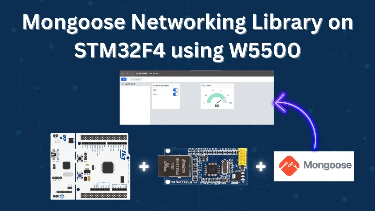
Table Of Contents
How Mongoose Works with W5500 on STM32
Before jumping into the code, it helps to understand what we are doing and why.
Why Use W5500 Instead of Built-In Ethernet
STM32 boards with a built-in Ethernet MAC — like the STM32H745 or STM32F746 — can use Mongoose directly with very little setup. But most of the popular, low-cost STM32 boards like the Nucleo F446RE or the STM32F103 Bluepill do not have Ethernet hardware on board.
The W5500 solves this. It is a hardwired TCP/IP controller that communicates over SPI and handles most of the network stack internally. All we need to do is connect it over SPI and send commands to it. This makes Ethernet available on virtually any STM32 MCU with a free SPI peripheral.
How Mongoose Talks to the W5500
Mongoose has built-in W5500 support. It communicates with the module through three SPI functions:
spi_begin()— pulls the CS pin LOW to start a transactionspi_end()— pulls the CS pin HIGH to end a transactionspi_txn()— transmits one byte and returns the received byte
These three functions are declared as extern inside the mongoose_config.h file. We need to define them using the STM32 HAL SPI functions. Once we do that, Mongoose takes care of everything above — TCP/IP, HTTP, WebSocket, DHCP — without any further changes.
The Porting Strategy — Arduino to STM32
The Mongoose wizard does not directly support W5500 on STM32 at the time of writing. However, it does support W5500 on Arduino. So the approach we take is:
- Create the STM32 CubeIDE project manually with all peripherals configured
- Generate the Mongoose wizard project targeting Arduino + W5500
- Copy the generated Mongoose files into the CubeIDE project
- Replace Arduino-specific headers and implement the SPI driver using STM32 HAL
This is a one-time porting step and it is straightforward once you know what to change.
W5500 Wiring and CubeMX Setup
Hardware Connections
The W5500 module connects to the STM32F446RE over SPI1. The module runs on 3.3V, which the Nucleo board provides directly.
The image below shows the complete wiring diagram for this project.

The connections are as follows:
- W5500 → STM32F446RE (SPI1)
- MOSI → PA7
- MISO → PA6
- SCLK → PA5
- CS → PB6
- RST → PC7
- 3.3V and GND from Nucleo board
- Potentiometer → PA0 (ADC1 Channel 0)
- LED 1 → PA1
- LED 2 → PA4
CubeMX Configuration
Open STM32CubeMX and create a new project for the STM32F446RE. As I mentioned earlier, we need to create a complete project in the CubeMX first, and then integrate mongoose later using the WebUI.
Here we will configure the SPI1 for the W5500, UART2 to print the logs on the serial console, ADC1 for the potentiometer and the 2 GPIO pins to connect the LEDs.
SPI1 Configuration
Enable SPI1 in Full-Duplex Master mode. The MOSI, MISO, and CLK pins are configured automatically. Set the data size to 8 bits, bit order to MSB first, and adjust the prescaler so the baud rate is around 10 Mbps.

Also configure PB6 as a GPIO output pin for CS and PC7 as a GPIO output pin for the Reset. Give them meaningful names — CS and RESET — for readability.
UART2 Configuration
We will use UART2 for the Virtual COM Port. This will be used for printf-based debug logging. The image below shows the UART2 Configuration.

ADC1 Configuration
Enable ADC1 and select Channel 0 (pin PA0). The default 12-bit resolution is fine.

GPIO Configuration
Configure two output pins for the LEDs — PA1 and PA4. The pins must be configured as the GPIO Output pins.

That is all we need to configure in the STM32CubeMX, Generate the project and import it into STM32 CubeIDE.
Mongoose Dashboard – Designing the UI
With the STM32 project ready, we now design the web dashboard using the Mongoose wizard. Since the wizard does not support W5500 on STM32 directly, we select the nearest equivalent — an Arduino board with W5500.
Create a new project, select Any Arduino board + W5500 Ethernet module, and choose the LED Toggle dashboard as the starting template.
Creating the LED and ADC Dashboard
The default dashboard already includes a container with two LED toggle buttons — this matches our two LEDs on the STM32, so we keep it as is.

Now, add a new container and name it ADC Data. Add a gauge element inside. This gauge will display the ADC value mapped to a range of 0 to 100. Add ticks with a gap of 20 between each tick, so the gauge shows 0, 20, 40, 60, 80, 100.

Creating the ADC REST API Endpoint
The LED endpoint is already present with two boolean attributes for the two LEDs. We need to add a new endpoint for the ADC data.
Create a new data endpoint called adc with a single integer attribute (value). Mark this endpoint as read-only — the MCU sends ADC values to the dashboard, and the dashboard never writes anything back.

The wizard will auto-generate a struct and getter function for this in mongoose_glue.c:
struct adc {
  int value;
};Now go to the Page Content tab and assign the API variables to the UI elements:
leds.led1andleds.led2→ the two LED toggle buttonsadc.value→ the ADC gauge

Configuring WebSocket Updates
To update the gauge in real time, we enable WebSocket in the UI settings. Later in the code, we will use the Websocket to send data to the gauge every 100 milliseconds.
The image below shows the Websocket configuration in the mongoose Web UI dashboard settings page.

Generate the project. This creates an Arduino project, but we will copy and adapt the files into our CubeIDE project.
Porting Mongoose to STM32 – Code & Results
This is where the actual work happens. We will first get the skeleton firmware running, then add Mongoose, implement the SPI driver, and finally wire up the REST API functions.
Creating the Skeleton Firmware
Before adding Mongoose, we need a minimal working firmware that has printf support and a working millisecond timer. Mongoose uses both of these internally.
Open main.c. Add the stdio.h include at the top. Then add a custom _write function to redirect printf to UART2:
int _write(int fd, unsigned char *buf, int len) {
  if (fd == 1 || fd == 2) {                     // stdout or stderr ?
    HAL_UART_Transmit(&huart2, buf, len, 999);  // Print to the UART
  }
  return len;
}Add the mg_millis() function, which Mongoose calls to get the current time in milliseconds:
uint64_t mg_millis(void)
{
return HAL_GetTick();
}Add a test printf inside the while loop:
while (1)
{
printf("Tick: %lu\n", HAL_GetTick());
HAL_Delay(500);
}This prints the uptime to the serial console every 500ms. If you can see this printing correctly, the clock and UART are both working fine.
The image below shows the expected output on the serial console.
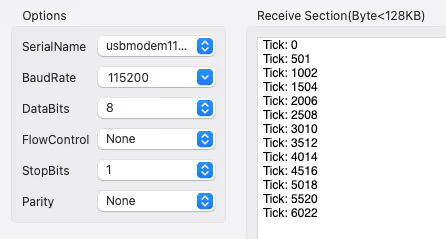
The uptime value should be incrementing every 500ms as shown. Once you see this, the skeleton firmware is ready and we can move on to integrating Mongoose.
Remove the test printf before moving on.
Adding Mongoose to the CubeIDE Project
Open the Arduino project generated by the Mongoose wizard. Inside the project folder, you will find the Mongoose source files.
In CubeIDE, go to the Drivers folder and create a new folder called Mongoose. Copy all the wizard-generated files into this folder.
The image below shows the CubeIDE project structure after adding the Mongoose folder.

Now open mongoose_config.h and make the following changes:
Replace the Arduino header:
// Remove this:
#include <Arduino.h>
// Add this instead:
#include "main.h"The architecture will already be set to custom and W5500 support will already be enabled — the wizard handles that. If you want a static IP, uncomment and set the IP defines here.
// For static IP configuration, define MG_TCPIP_{IP,MASK,GW}
// By default, those are set to zero, meaning that DHCP is used
//
//#define MG_TCPIP_IP MG_IPV4(192, 168, 1, 10)
//#define MG_TCPIP_GW MG_IPV4(192, 168, 1, 1)
//#define MG_TCPIP_MASK MG_IPV4(255, 255, 255, 0)We will use DHCP, so we leave those commented out.
Build the project. You will see around 470 errors at this point. This is expected — we just need to add three standard headers that Arduino includes automatically but STM32 does not:
#include <stdlib.h>
#include <stdbool.h>
#include <string.h>Add these to mongoose_config.h alongside the main.h include. Build again.
Now only few errors remain. These are related to Arduino’s millis() function, which Mongoose uses for timekeeping. We already defined mg_millis() ourselves, so we just need to tell Mongoose to use it. Add this to mongoose_config.h:
#define MG_ENABLE_CUSTOM_MILLIS 1Build again — zero errors. Mongoose is now successfully integrated with STM32.
Now add the Mongoose folder to the compiler include paths. Go to Project Properties → C/C++ Build → Settings → Compiler Include Paths and add the path to the Mongoose folder.

Save and rebuild to confirm there are no include errors.
Implementing the SPI Driver for W5500
Open the mongoose_config.h file and find the three SPI functions — spi_begin(), spi_end(), and spi_txn(). Copy these into main.c and rewrite them using the STM32 HAL:
void spi_begin(void *spi) {
(void) spi;
HAL_GPIO_WritePin(CS_GPIO_Port, CS_Pin, GPIO_PIN_RESET);
}
void spi_end(void *spi) {
(void) spi;
HAL_GPIO_WritePin(CS_GPIO_Port, CS_Pin, GPIO_PIN_SET);
}
uint8_t spi_txn(void *spi, uint8_t byte) {
uint8_t rbyte = 0;
HAL_SPI_TransmitReceive(&hspi1, &byte, &rbyte, 1, 100);
(void) spi;
return rbyte;
}spi_beginpulls CS LOW to select the W5500.spi_endpulls it HIGH to deselect it.spi_txnsends one byte over SPI and returns the byte received at the same time — this is full-duplex SPI in action. Thehspi1instance is the one generated by CubeMX as we are using SPI1 here.
With these three functions in place, Mongoose has everything it needs to communicate with the W5500.
Now add the W5500 reset sequence and Mongoose initialization inside main(), after the peripheral initializations:
/* Reset W5500 */
HAL_GPIO_WritePin(RESET_GPIO_Port, RESET_Pin, GPIO_PIN_RESET);
HAL_Delay(10);
HAL_GPIO_WritePin(RESET_GPIO_Port, RESET_Pin, GPIO_PIN_SET);
HAL_Delay(10);
/* Initialize Mongoose */
mongoose_init();Add mongoose_poll() inside the while loop:
while (1)
{
mongoose_poll();
}Build and flash. Open the serial console. You should see Mongoose initializing, the W5500 driver starting up, the HTTPS listener activating, and a DHCP-assigned IP address appearing in the logs.
The image below shows the serial console output with Mongoose initialized and an IP address assigned via DHCP.

Copy the IP address and open it in a browser. The dashboard loads — the UI is live. The REST API endpoints are not connected yet, so the elements will not respond, but this confirms the basic Mongoose setup is working.
Writing the Getter, Setter and ADC Functions
Open mongoose_glue.c and find the auto-generated getter and setter functions. We should not edit this file directly because it will be overwritten if you regenerate the project. Instead, we define renamed versions in main.c.
LED setter — called when a toggle button is pressed on the UI:
void my_set_leds(struct leds *data)
{
HAL_GPIO_WritePin(GPIOA, GPIO_PIN_1, data->led1);
HAL_GPIO_WritePin(GPIOA, GPIO_PIN_4, data->led2);
}LED getter — called when the UI loads to read the current LED state:
void my_get_leds(struct leds *data)
{
data->led1 = HAL_GPIO_ReadPin(GPIOA, GPIO_PIN_1);
data->led2 = HAL_GPIO_ReadPin(GPIOA, GPIO_PIN_4);
}For the ADC, we first write a helper function that reads ADC1 and maps the 12-bit result to a 0–100 range:
long map(long x, long in_min, long in_max, long out_min, long out_max)
{
return (x - in_min) * (out_max - out_min + 1) / (in_max - in_min + 1) + out_min;
}
int adc_read (void)
{
HAL_ADC_Start (&hadc1);
HAL_ADC_PollForConversion(&hadc1, 100);
uint16_t adc_val = HAL_ADC_GetValue(&hadc1);
HAL_ADC_Stop(&hadc1);
return (map(adc_val, 0, 4095, 0, 100));
}Then write the ADC getter that the Mongoose framework will call:
void my_get_adc(struct adc *data)
{
data->value = adc_read();
}The raw ADC value is 12-bit (0–4095). We scale it to 0–100 so the gauge on the dashboard shows a clean percentage-style reading.
Registering HTTP Handlers and WebSocket Reporter
After mongoose_init(), register the HTTP handlers for both endpoints and set up the WebSocket reporter:
mongoose_init();
mongoose_set_http_handlers("adc", my_get_adc, NULL);
mongoose_set_http_handlers("leds", my_get_leds, my_set_leds);
mongoose_add_ws_reporter(100, "adc");The LED endpoint has both a getter and a setter. The ADC endpoint only has a getter — NULL is passed for the setter since the UI never writes to it. The WebSocket reporter pushes ADC data every 100 milliseconds, which keeps the gauge updating smoothly in real time.
Make sure the endpoint names — "leds" and "adc" — exactly match what you defined in the Mongoose wizard.
Full Code
Here is the complete set of additions made to main.c:
#include "stdio.h"
#include "mongoose_glue.h"
/* ---- printf redirect ---- */
int _write(int fd, unsigned char *buf, int len) {
  if (fd == 1 || fd == 2) {                     // stdout or stderr ?
    HAL_UART_Transmit(&huart2, buf, len, 999);  // Print to the UART
  }
  return len;
}
/* ---- Mongoose timekeeping ---- */
uint64_t mg_millis(void)
{
    return HAL_GetTick();
}
/* ---- SPI Driver for W5500 ---- */
void spi_begin(void *spi) {
	(void) spi;
	HAL_GPIO_WritePin(CS_GPIO_Port, CS_Pin, GPIO_PIN_RESET);

}

void spi_end(void *spi) {
	(void) spi;
	HAL_GPIO_WritePin(CS_GPIO_Port, CS_Pin, GPIO_PIN_SET);

}

uint8_t spi_txn(void *spi, uint8_t byte) {
	uint8_t rbyte = 0;
	HAL_SPI_TransmitReceive(&hspi1, &byte, &rbyte, 1, 100);
	(void) spi;
	return rbyte;
}
/* ---- ADC Helper ---- */
long map(long x, long in_min, long in_max, long out_min, long out_max)
{
return (x - in_min) * (out_max - out_min + 1) / (in_max - in_min + 1) + out_min;
}
int adc_read (void)
{
HAL_ADC_Start (&hadc1);
HAL_ADC_PollForConversion(&hadc1, 100);
uint16_t adc_val = HAL_ADC_GetValue(&hadc1);
HAL_ADC_Stop(&hadc1);
return (map(adc_val, 0, 4095, 0, 100));
}
/* ---- LED Getter ---- */
void my_get_leds(struct leds *data)
{
data->led1 = HAL_GPIO_ReadPin(GPIOA, GPIO_PIN_1);
data->led2 = HAL_GPIO_ReadPin(GPIOA, GPIO_PIN_4);
}
/* ---- LED Setter ---- */
void my_set_leds(struct leds *data)
{
HAL_GPIO_WritePin(GPIOA, GPIO_PIN_1, data->led1);
HAL_GPIO_WritePin(GPIOA, GPIO_PIN_4, data->led2);
}
/* ---- ADC Getter ---- */
void my_get_adc(struct adc *data)
{
data->value = adc_read();
}
/* ---- Inside main() ---- */
/* Initialize peripherals */
MX_GPIO_Init();
MX_SPI1_Init();
MX_USART2_UART_Init();
MX_ADC1_Init();
/* USER CODE BEGIN 2 */
/* Reset W5500 */
HAL_GPIO_WritePin(RESET_GPIO_Port, RESET_Pin, GPIO_PIN_RESET);
HAL_Delay(10);
HAL_GPIO_WritePin(RESET_GPIO_Port, RESET_Pin, GPIO_PIN_SET);
HAL_Delay(10);
/* Initialize Mongoose and register handlers */
mongoose_init();
mongoose_set_http_handlers("adc", my_get_adc, NULL);
mongoose_set_http_handlers("leds", my_get_leds, my_set_leds);
mongoose_add_ws_reporter(100, "adc");
while (1)
{
    mongoose_poll();
}Output
Serial Console
After flashing, open the serial console. Mongoose will initialize, the W5500 driver will start, and a DHCP-assigned IP address will appear in the logs.
The image below shows the serial console output — Mongoose initialized and IP address assigned.
Web UI Dashboard
Open the IP address in a browser. The dashboard loads with the two LED toggle buttons and the ADC gauge.
The image below shows the Mongoose web dashboard loaded on the STM32F446 with W5500.

LED Test: Press the toggle buttons on the dashboard — the LEDs on the board respond immediately. Toggle them off and they turn off. This confirms the getter and setter functions are working correctly.
The GIF below shows the LEDs responding to the web UI toggle buttons.

ADC Test: Rotate the potentiometer. The gauge on the dashboard updates in real time, showing values from 0 to 100 as the pot moves from one end to the other.
The image below shows the ADC gauge updating as the potentiometer is rotated.

Both elements are working correctly. The Mongoose library is fully running on the STM32F446RE using the W5500 SPI Ethernet module.
STM32 Mongoose with W5500 SPI Ethernet — Video Tutorial
This video walks through the complete integration of the Mongoose networking library with the W5500 SPI Ethernet module on STM32F446. We port the Mongoose wizard Arduino project to CubeIDE, implement the SPI driver, and build a live web dashboard with LED control and a real-time ADC gauge.
Download STM32 Mongoose W5500 Project Files
Complete CubeIDE project for STM32F446 with W5500 SPI Ethernet, Mongoose integration, LED control, and ADC gauge dashboard. Free to download — support the work if it helped you.
STM32 Mongoose W5500 — Frequently Asked Questions
Conclusion
In this tutorial, we integrated the Mongoose networking library with the W5500 SPI Ethernet module on an STM32F446RE. Since Mongoose does not directly support W5500 on STM32 through the wizard, we used the Arduino W5500 project as a starting point and ported it over to CubeIDE by replacing the Arduino headers and implementing the three SPI functions using the STM32 HAL.
The key takeaway here is that once the SPI driver is in place — just three functions — Mongoose handles everything else. TCP/IP, HTTP, WebSocket, DHCP, the web dashboard, all of it works out of the box. This means you can bring Mongoose to any STM32 that has a free SPI peripheral, even the smaller F1 and F4 series boards that have no built-in Ethernet.
The ADC gauge and LED controls both worked as expected, with the gauge updating live via WebSocket every 100 ms. This is a good foundation for more complex dashboards — you can add more sensors, more controls, and more endpoints on top of the same structure.
Browse More STM32 Mongoose TCP/IP Tutorials
STM32 Web Server using Mongoose: HTTP, WebSocket & ADC Dashboard
STM32 Weather Station Web Server using Mongoose (Ethernet + BME280)

STM32 OTA Firmware Update using Mongoose – Step by Step Guide
STM32 Real-Time Graph using Mongoose Ethernet
STM32 Fixed Memory Pool for Networking using Mongoose and O1heap
STM32 Modbus TCP Server – Read Input Registers with Mongoose
STM32 Modbus TCP Server – Read Discrete Inputs with Mongoose


Thank you for your articles, definitely the best ones about STM32 stuff on the internet.
Very important note :
For newer Mongoose versions >= 7.21, they have changed the definition of the spi_txn function to send multiple bytes at the same time !
Here is a replacement function that is working perfectly :
void spi_txn(void *, uint8_t *write, uint8_t *read, size_t size) {
    if(write == NULL){
        HAL_SPI_Receive(&hspi1, read, size, 100);
    }else if (read == NULL){
        HAL_SPI_Transmit(&W5500_SPI, write, size, 100);
    }else{
        HAL_SPI_TransmitReceive(&W5500_SPI, write, read, size, 100);
    }
}
Note that the distinction between tx/rx and txrx is important because Mongoose will just put NULL in the receive/transmit buffer address if they don’t use it which makes HAL_SPI_TransmitReceive return HAL_ERROR.
I have been stuck on this for multiple days because, the log was just showing a driver init error without any detail, and no compile time error…