Home ▸ STM32 Tutorials ▸
Updated On: March 23, 2026
How to use LVGL on Riverdi STM32-H7 based Display
This is yet another tutorial on the Riverdi STM32 Embedded display series. Today we will cover the 7″ STM32-H7 based display, but instead of using the TouchGFX, we will use the LVGL.
Using LVGL has its own advantages like its comparatively Lightweight, and we can regenerate the project after editing it in the cubeMX, which has been an issue for the Riverdi displays while using the TouchGFX.
In today’s tutorial, we will see how to implement the LVGL on this 7″display. We will build the UI using the Squareline studio, then use the cubeMX to configure a PWM output pin whose signal will vary based on the slider movement on the UI.
VIDEO TUTORIAL
You can check the video to see the complete explanation and working of this project.
Implement the LVGL
Riverdi has released some Repositories containing the LVGL implementation on its different displays. We will download the one for the 7″ display from their github https://github.com/riverdi/riverdi-70-stm32h7-lvgl. We also need to download the LVGL version 8.3 from https://github.com/lvgl/lvgl/tree/release/v8.3.
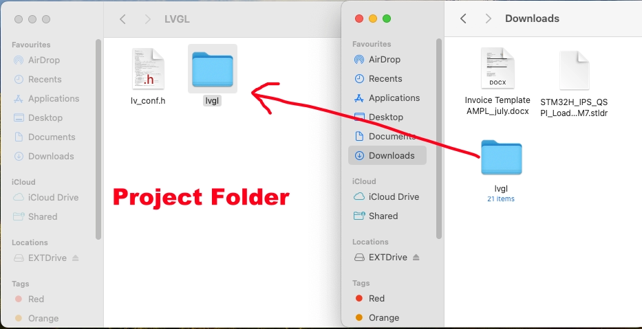
The lvgl directory in the project is located in the Project Folder -> Middleware -> Third_Party -> LVGL, but it is empty. We need to copy the lvgl directory we downloaded to this location.
Make sure to rename the downloaded lvgl_8.3 directory to “lvgl” before copying.
Now we will import the project in the cube IDE. The project structure is shown below.
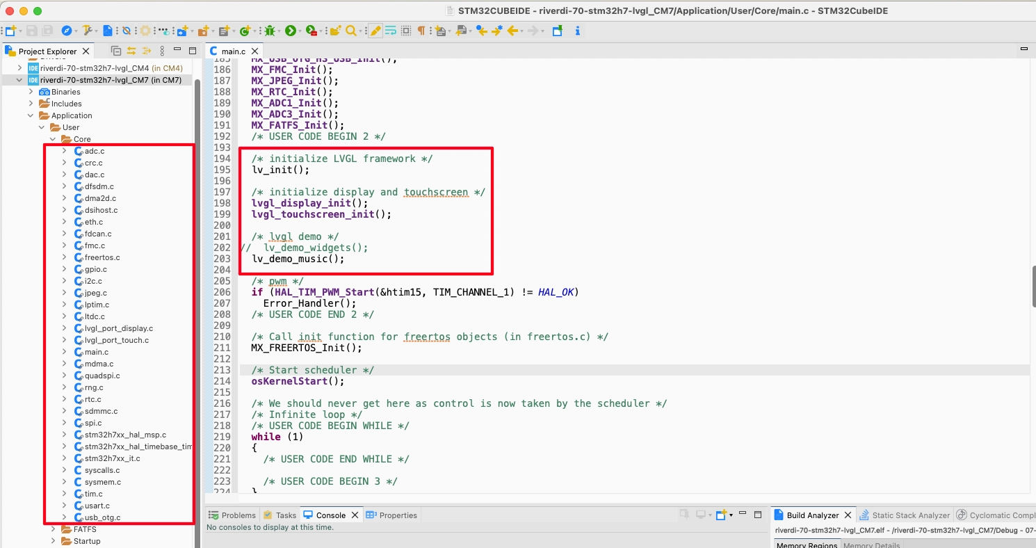
As you can see just like the other Riverdi projects we have seen, here also all the peripherals are pre-initialised. In the main file after all the initialisation is finished, the LVGL initialisation begins.
I haven’t modified anything yet and this is the default setup we get in the project. The lvgl music demo is being initialised in the default project. When we will load the default project to the board we should see the music demo playing.
Build the code does result in few warning, but there is no error. Although there is no Debug/Run configuration provided in the default project. So we need to create a new configuration to flash the project to the board.
Click on Run -> Run Configuration.
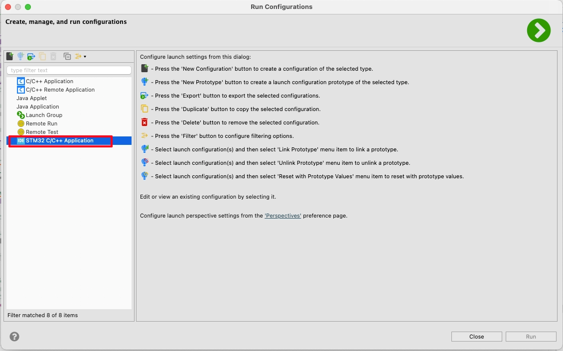
You can see in the above picture that there is no configuration present in the project. Double click on STM32 C/C++ Application to create a new configuration.
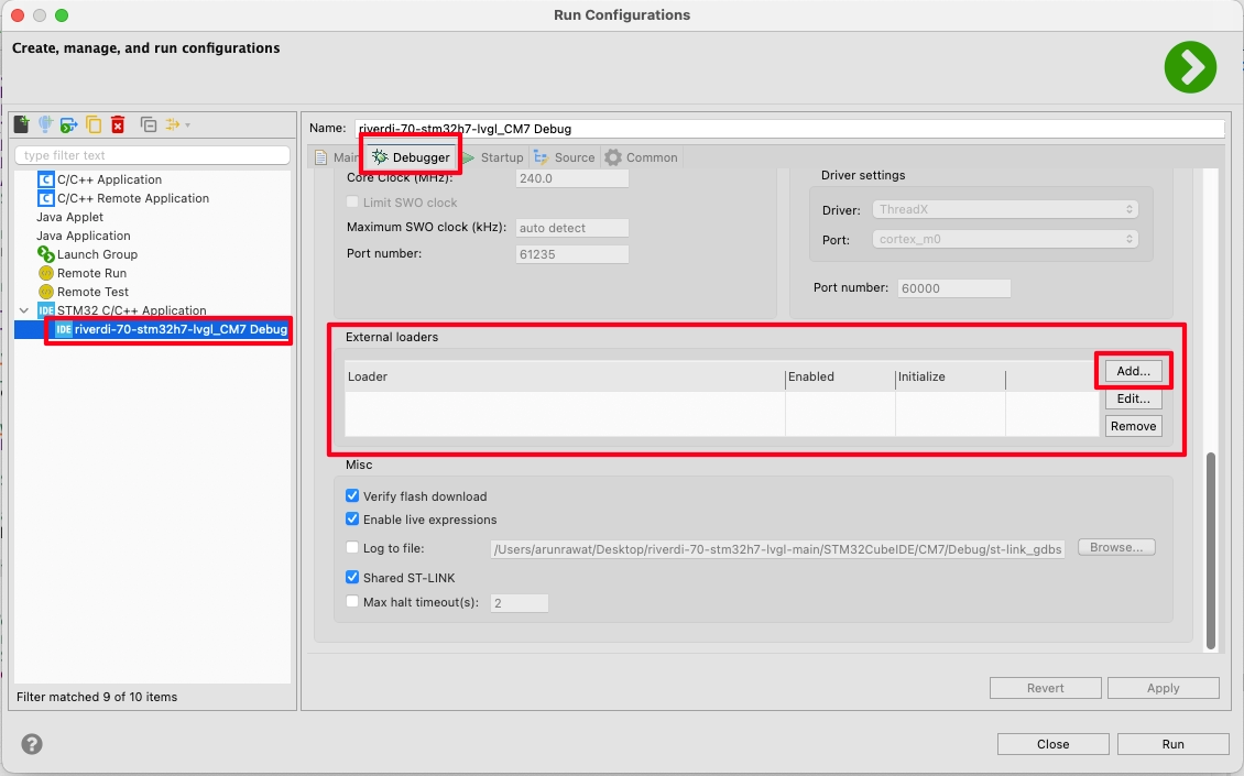
Click on the generated configuration, go to Debugger tab and scroll down to External Loader. Here you can see that the external loader is not present in the configuration. Actually the same MCU (STM32H757XIH86) is used across the 10.1″ and 7″ displays with the same QuadSPI memory. So we can use the same External Loader for all these displays.
You can download the loader from https://drive.google.com/file/d/1gUB85dc3E_Zvk4OEqkr0zDT_mvIauKXg/view?usp=sharing. Copy it inside the project folder.
Now click on add button and locate the loader.
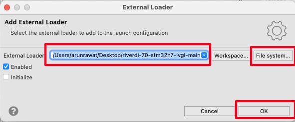
Once the loader is located, click OK. Then click Run to flash the project to the board with this configuration.
Below is the gif showing the music demo on the display.

So we have implemented the LVGL on the Riverdi 7″ STM32-H7 based display. Now we will build some UI and use it in a practical way.
Build UI using Squareline Studio
Click on Create, select Desktop and then select the Eclipse on PC.
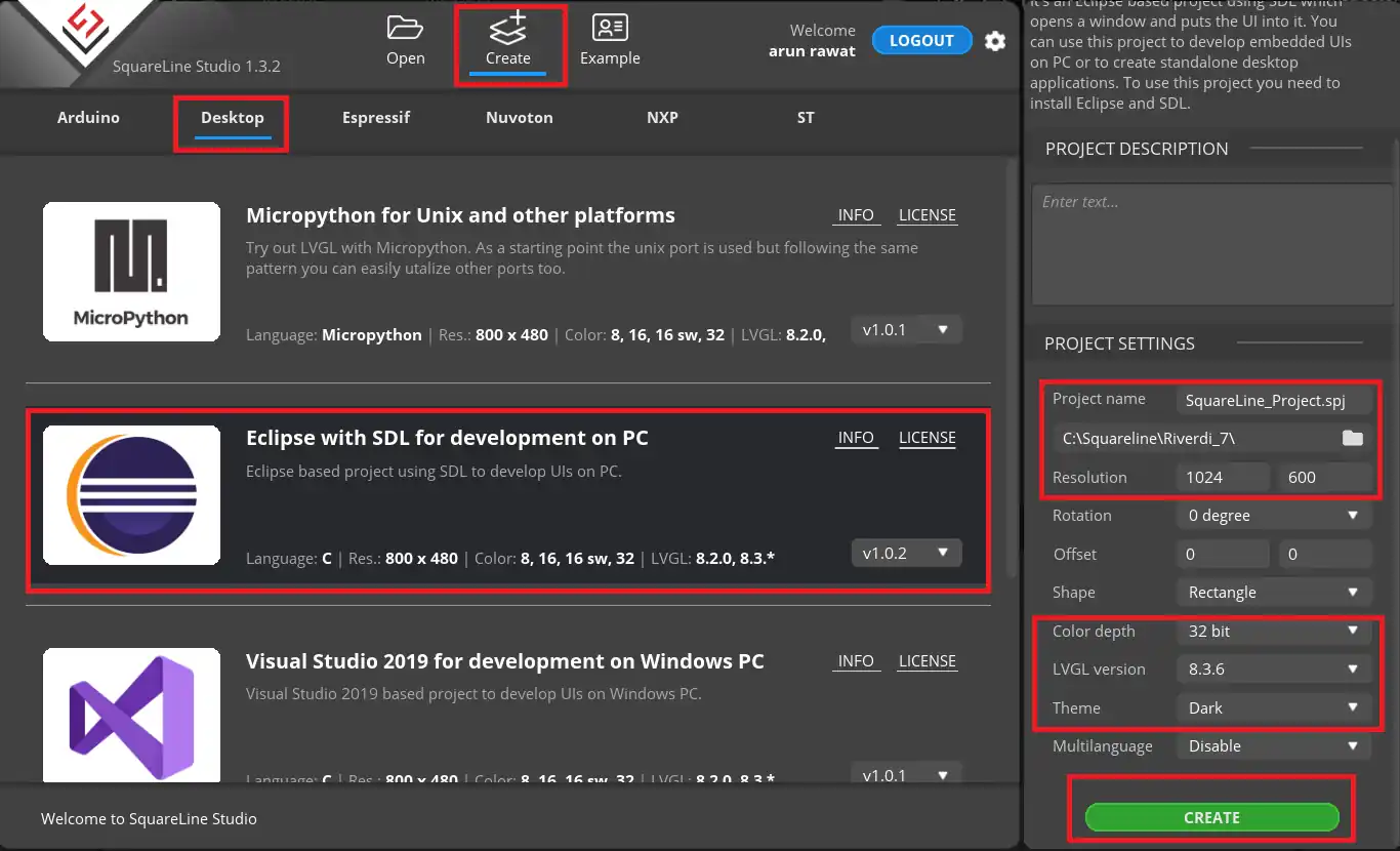
On the Right side, choose the project folder and give the project name.
- The screen Resolution is set to 1024 x 600 Pixels.
- Color depth is 32 bit.
- LVGL version is the same we downloaded, i.e 8.3.6
- I am choosing the dark theme for the screen
Click create to create the Project.
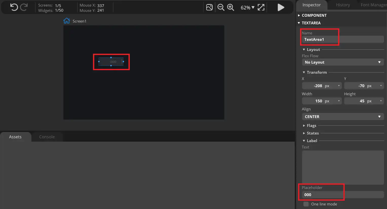
I am adding a text area to show the slider’s value. The placeholder is set to “000”.
Now add a slider to the UI.
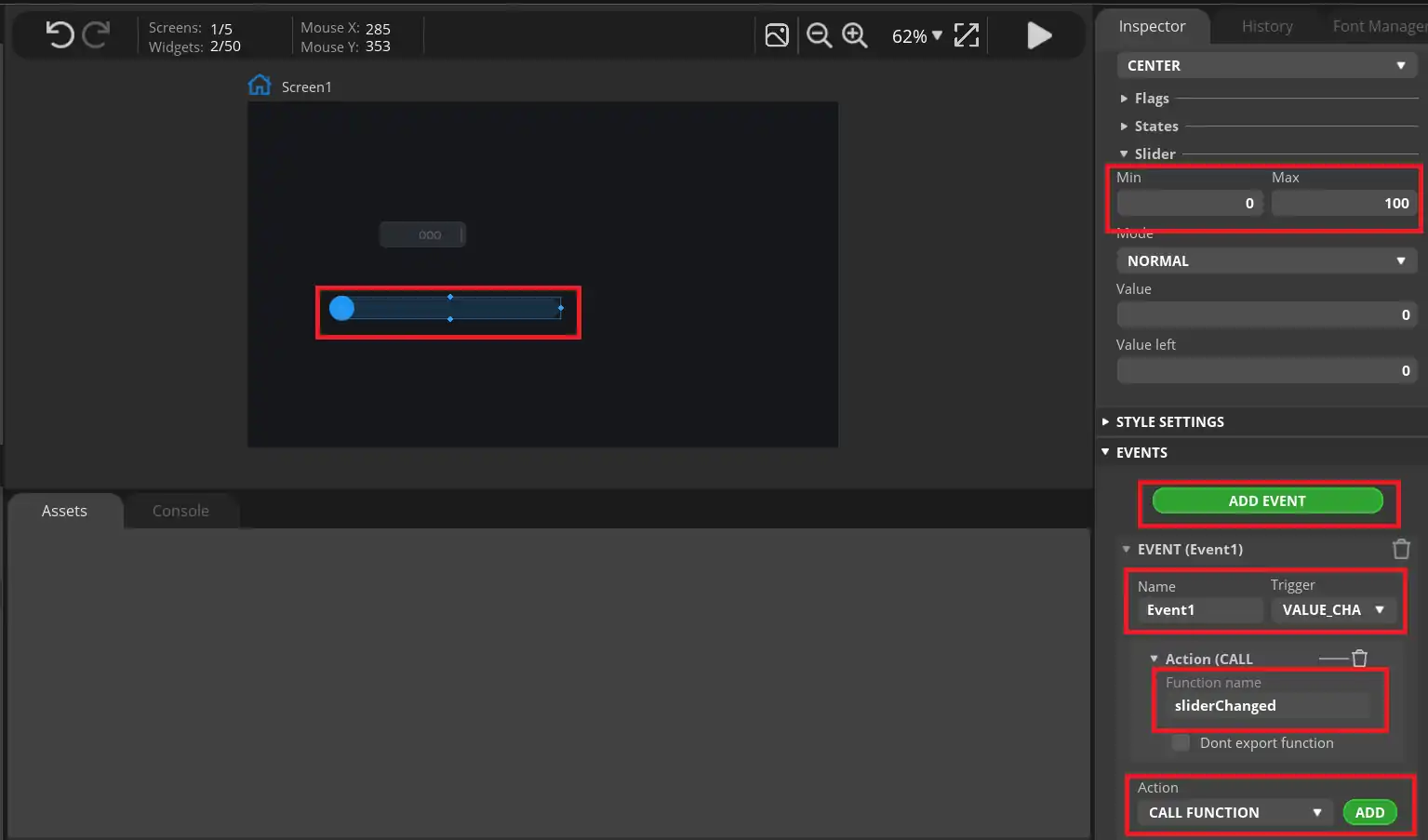
The Slider range is set to 0 to 100. We will also add an event to the slider which will trigger when the slider value is changed.
Here we will call a function, sliderChanged, which we will write in the IDE itself.
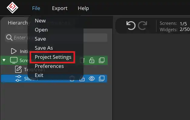
Now click on File and click Project Settings.
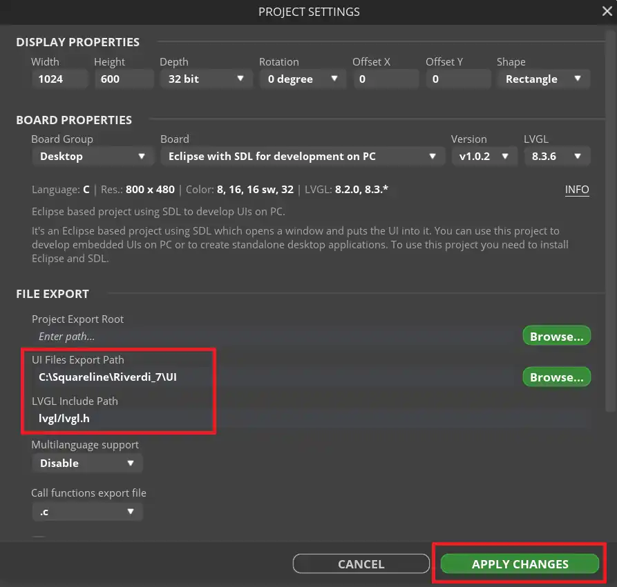
Set the UI file export path, where the exported UI files will be saved. Also set the lvgl include path to lvgl/lvgl.h.
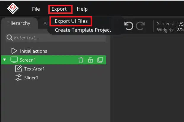
Now click on Export and export Ui files.
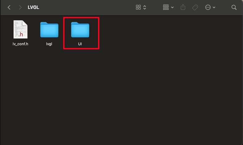
The UI files will be exported in the folder we defined earlier in the project settings. Copy this folder inside the project folder. I am copying it beside the lvgl directory.
CubeMX Configuration
Below is the pinout shown for the expansion connector.
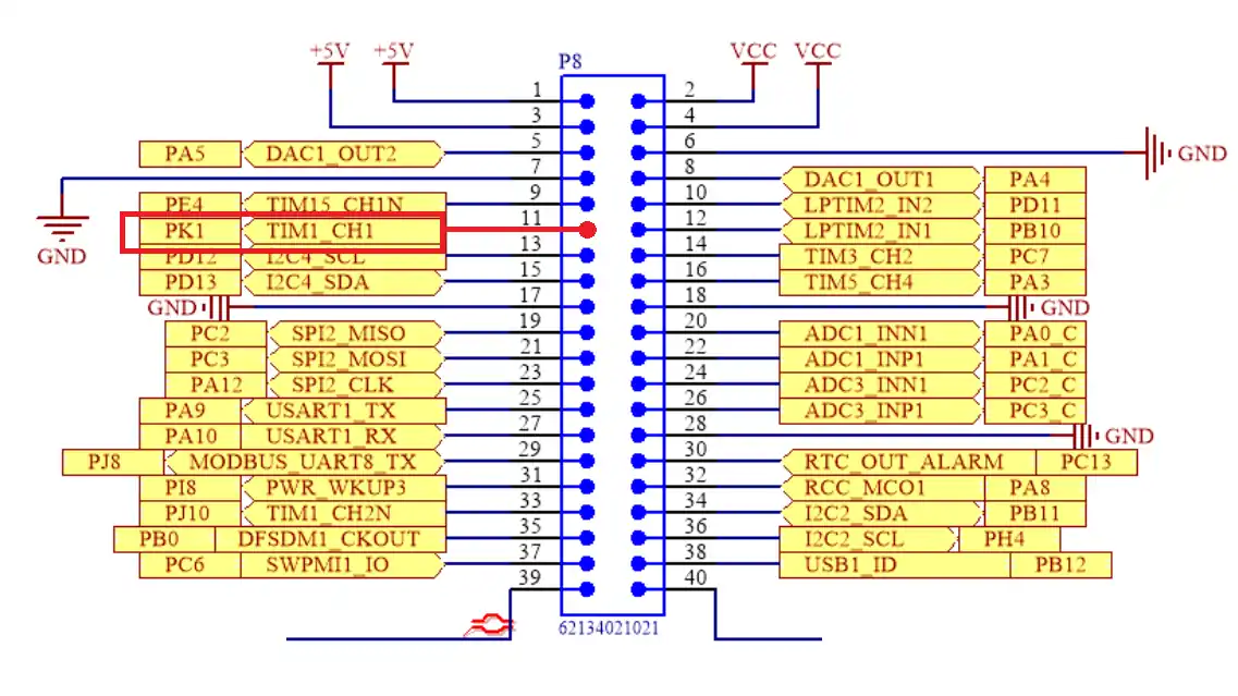
I am going to use the Timer 1 Channel 1 for the PWM output. This is the pin 11 on the expansion connector.
We will configure the PWM in the cubeMX.
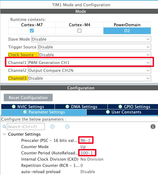
The channel 1 is already configured in the PWM output mode. The Timer 1 clock is connected to the APB1 which is at 240 MHz.
Using the prescaler of 96 will bring down the clock to 240/96 = 2.5MHz. The Auto Reload value (ARR) of 100 will further reduce the clock to 2.5MHz/100 = 25KHz.
Generate the project to save the configuration.
Let’s write the code
#include "UI/ui.h"

  /* initialize LVGL framework */
  lv_init();

  /* initialize display and touchscreen */
  lvgl_display_init();
  lvgl_touchscreen_init();

  ui_init ();

HAL_TIM_PWM_Start(&htim1, TIM_CHANNEL_1);In the main file, we will first include the UI header file. The after initialising the lvgl, initialise the UI and the Timer in the PWM mode.
When the slider’s value is changed, the function sliderChanged will be called. This function is defined in the ui_event.c file inside the UI folder.
char buf[4];

void sliderChanged(lv_event_t * e)
{
	int value = lv_slider_get_value(ui_Slider1);
	sprintf (buf, "%d", value);
	lv_textarea_set_text(ui_TextArea1, buf);
	TIM1->CCR1 = value;
}Inside this function we will set the value to different components.
- We will first read the slider’s value and then store it in the variable value.
- Then convert the integer value to the character format using the sprintf.
- Set the character buffer to the text area so that it can display the slider’s value.
- Also set the integer value to the Capture Compare Register (CCR1) of the timer 1.
The slider have a range of 0 to 100 and the ARR is also set to 100. This means the slider’s value can directly act as the duty percentage of the PWM signal.
Result
Below is the image showing the PWM signal on the logic analyser along with the slider on the display.
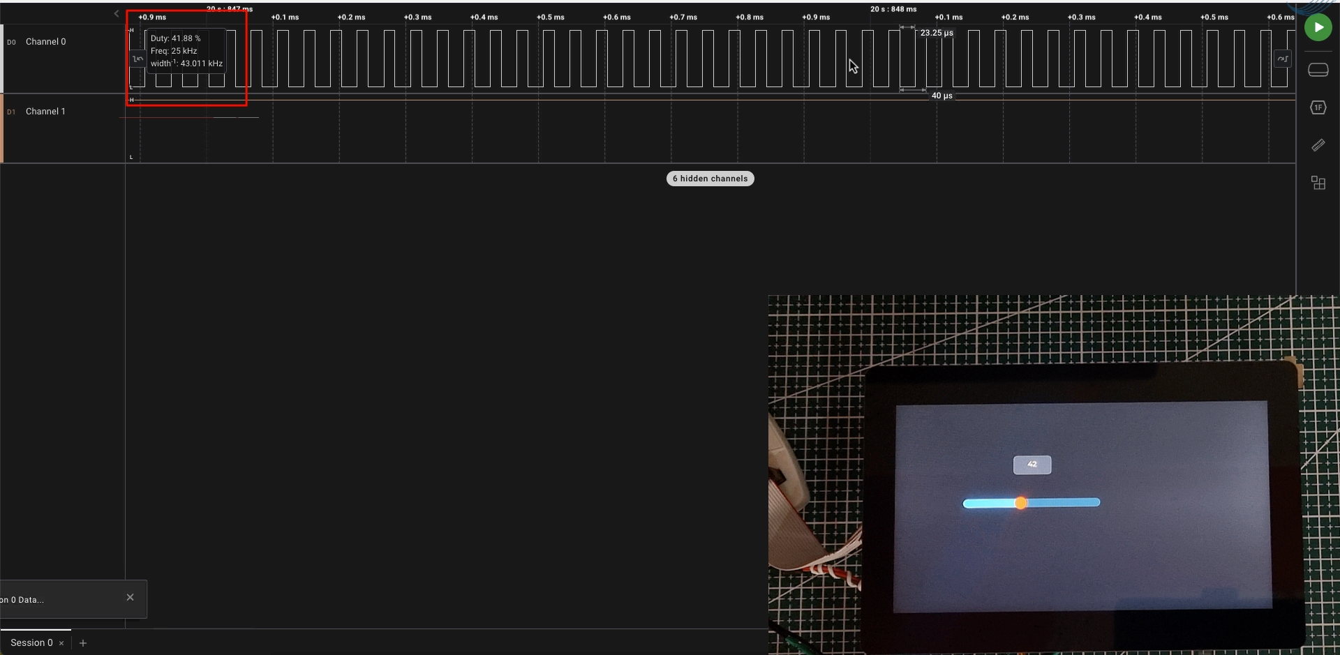
You can see in the image above that the duty shown on the logic software is same as the slider’s value set on the display.
Below is the gif showing the brightness variation of the LED based on the slider’s movement.

The brightness of the LED depends on the voltage on it. The output voltage varies from 0 to 3.3V with the slider’s value ranging from 0 to 100.
STM32 LVGL Tutorial Series
LVGL on STM32 || PART 2
LVGL on STM32 || PART 4
LVGL ON STM32 || PART5
LVGL on STM32 || PART 6
LVGL on STM32 || PART7 || Load LVGL from Ext Flash
STM32 GC9A01 Round Display: SPI & LVGL Integration Guide
STM32 Analog Clock on GC9A01 — LVGL, SquareLine Studio & RTC


Hi
Nice presentation
How to store images in qspi, when using LVGL and STM32H7
coming soon