Interface STONE HMI Display with STM32
In this tutorial we will see how to interface the Stone HMI Display with STM32. We will control a LED connected to the STM32 using the buttons on the display, also we will print the potentiometer value on the display.
For this tutorial I am going to use the STM32F103C8 controller. The HMI Displays generally communicates using the UART, so in order to control the display, all we need is a controller with UART peripheral, which is actually very common to find.
Let’s start with the connection
The Connection
The Stone HMI Display have the connector header in order to connect to the microcontrollers. But the spacing between the pins is too wide, and I couldn’t find any male header which can fit it. The display comes along with a USB-UART board which can also be used to power the display.
After doing some continuity testing I have found that the pins of this USB-UART board can also use used as the TX and RX pins. The diagram for the same is shown below
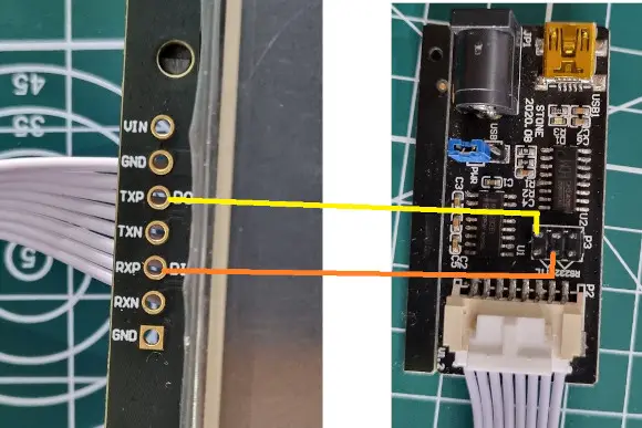
The HMI Display communicates in the RS232 format and in order to convert it to the TTL, I am using a RS232 to TTL converter.
The MCU is connected to the display via this converter as shown below.

Note that between the MAX232 converter and the USB-UART board, there is a cross connection, TX->RX and RX->TX. But between the MCU and MAX232 converter, there is a straight connection, TX->TX and RX->RX.
The MAX232 needs to be supplied 5V, as it will misbehave at 3.3V.
Also the potentiometer is connected to the Pin PA0 (ADC Pin), and we have a LED connected to the pin PB12.
The Design
Below is the image from the Stone designer including all the elements used in the Design.
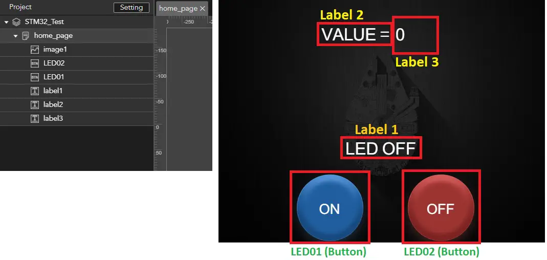
There are 3 Labels
- Label 1 indicates the LED State
- Label 2 have the fixed string, “VALUE =”, and it does not change
- Label 3 is going to be updated with the value from the potentiometer
There are 2 buttons, LED01 is the ON button and we will program it to turn ON the LED. LED02 is the OFF button and it will turn the LED OFF.
The CubeMX configuration is pretty simple. All we need to do is enable the UART, ADC and Set the LED pin to output
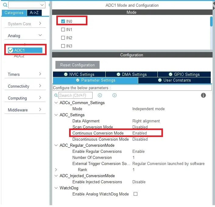
Here I have enabled the ADC1 Channel 0. Everything can be kept as default, but I have just enabled the continuous conversion mode.
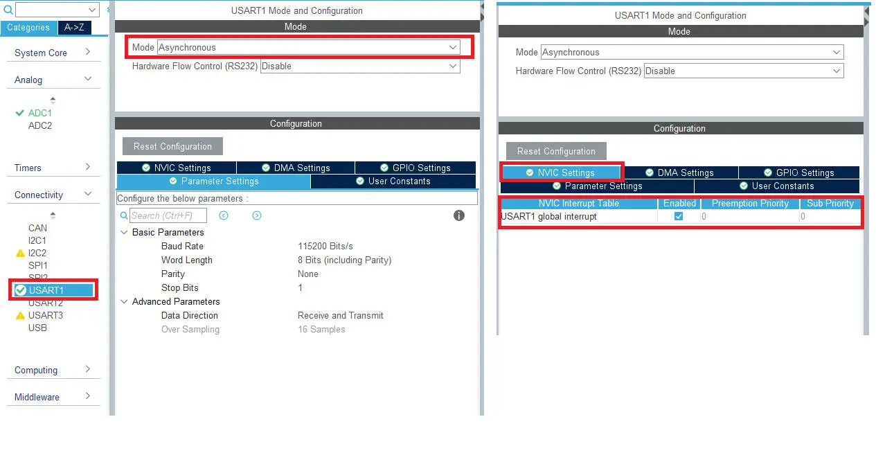
Here I have enabled the USART1 in asynchronous mode. Again everything should be kept to default, specially the baud rate must be 115200. Just enable the UART interrupt in the NVIC tab.
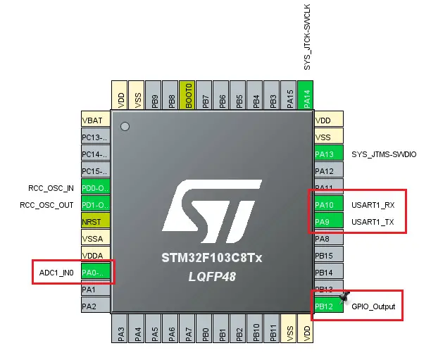
Above is the image of the final pinout of the STM32F103C8. We have 2 pins for the USART, 1 ADC channel 0 pin, and PB12 is set as GPIO output. This is where the LED is going to be connected.
The Code
On Pressing the button on the display, it sends the data via the UART. The data sent by the HMI Display is shown below:
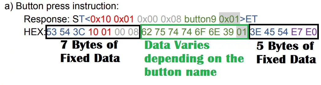
Basically we get the 12 bytes of fixed data, and the rest depends on what name have we set for the button. As per this tutorial, I have set the button names as LED01 and LED02, so the total data sent by the display would be 12 Bytes + 5 Bytes for button name + 1 byte for the value = 18 Bytes.
We can write a simple UART receive function to receive 18 bytes of data, and then check for the button name in the received data.
But just to make it more convenient, I am going to use another function, HAL_UARTEx_ReceiveToIdle_IT(&huart1, RxData, 50);
This function triggers the interrupt whenever the Idle line is detected in the input. This means when the MCU does not receive data for a fixed amount of time, the interrupt gets triggered and the received data will be stored in the RxData Buffer.
void HAL_UARTEx_RxEventCallback(UART_HandleTypeDef *huart, uint16_t Size)
{
	isreceived = 1;
	HAL_UARTEx_ReceiveToIdle_IT(&huart1, RxData, 50);
}
Inside the interrupt handler, we set the isreceived variable to 1, and we call the same function again. This is because the HAL disables the interrupt after one call and therefore we need to call it again.
This isreceived variable set to 1 will be used in the while loop. This basically confirms that we have received some data, and the rest of the processing will be done in the while loop.
if (strncmp((char *)(RxData+7), "LED01", 5) == 0)
{
 HAL_GPIO_WritePin(GPIOB, GPIO_PIN_12, GPIO_PIN_SET);
 isreceived = 0;
 TxData = (char *)malloc(100);
 int len = sprintf(TxData, "ST<{\"cmd_code\":\"set_text\",\"type\":\"label\",\"widget\":\"label1\",\"text\":\"LED ON\"}>ET");
 HAL_UART_Transmit(&huart1, (uint8_t *)TxData, len, 1000);
 free(TxData);
}
- In the while loop we check if the received data contains the string “LED01“, which is actually the name of the ON button
- Note that we are checking the button name from the 7th position, as I explained above that the first 7 bytes remains constant, so button name starts at 7th position itself.
- If the string is found, means that the ON button was pressed, we will proceed further.
- Here we will first Set the LED pin HIGH.
- Then reset the isreceived variable to 0, so that we don’t enter the same loop again.
- Then send the text “LED ON” to the label 1 indicating that the LED is ON.
In order to send the text to the label, we used the command given in the instruction manual of the display. Below is the image from the manual showing this command.

The sprintf is just used to copy the string to the TxData buffer, which is then sent via the UART.
Similar to ON button, we also check for the OFF button, and then proceed accordingly. Below is the full code related to the buttons.
if (isreceived)
{
	if (strncmp((char *)(RxData+7), "LED01", 5) == 0)
	{
	 HAL_GPIO_WritePin(GPIOB, GPIO_PIN_12, GPIO_PIN_SET);
         isreceived = 0;
         TxData = (char *)malloc(100);
         int len = sprintf(TxData, "ST<{\"cmd_code\":\"set_text\",\"type\":\"label\",\"widget\":\"label1\",\"text\":\"LED ON\"}>ET");
         HAL_UART_Transmit(&huart1, (uint8_t *)TxData, len, 1000);
         free(TxData);
        }

	else if (strncmp((char *)(RxData+7), "LED02", 5) == 0)
	{
	 HAL_GPIO_WritePin(GPIOB, GPIO_PIN_12, GPIO_PIN_RESET);
	 isreceived = 0;
	 TxData = (char *)malloc(100);
	 int len = sprintf(TxData, "ST<{\"cmd_code\":\"set_text\",\"type\":\"label\",\"widget\":\"label1\",\"text\":\"LED OFF\"}>ET");
	 HAL_UART_Transmit(&huart1, (uint8_t *)TxData, len, 1000);
	 free(TxData);
	}
}
We also need to send the potentiometer value to the display. The potentiometer is connected to the Pin PA0 (ADC Channel 0).
Since the requirement for the potentiometer is not very time critical, we can simply use the ADC with polling. Below is the code for the same.
HAL_ADC_Start(&hadc1);
HAL_ADC_PollForConversion(&hadc1, 100);
uint16_t val = HAL_ADC_GetValue(&hadc1);
HAL_ADC_Stop(&hadc1);

TxData = (char *)malloc(100);
int len = sprintf(TxData, "ST<{\"cmd_code\":\"set_text\",\"type\":\"label\",\"widget\":\"label3\",\"text\":\"%u\"}>ET", val);
HAL_UART_Transmit(&huart1, (uint8_t *)TxData, len, 1000);
free(TxData);

HAL_Delay(100);- Here we start the ADC, The Poll for conversion, then get the value and finally stop the ADC.
- Now to transfer the value to the Display, we use the similar method to what we used in the buttons.
- We need to convert the ADC value to the string format and that’s why the use of format identifier, %u, is needed.
- Once the value has been converted to string format, it gets stored in the TxData buffer along with the rest of the command.
- We finally send this data via the uart.
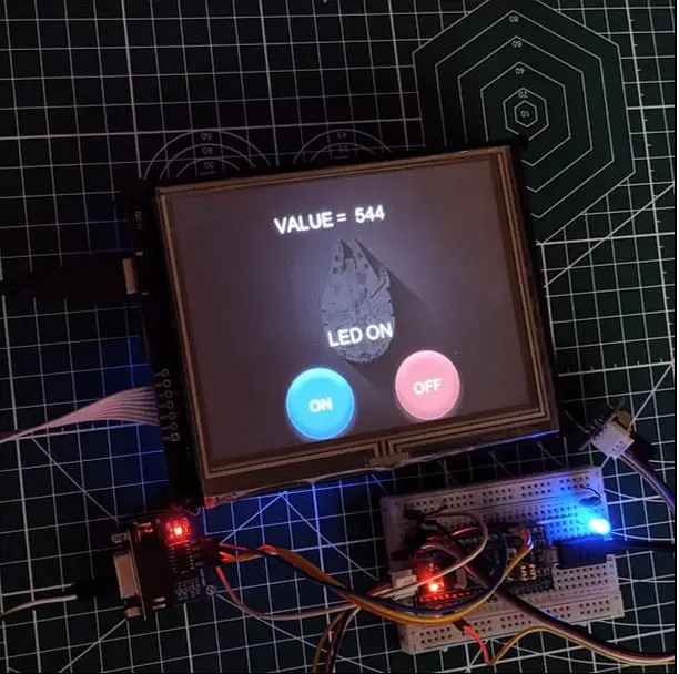
Result
Below are some images showing the LED, it’s state and the potentiometer value.

[/vc_column_text][/vc_column][vc_column width=”1/4″ offset=”vc_hidden-sm vc_hidden-xs”][vc_column_text]