
Updated On: April 16, 2026
STM32 OTA Firmware Update using Mongoose Ethernet
In this tutorial, we will implement STM32 OTA firmware updates using the Mongoose Networking library. Mongoose handles all the heavy lifting — the HTTP transfer, the file reception, and the flashing. We just need to set up the web UI and write a few lines of code.
We will build two projects:
- Project 1: A minimal OTA interface used as the base firmware
- Project 2: A full application with LED and backlight control + OTA
We will first flash Project 1 onto the board, then use it to flash Project 2 over the air. This is a real OTA scenario.
This tutorial is Part 4 of the STM32 TCP/IP with Mongoose series. I have also covered several other tutorials based on the Mongoose TCP/IP on STM32. These projects demonstrate different features such as HTTP server, WebSocket communication, and embedded web UI.
You can explore them below:
- STM32 TCP/IP with Mongoose: Complete Setup Guide
- STM32 HTTP Webserver using Mongoose
- STM32 Weather Station using Mongoose

Table Of Contents
- What is STM32 OTA Update?
- STM32 OTA Project Overview
- Project 1 – STM32 OTA with Simple Web Interface
- Project 2 – STM32 OTA with LED and Backlight Control
- STM32 OTA Update – Result
- STM32 OTA Firmware Update using Mongoose — Video Tutorial
- Download STM32 OTA Firmware Update (Mongoose) Project Files
- STM32 OTA Firmware Update using Mongoose – Frequently Asked Questions
What is STM32 OTA Update?
OTA (Over-The-Air) update is a method of updating the firmware on a microcontroller remotely over a network. Instead of using a physical programmer like ST-Link, we send the new firmware as a binary file over Ethernet or Wi-Fi. The device receives the file, writes it to flash memory, and reboots with the new firmware.
This is very useful in production environments. Imagine deploying 50 STM32 boards in a factory. Updating each one physically would take hours. With OTA, you update all of them from a browser in minutes.
Why use Mongoose for STM32 OTA?
Mongoose makes STM32 OTA straightforward. It provides a built-in OTA mechanism that handles the entire update process. We do not need to write a custom bootloader or manage flash sectors manually. Mongoose handles the complete OTA pipeline:
- Receives the firmware binary via HTTP upload
- Writes it to the inactive flash bank
- Verifies the write operation
- Switches the boot bank and reboots the device
The Mongoose dashboard wizard also auto-generates the REST API and the web UI element for OTA. So there is very little manual work involved.
How Mongoose Performs the OTA – Bank Switching
STM32 devices such as the STM32H7 series support dual-bank flash, which enables safe OTA updates.
The update process works as follows:
- The current firmware runs from Bank 1
- During OTA, the new firmware is written to Bank 2
- Once the update is complete and verified, the boot configuration is switched to Bank 2
- The device reboots and starts executing the new firmware
This approach ensures reliability — if the update fails, the original firmware remains intact.
STM32 OTA Project Overview
We will build two separate STM32 projects in this tutorial. Both projects use Mongoose for Ethernet communication and OTA firmware updates. The goal is to first flash Project 1 onto the board, and then use its OTA interface to flash Project 2 — demonstrating a real over-the-air update scenario.
Project 1 – Simple OTA Interface
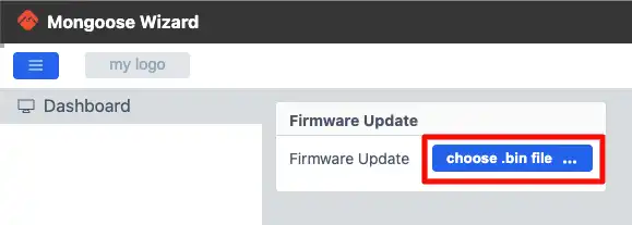
Project 1 is a minimal web interface. It has a single panel with one element — the OTA firmware update button. We use this project as the base firmware running on the board. From its web interface, we will upload and flash the Project 2 binary over the air.
The image below shows the web UI for Project 1.
Project 2 – OTA with LED and Backlight Control
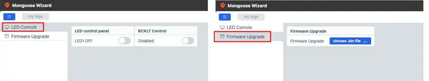
Project 2 is a more complete application. It has two pages:
- Page 1 – Controls the onboard LED and the display backlight using toggle buttons.
- Page 2 – Contains the OTA firmware update button, same as Project 1.
This project demonstrates that we can build a full-featured application on top of Mongoose and still retain OTA update capability. We will flash this project onto the board via OTA from Project 1.
The image below shows the web UI for Project 2.
Project 1 – STM32 OTA with Simple Web Interface
Project 1 is the starting point. We will flash this project onto the STM32 board first. It runs a lightweight web server using Mongoose and exposes a simple OTA firmware update interface. We will later use this interface to flash Project 2 over the air.
Creating the Web UI
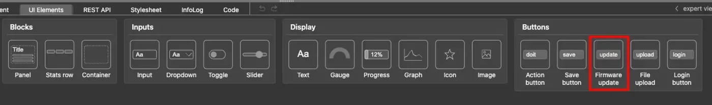
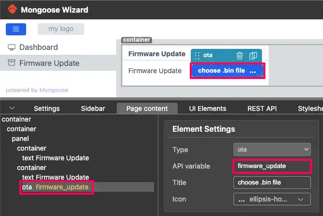
We use the Mongoose dashboard wizard to create the web UI. The interface for Project 1 has a single panel with one element — the Firmware Update button. We add this element from the UI components panel in the wizard.
The image below shows the Firmware Update element added in the Mongoose wizard.
The wizard automatically generates the REST API for this element. The API name is firmware_update and the type is ota.
The image below shows the auto-generated REST API for the OTA button.
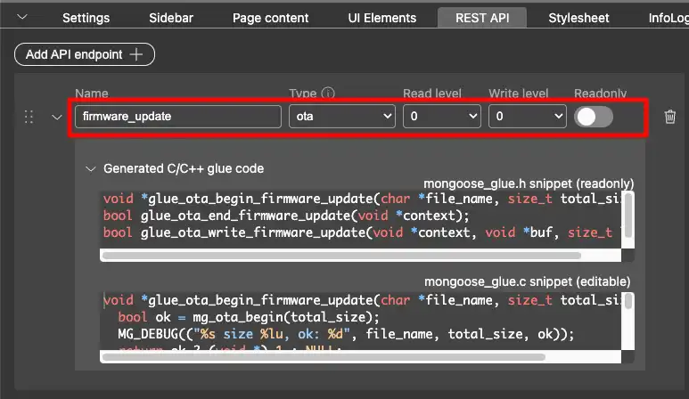
We do not need to modify anything here. Once the element is added, we generate the project from the wizard.
The image below shows the final web UI for Project 1.
Enabling Binary File Generation in STM32CubeIDE
By default, STM32CubeIDE does not generate a .bin file after a build. We need to enable this manually. We will use this binary file later to flash Project 2 via OTA.
To enable it, go to:
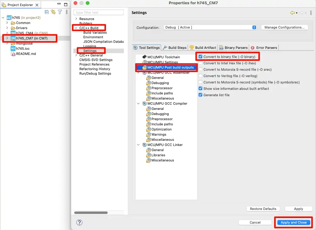
Project Properties → C/C++ Build → Settings → Post Build Outputs
Enable the binary file generation option as shown in the image below.
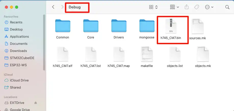
After building the project, the .bin file will appear in the project → Debug folder.
The image below shows the generated binary file in the Debug folder.
Static IP Configuration for STM32
After importing the project into the IDE, we need to test it to make sure everything is configured correctly.
By default, Mongoose uses DHCP to assign an IP address. Since I am connecting the Ethernet cable directly to the PC, there is no DHCP server on the network. So we need to configure a static IP manually.
Open the Mongoose configuration file mongoose_config.h and uncomment the static IP definitions. Set the IP address, gateway, and subnet mask based on your PC’s network settings. For example:
#define MG_TCPIP_IP   MG_IPV4(192, 168, 0, 10)
#define MG_TCPIP_GW   MG_IPV4(192, 168, 0, 1)
#define MG_TCPIP_MASK MG_IPV4(255, 255, 255, 0)You need to manually set your computer’s Ethernet adapter to be in the same subnet as the static IP.
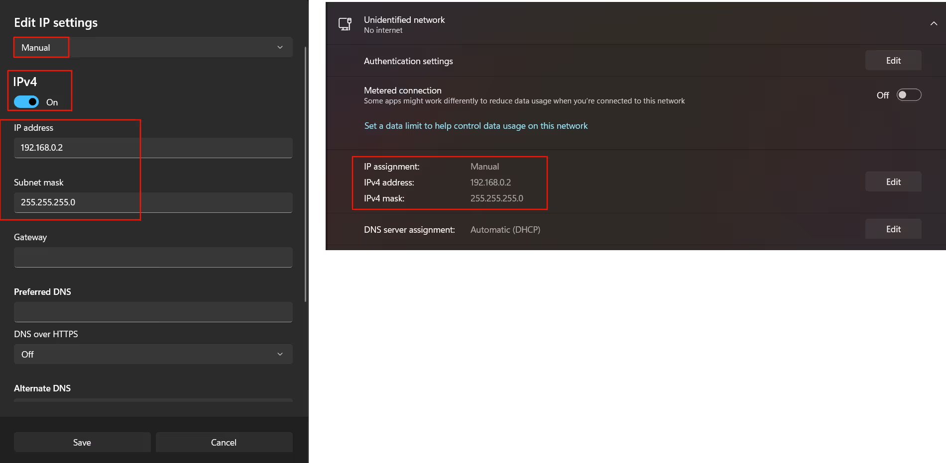
On Windows:
The image below shows the IPv4 settings for a Windows computer.
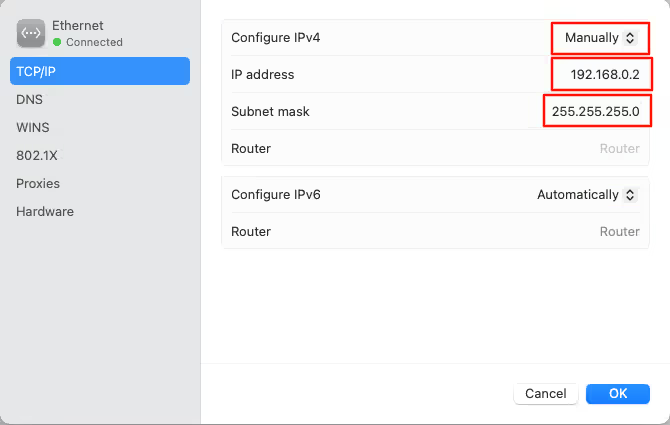
On Mac:
The image below shows the network settings on a Mac.
Make sure the IP address you assign to the STM32 is in the same subnet as your PC. For example, if your PC’s IP is 192.168.0.5, the STM32 should be something like 192.168.0.10.
Output
We flash Project 1 onto the board and check the serial console. The board will show the IP address on the console — in our case 192.168.0.10. We open this IP in a browser and the OTA web interface loads.
The image below shows the serial console logs after flashing Project 1.

The image below shows Project 1 running in the browser.

Project 2 – STM32 OTA with LED and Backlight Control
Project 2 is a more complete application. It adds LED and display backlight control on top of the OTA functionality. We will build this project, generate the binary, and flash it onto the board via OTA from Project 1.
Creating the Web UI
The web UI for Project 2 has two pages. Page 1 contains toggle buttons to control the onboard LED and the display backlight. Page 2 contains the OTA firmware update button.
The image below shows the complete web UI for Project 2.
Page 1 – LED and Backlight Control
For the LED toggle, the text field displays the current LED state using the API variable leds.state. We use the following expression:
${leds.state ? 'ON' : 'OFF'}If leds.state is 1, it shows ON. Otherwise it shows OFF.
The image below shows the LED control panel configuration in the wizard.
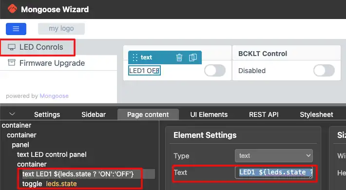
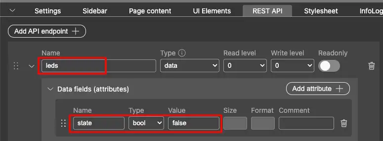
The REST API for the LED toggle uses the endpoint leds.
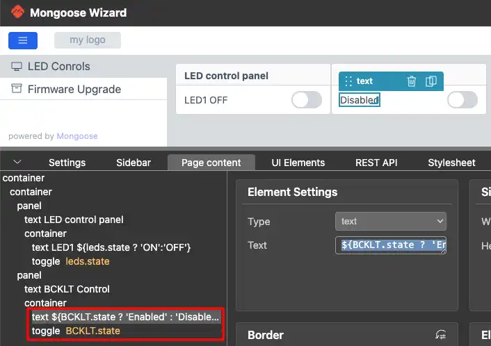
For the Backlight toggle, the text field displays the state using the API variable BCKLT.state. We use the following expression:
${BCKLT.state ? 'Enabled' : 'Disabled'}If BCKLT.state is 1, it shows Enabled. Otherwise it shows Disabled.
The image below shows the Backlight control panel configuration in the wizard.
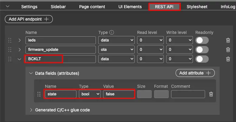
The REST API for the Backlight toggle uses the endpoint BCKLT.
Page 2 – OTA Firmware Update
Page 2 contains only the OTA firmware update element. The API variable firmware_update is assigned automatically by the wizard. We do not need to modify anything here.
The image below shows the OTA element on Page 2.
Once both pages are configured, we generate the project from the wizard.
GPIO Configuration in STM32CubeMX
We need to configure two GPIO pins for Project 2 — one for the LED and one for the display backlight.
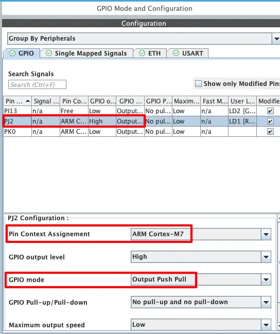
LED Pin – PJ2
The onboard LED is connected to pin PJ2. We configure this pin as a GPIO output. Since we are using a dual-core STM32 board, we also assign this pin to the Cortex-M7 core.
The image below shows the configuration for pin PJ2.
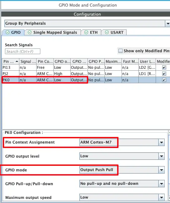
Backlight Pin – PK0
The display backlight is connected to pin PK0. We configure this pin as a GPIO output as well.
The image below shows the configuration for pin PK0.
LED and Backlight Control Code
Mongoose auto-generates getter and setter functions in the mongoose_glue.c file. However, this file regenerates every time we update the Mongoose dashboard. So we write our custom getter and setter functions in main.c instead.
LED Getter and Setter Functions
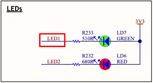
The LED is connected between 3.3V and pin PJ2. This means:
- When PJ2 is Reset → LED turns ON
- When PJ2 is Set → LED turns OFF
We handle this in the getter and setter functions as shown below.
void my_get_leds(struct leds *data) {
  if (HAL_GPIO_ReadPin(GPIOJ, GPIO_PIN_2)) data->state = false;  // If the pin is HIGH, LED is OFF
  else data->state = true;  // LED is ON
}

void my_set_leds(struct leds *data) {
  if (data->state) HAL_GPIO_WritePin(GPIOJ, GPIO_PIN_2, GPIO_PIN_RESET);  // turn LED ON
  else HAL_GPIO_WritePin(GPIOJ, GPIO_PIN_2, GPIO_PIN_SET);  // turn LED OFF
}The my_get_leds function reads pin PJ2 and updates data->state accordingly. If the pin is set, the LED is OFF, so we assign 0. Otherwise we assign 1.
The my_set_leds function writes to pin PJ2 based on data->state. If the state is 1, we reset the pin to turn the LED ON. If the state is 0, we set the pin to turn the LED OFF.
The image below shows the LED schematic on the dev board.
Backlight Getter and Setter Functions
The backlight behaves differently from the LED. It turns ON when PK0 is set and turns OFF when PK0 is reset. So we can directly pass data->state to the HAL functions.
void my_get_BCKLT(struct BCKLT *data) {
  data->state = HAL_GPIO_ReadPin(GPIOK, GPIO_PIN_0);
}

void my_set_BCKLT(struct BCKLT *data) {
  HAL_GPIO_WritePin(GPIOK, GPIO_PIN_0, data->state);
}Setting HTTP Handlers in Main
By default, Mongoose uses the functions generated in mongoose_glue.c. To make Mongoose use our custom functions, we register them using mongoose_set_http_handlers after mongoose_init().
/* USER CODE BEGIN 2 */
mongoose_init();
mongoose_set_http_handlers("leds", my_get_leds, my_set_leds);
mongoose_set_http_handlers("BCKLT", my_get_BCKLT, my_set_BCKLT);
for (;;) {
mongoose_poll();
}
/* USER CODE END 2 */The function mongoose_set_http_handlers takes three arguments:
- The API endpoint name (e.g.
"leds") - The getter function to call when the UI fetches the state
- The setter function to call when the UI sends a new state
Here is the complete code combining all the functions we wrote:
// Getter and Setter for LED
void my_get_leds(struct leds *data) {
if (HAL_GPIO_ReadPin(GPIOJ, GPIO_PIN_2)) data->state = false;
else data->state = true;
}
void my_set_leds(struct leds *data) {
if (data->state) HAL_GPIO_WritePin(GPIOJ, GPIO_PIN_2, GPIO_PIN_RESET);
else HAL_GPIO_WritePin(GPIOJ, GPIO_PIN_2, GPIO_PIN_SET);
}
// Getter and Setter for Backlight
void my_get_BCKLT(struct BCKLT *data) {
  data->state = HAL_GPIO_ReadPin(GPIOK, GPIO_PIN_0);
}

void my_set_BCKLT(struct BCKLT *data) {
  HAL_GPIO_WritePin(GPIOK, GPIO_PIN_0, data->state);
}
// Main
mongoose_init();
mongoose_set_http_handlers("leds", my_get_leds, my_set_leds);
mongoose_set_http_handlers("BCKLT", my_get_BCKLT, my_set_BCKLT);
for (;;) {
mongoose_poll();
}Enabling Binary File Generation in STM32CubeIDE
Just like Project 1, we need to enable binary file generation in STM32CubeIDE. Go to:
Project Properties → C/C++ Build → Settings → Post Build Outputs
Enable the binary file generation option as shown in the image below.
After building the project, the .bin file will appear in the project → Debug folder. We will use this binary to flash Project 2 via OTA.
STM32 OTA Update – Result
At this stage, Project 1 is already flashed onto the development board and the Mongoose web server is running successfully.
Flashing Project 2 via OTA from Project 1
To perform the OTA update, open the web interface in your browser and click on the OTA Firmware Update button. Select the project2.bin file that we generated earlier.

Once the upload starts, the firmware is transferred to the STM32 over Ethernet. You can monitor the entire process in the serial console, where Mongoose prints the update logs in real time.

After the upload and flashing process is completed successfully, the device will automatically reboot. On restart, the boot configuration switches to the updated firmware, and Project 2 is loaded and executed.
The image below shows Project 2 running on the development board after the OTA update.

The GIF below demonstrates the LED control functionality working in real time via the web interface.

STM32 OTA Firmware Update using Mongoose — Video Tutorial
This video walks through the complete implementation of OTA (Over-The-Air) firmware updates on STM32 using the Mongoose Ethernet library. We create a web-based OTA interface, generate the firmware binary, and demonstrate a real OTA workflow by flashing a new project over Ethernet — without using a programmer.
Download STM32 OTA Firmware Update (Mongoose) Project Files
Complete CubeMX projects for both OTA examples, including Mongoose configuration, web UI, and firmware binaries. Free to download — support the work if it helped you.
STM32 OTA Firmware Update using Mongoose – Frequently Asked Questions
Conclusion
In this tutorial, we implemented OTA (Over-The-Air) firmware updates on STM32 using the Mongoose Ethernet library. We started with a simple OTA interface in Project 1 and then used it to upload and flash a more advanced application (Project 2) over the network. Along the way, we configured the web UI using the Mongoose dashboard, enabled binary generation, set up static IP networking, and wrote custom handlers for controlling GPIO peripherals like the LED and display backlight.
This approach is extremely useful in real-world applications where devices are deployed in large numbers or in hard-to-access locations. Instead of relying on physical programmers, firmware can be updated remotely through a browser, saving significant time and effort. With Mongoose handling the networking and OTA process, you can focus on building your application while still having a reliable and scalable update mechanism in place.
Browse More STM32 Mongoose TCP/IP Tutorials

STM32 Web Server using Mongoose: HTTP, WebSocket & ADC Dashboard

STM32 Weather Station Web Server using Mongoose (Ethernet + BME280)

STM32 Real-Time Graph using Mongoose Ethernet
STM32 Fixed Memory Pool for Networking using Mongoose and O1heap
STM32 Mongoose with W5500 – Ethernet on Any STM32 MCU
STM32 Modbus TCP Server – Read Discrete Inputs with Mongoose
STM32 Modbus TCP Server – Read and Write Coils using Mongoose

Subscribe
Login
0 Comments
Newest
