
Home ▸ STM32 Tutorials ▸
Published: May 31, 2025
Last Updated: February 6, 2026
Last Updated: February 6, 2026
Implement STM32 OTA Updates using Mongoose
In this tutorial you will learn how to Implement OTA (Over‑The‑Air) firmware updates on STM32 using the Mongoose Ethernet library. You will also Learn setup, HTTP transfer, and safe flashing. The project is available to download at the end of this post.
In this tutorial, two projects will be developed. Project 1 features a simple user interface with a component dedicated to performing firmware updates. Project 2 includes a multi-page interface: Page 1 provides controls for managing LEDs on the STM32 development board, while Page 2 offers functionality for initiating firmware updates.
Recommended Resources:
This tutorial is a part of the STM32 Ethernet tutorial series. This is also the 4th tutorial in the mini series covering the implementation of the Mongoose Networking Library. The Previous tutorials in this mini series covered how to set up the Mongoose library on STM32, how to run a web-server on STM32 using this library and how to create a weather station on STM32.
You should take a look at the following tutorials before continuing here:
- STM32 Ethernet with Mongoose | Part 1 Setup Guide
- STM32 Ethernet with Mongoose | Part 2 Web Server
- STM32 Ethernet with Mongoose | Part 3 Weather Station
VIDEO TUTORIAL
You can check the video to see the complete explanation and working of this project.
Introducing STM32 Ethernet Peripheral
STM32 microcontrollers with built-in Ethernet MAC (Media Access Controller) enable high-speed wired communication, making them ideal for IoT, industrial automation, and real-time data transfer applications. By integrating Ethernet directly into the MCU, STM32 devices reduce the need for external network controllers, simplifying hardware design and reducing cost.
Below are some important features of STM32 Ethernet:
- Integrated Ethernet MAC: Many STM32 MCUs (like STM32F7 and STM32H7 series) come with a built-in Ethernet MAC controller.
- 10/100 Mbps Support: Compatible with both 10 Mbps and 100 Mbps Ethernet networks.
- RMII/MII Interface: Supports Reduced Media Independent Interface (RMII) and Media Independent Interface (MII) for PHY connection.
- TCP/IP Stack Support: Can work with lightweight stacks like LwIP or full-featured libraries like Mongoose.
- Real-Time Communication: Suitable for deterministic data transfer in real-time applications.
- Low Power Consumption: Optimized for embedded systems with power-saving modes.
Introducing Mongoose Networking Library
Mongoose is a lightweight, embeddable networking library designed for real-time, embedded, and IoT applications. It provides an easy way to implement networking features such as TCP/IP, HTTP, WebSocket, MQTT, and more, making it a powerful tool for creating connected devices.
Below are some important features of the Mongoose:
- Embedded Web Server: Serve web pages and REST APIs directly from your device.
- Built-in Protocols: Supports HTTP, WebSocket, MQTT, and more.
- TLS/SSL Support: Secure communication using mbedTLS or OpenSSL.
- Lightweight & Portable: Minimal footprint, runs on STM32, ESP32, and many platforms.
PROJECT 1
Create the Web UI
I have already explained how to create the WebUI In the previous tutorial, So I will skip explaining every detail here. Let’s just focus on the elements and their APIs.
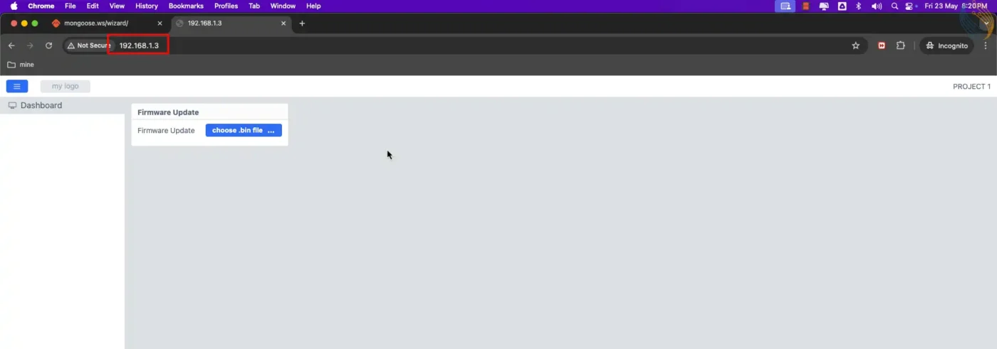
Below is the image showing the UI for the Project 1.
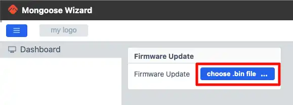
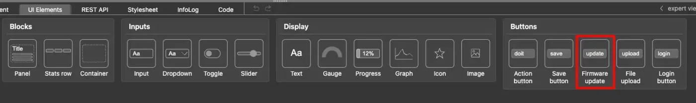
There is only a single panel containing a button to choose the .bin file. This is the Firmware Update button added from the UI elements as shown below.
The REST API for this button is automatically created. Below is the image showing the API for the firmware_update Button.
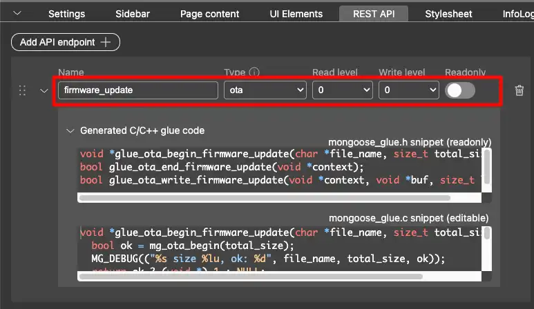
The API name is firmware_update and the type is ota. The functions generated by the mongoose wizard will be used to update the firmware on the device, so we do not need to modify anything from our end.
There is nothing more to modify on the wizard, so we will generate the project.
CubeIDE Configuration
We don’t need to modify anything in the cubeIDE as well. The IDE does not generate the binary file by default, so we will enable it in the properties.
Go to Project Properties -> C/C++ Build -> Settings -> Post Build Outputs and enable the binary file generation as shown in the image below.
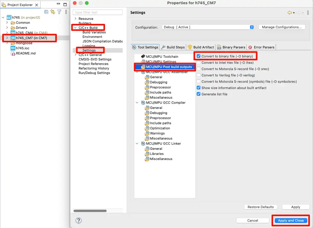
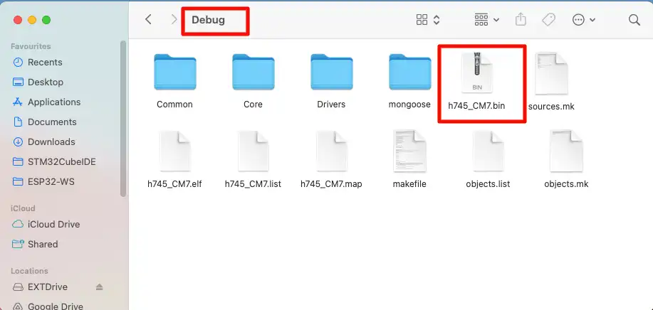
Once the project is build, the binary file will generate in the project -> Debug folder. We can flash this binary file from the webUI.
Run the Project
Flash this project to the board and check the logs on the serial console. Below is the image showing the logs on the serial terminal.
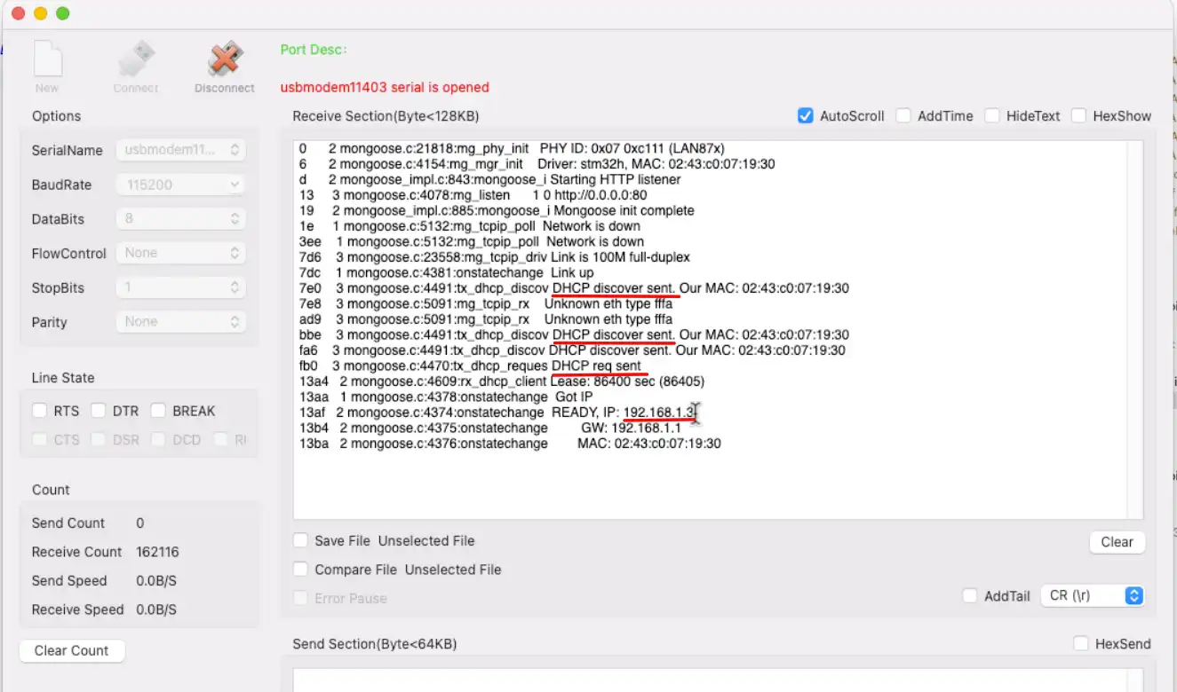
You can see in the image above, the DHCP sent the request for the IP. Afterwards it got the IP 192.168.1.3. We can now open this IP address in our browser. Below is the image showing the webUI responding to the IP address.
PROJECT 2
Project 2 will contain more elements in the UI to control the LEDs on the dev board. We also need to configure the pins in the cubeMX. This is to demonstrate that we can even modify the project as per our requirement and still use the mongoose OTA update.
Create the Web UI
I have already explained how to create the WebUI In the previous tutorial, So I will skip explaining every detail here. Let’s just focus on the elements and their APIs.
Below is the image showing the UI for the Project 2.
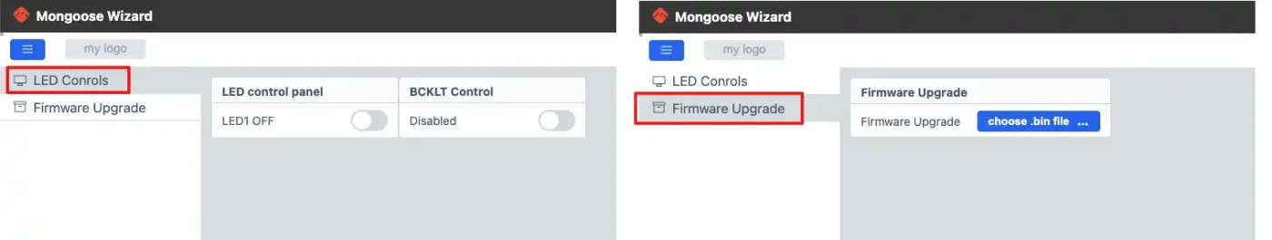
The UI contains 2 pages. The Page 1 has the toggle buttons to control the LEDs on the dev board. Page 2 contains the element to update the firmware Over The Air.
Page 1
Below is the image showing the details about the LED Control Panel on Page 1.
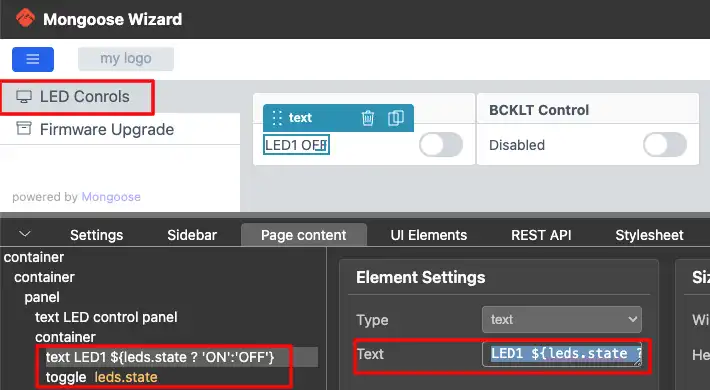
The text filed contains a fixed text (LED1) and the variable text. The variable text part will fetch the value of the state variable from the API (leds.state). If this value is a 1 (true), we will set the text ON, otherwise set the text OFF, ${leds.state ? ‘ON’:’OFF’}.
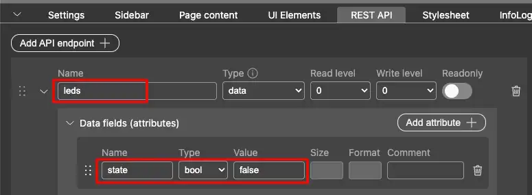
The REST API for the LED Toggle button is shown in the image below.
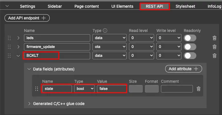
Below is the image showing the details about the BackLight Control Panel on Page 1.
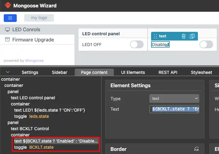
The text filed contains the variable text. We will fetch the value of the state variable from the API (BCKLT.state). If this value is a 1 (true), we will set the text Enabled, otherwise set the text Disabled, ${BCKLT.state ? ‘Enabled’ : ‘Disabled’}.
The REST API for the BCKLT Toggle button is shown in the image below.
Page 2
Page 2 only contains the element to update the Firmware. It consists of the text (Firmware Update) and the OTA button. Below is the image showing the Element on Page 2.
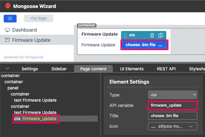
The API variable (firmware_update) for the ota button is assigned automatically. We do not need to modify anything here.
CubeMX Configuration
We need to configure the pins for the LED and the Display Backlight. We will do this in the cubeMX.
Below is the image showing the configuration for the LED pin PJ2.
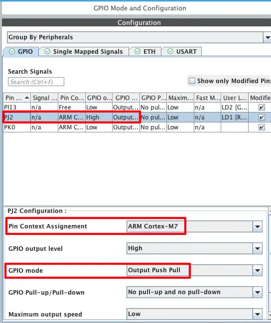
The Pin PJ2 is configured in the output mode. Since I am using a dual core dev board, I need to assign the pin to cortex M7 core.
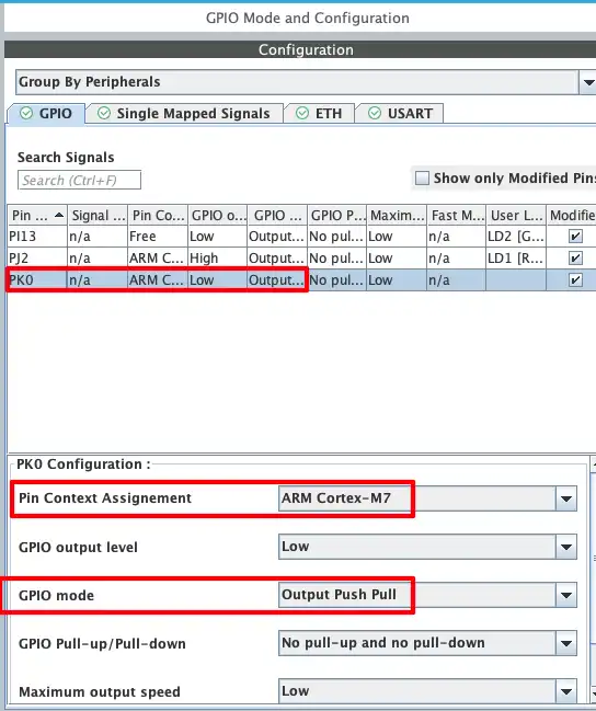
The Display Backlight is connected to the pin PK0. We also need to configure this pin in the output mode. Below is the image showing the configuration for the pin PK0.
The Code
The LED and Backlight control functions are pre-generated in the mongoose_glue.c file. This file regenerates each time the mongoose dashboard is updated. Hence it is always better to write getter and setter functions in some other file (like main.c).
LED Control Functions
Below are the getter and setter functions for the LED control.
void my_get_leds(struct leds *data) {
  if (HAL_GPIO_ReadPin(GPIOJ, GPIO_PIN_2)) data->state = 0;  // LED is OFF
  else data->state = 1;  // LED is ON
}
void my_set_leds(struct leds *data) {
  if (data->state) HAL_GPIO_WritePin(GPIOJ, GPIO_PIN_2, GPIO_PIN_RESET);  // turn LED ON
  else HAL_GPIO_WritePin(GPIOJ, GPIO_PIN_2, GPIO_PIN_SET);  // turn LED OFF
}The function my_get_leds will be called by the UI whenever it wants to fetch the status of the LED Pin. Here we will first read the pin PJ2. If the pin is set, that means the LED must be OFF, so we will assign the value 0 to the state variable of the API. Otherwise the LED must be ON, so we will assign the value 1 to the variable.
The function my_set_leds will be called by the UI whenever the toggle button is modified. Here we will read the state variable of the API. If this variable has the value 1, means that the toggle button is set to true, we will turn the LED ON by Resetting the pin PJ2. Otherwise the toggle button is set to false, so we will turn the LED OFF by Setting the pin PJ2.
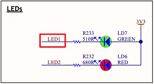
Note that Setting and Resetting the pin has an alternate behaviour with turning the LED OFF or ON. This is due to the connection of the LED on the dev board. The LED is connected between 3.3V and the pin PJ2. Hence when the pin is Reset, the LED turns ON and when the pin is Set, the LED turns OFF. This is shown in the image below.
BackLight Control Functions
Similarly, the getter and setter functions for the Backlight Control are shown below.
void my_get_BCKLT(struct BCKLT *data) {
  data->state = HAL_GPIO_ReadPin(GPIOK, GPIO_PIN_0);
}
void my_set_BCKLT(struct BCKLT *data) {
  HAL_GPIO_WritePin(GPIOK, GPIO_PIN_0, data->state);
}The LCD Backlight is connected to pin PK0. Hence here we will take a direct approach to control the backlight. The backlight turns OFF by resetting the pin PK0 and it turns ON by setting the pin. Therefore we can directly pass the value of the API Variable (data->state) to the HAL functions.
Main Function
We have created getter and setter functions for the LED controls but by default, the mongoose will use the functions it generated in the mongoose_glue.c file. In order to enable the mongoose to use our custom functions, we need to set the HTTP handlers for the APIs.
  /* USER CODE BEGIN 2 */
  mongoose_init();
  mongoose_set_http_handlers("leds", my_get_leds, my_set_leds);  // add this
  mongoose_set_http_handlers("BCKLT", my_get_BCKLT, my_set_BCKLT);  // add this
  for (;;) {
    mongoose_poll();
  }
/* USER CODE END 2 */We can do this after the mongoose_init() function. The function mongoose_set_http_handlers will assign our custom getter (my_get_leds) and setter (my_set_leds) functions to the provided API Endpoint (leds).
CubeIDE Configuration
We don’t need to modify anything in the cubeIDE as well. The IDE does not generate the binary file by default, so we will enable it in the properties.
Go to Project Properties -> C/C++ Build -> Settings -> Post Build Outputs and enable the binary file generation as shown in the image below.
Once the project is build, the binary file will generate in the project -> Debug folder. We can flash this binary file from the webUI.
RESULT
We have flashed the project 1 to the dev board and the server is already running on it.
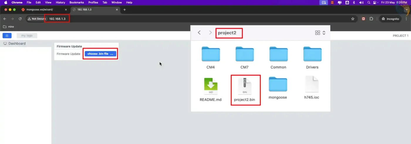
Click on the ota button and choose the project2.bin file. You can see the update logs in the serial console. Once the project is flashed, the board will reboot and the updated project will be loaded automatically.
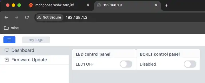
Below is the image showing the project 2 running on the dev board.
Below is the gif showing the LED controls working on the dev board.

STM32 Mongoose Ethernet Tutorial Series

STM32 Ethernet with Mongoose | Part 2 Web Server
STM32 Ethernet with Mongoose | Part 3 Weather Station
PROJECT DOWNLOAD
Subscribe
Login
0 Comments
Newest
