

STM32 DAC Tutorial: CubeMX Configuration and HAL Code on STM32H7
This is the first tutorial in the STM32 DAC series. In this series, we will go deep into the DAC peripheral and understand how it works. We will also see how to generate different waveforms with it and how to produce custom voltages on the STM32 pins.
A DAC allows the microcontroller to generate an analog voltage from a digital value. If we write a number to the DAC, it gives us a voltage on the output pin that matches that number. A higher number gives a higher voltage, and a lower number gives a lower voltage.
This first tutorial only covers the basics. We will configure the DAC using STM32CubeMX, write our first DAC program using the HAL library, and measure the output voltage with a multimeter. The deeper topics, such as the voltage calculation, the resolution, and the output control, will come in the next tutorials.
I have already covered the opposite peripheral in the STM32 ADC series, where an analog voltage is converted into a digital value. If you are new to analog peripherals, you can read the ADC single channel polling tutorial first, since the DAC follows a very similar workflow.
Table of contents
What Is a DAC in STM32
DAC stands for Digital to Analog Converter, and it converts a digital value into an equivalent analog voltage.
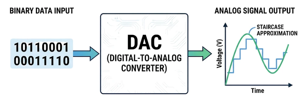
The microcontroller works with numbers, but many circuits in the real world work with voltages. The DAC acts as the bridge that lets the software control those circuits directly.
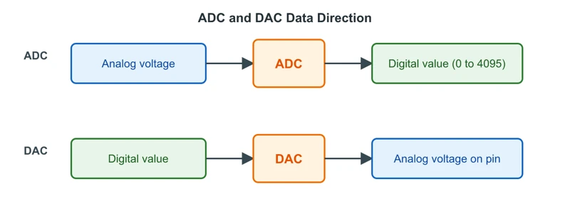
The ADC and the DAC are opposites of each other. The ADC samples a voltage and gives the software a number, while the DAC takes a number from the software and produces a voltage. The diagram below shows the direction of data in both cases.
Common Uses of a DAC
The most direct use of a DAC is to create a programmable analog voltage. For example, a reference voltage for another circuit can be changed by the software at any time, without replacing any hardware.
A DAC is also useful for simulating the output of a sensor. When we want to test our code without connecting the real sensor, we can write the values that the sensor would produce and let the DAC create the matching voltage. This is especially helpful in the early stages of a project, when the real sensor is not available yet.
The third common use is generating analog signals such as sine, triangle, and sawtooth waveforms. These signals can be used for audio or for testing other circuits. If you only need a simple analog level and not a precise one, you can also use a filtered PWM output, but a DAC gives a true voltage without any filtering circuit.
STM32H755ZI Nucleo Board
I am going to use the STM32H755ZI Nucleo board for this series. The DAC peripheral on these H7 boards is more advanced than the one on generic F4 or F1 series devices, so we can explore more of its features here. The same logic, with limited functionality, also works on other STM32 boards.
I have tested the basic DAC setup on the F4 series, on some G series boards, and on the L series. In all of them, the DAC was 12 bits wide with an optional 8-bit mode, so the code in this tutorial can be adapted to those boards without much change.
The H755 is a dual-core device with a Cortex-M7 and a Cortex-M4. We will only use the Cortex-M7 core throughout this series. If you want to understand how the two cores boot and synchronize, check out the video STM32 Dual Core MCUs Explained.
STM32 DAC CubeMX Configuration
Clock Configuration
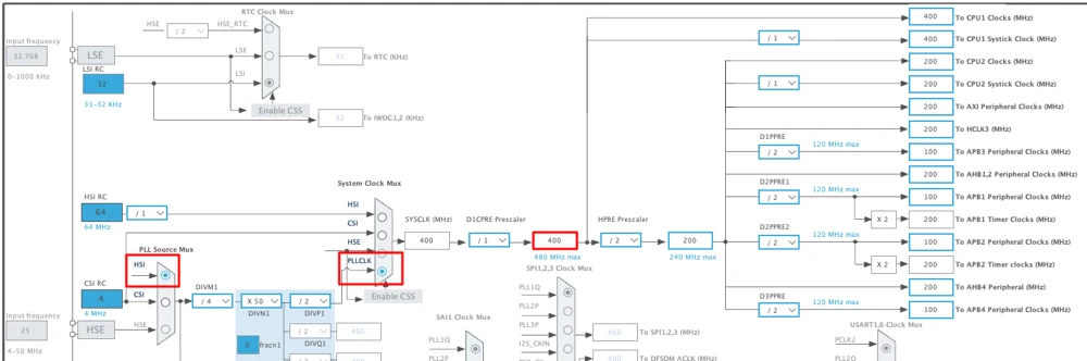
We will start with the clock configuration. I am using the internal clock of the Nucleo board and configuring it to generate a system clock of 400 MHz.
DAC Channels and Pin Routing
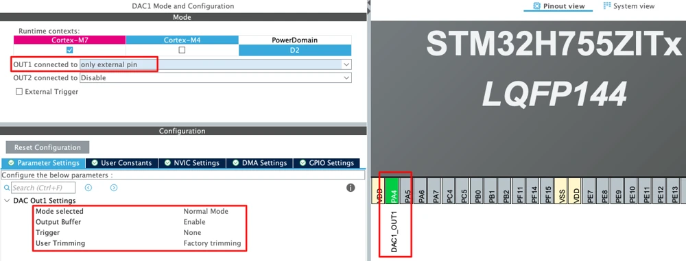
Under the Analog section, you will find one DAC peripheral. Enable it for the Cortex-M7 core, since this is the core we are using in this series.
This peripheral has two channels. OUT1 is the configuration for channel 1, and OUT2 is the configuration for channel 2. Under each of them, there are three connection options that decide where the DAC output goes.
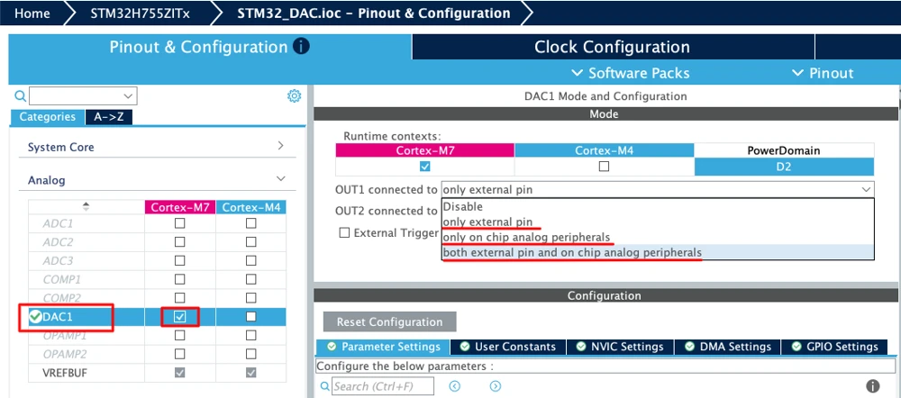
The first option connects the DAC output to the external pin only, so the signal is routed to a physical pin on the board. The second option connects the output to on-chip peripherals only, which means the DAC feeds the input of another peripheral inside the chip, such as the ADC, an op-amp, or a comparator. The third option allows both, so the output is available on the external pin and also inside the chip.
To keep things simple in this introductory tutorial, I am selecting the external pin only. Once this option is selected, CubeMX configures the pin PA4 as DAC1 OUT1. This is the channel 1 output, and it is the pin where we will measure the voltage with a multimeter.
DAC Parameter Settings
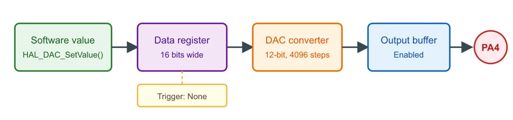
After selecting the pin routing, we can look at the parameters. The diagram below shows the path that the digital value takes inside the DAC, which will help in understanding the settings that follow.
Mode
The first option is the mode, where we can choose between Normal mode and Sample and Hold mode. In Sample and Hold mode, the DAC can keep its output voltage for some time without being refreshed continuously, which helps to save power. We will cover this mode later in the series, so for now I am keeping it in Normal mode.
Output Buffer
The second option is the output buffer, which is enabled by default, and we will leave it enabled. The output buffer reduces the output impedance of the DAC. In simple words, it allows the DAC to drive a connected load directly, without needing an external op-amp. If the buffer is disabled, the output has a high impedance, and the voltage can drop when a load is connected to it.
Trigger Selection
The trigger selection is set to None by default, and we will leave it as it is. A trigger is an event, such as a timer, that tells the DAC when to update its output. When the trigger is set to None, the DAC output is updated as soon as we write a new value from the software (code). The timer-based trigger options will be explored in the upcoming tutorials of this series, and you can refresh the timer basics from the STM32 timer tutorials in the meantime.
User Trimming
Finally, we have the User Trimming section. Here we keep the factory trimming, which means the DAC uses the calibration values that ST has stored at the factory. This option should be left as it is.
All the default options are selected in this tutorial, and we are keeping them that way.
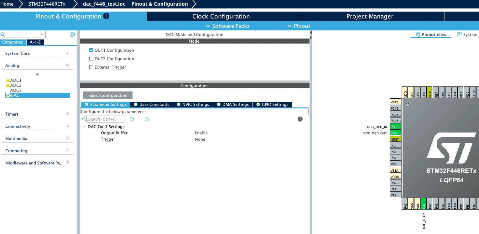
DAC Settings on the STM32F446
To give you an idea of how this looks on other boards, the DAC configuration on the STM32F446 is much simpler. There we only need to enable the output channel, and under the parameter settings we only have the output buffer and the trigger options, which can stay in their default states.
DAC Initialization Code
If you scroll down inside the main function, you will see that CubeMX has generated the MX_DAC1_Init() function. This function initializes the DAC peripheral first, and then it configures the channel according to the setup that we made in CubeMX. However, the initialization function does not start the DAC, so we need to start it manually.
After all the initialization functions are called in main, we call HAL_DAC_Start(). The first parameter is the DAC handle, and the second parameter is the channel that we want to start. Since I am using channel 1 in this tutorial, we pass DAC_CHANNEL_1.
/* USER CODE BEGIN 2 */
HAL_DAC_Start(&hdac1, DAC_CHANNEL_1);
/* USER CODE END 2 */Starting the DAC alone does not give us an analog voltage. We also have to provide the digital value that should be converted into the equivalent voltage. The function HAL_DAC_SetValue() is used for this purpose. This function takes four parameters: the DAC handle, the DAC channel, the alignment, and the data.
DAC handle and DAC channel will remain the same as we used in the HAL_DAC_Start() function, but we need to understand the rest of the two parameters. They are explained in the sections below.
DAC Data Alignment
The STM32 DAC is 12 bits in size, but it can also be configured in 8-bit mode. This is true for the all the STM32 microcontrollers. The problem is that the DAC data is 12 bits wide, while the data register that holds it is 16 bits wide. To fit the 12-bit value into the 16-bit register, the bits have to be placed either at the lower end or at the upper end of the register. This is exactly what right alignment and left alignment mean.
In the 12-bit right-aligned mode, the data is stored from bit 0 up to bit 11. In the 12-bit left-aligned mode, the data is stored from bit 4 up to bit 15. The diagram below shows both layouts.
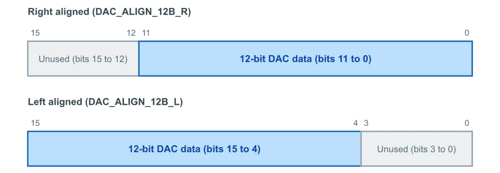
Right alignment is the simpler choice, because calculations are easier when the data starts from bit 0. A value of 100 in the application is also stored as 100 in the register, so there is no shifting involved. For this reason, I am going to use DAC_ALIGN_12B_R in the alignment parameter, which means 12-bit right aligned.
Set DAC Value with HAL_DAC_SetValue
Now we can call the HAL_DAC_SetValue() function. This function takes four parameters: the DAC handle, the DAC channel, the alignment, and the data. The data is the digital value for which we want to generate the analog voltage.
A 12-bit value ranges from 0 up to 4095. For the first test, I am passing 2048, which is half of the total number of steps, so we can see what voltage the DAC produces for this value.
/* USER CODE BEGIN 2 */
HAL_DAC_Start(&hdac1, DAC_CHANNEL_1);
HAL_DAC_SetValue(&hdac1, DAC_CHANNEL_1, DAC_ALIGN_12B_R, 2048);
/* USER CODE END 2 */Both functions are called only once, before the infinite loop. The DAC holds the last value that was written to it, so the voltage stays on the pin until we write a new value.
Testing the DAC Output Voltage
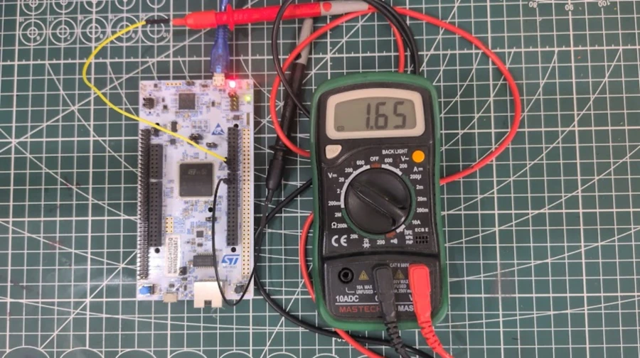
To test the output, connect the positive probe of the multimeter to PA4 and the negative probe to the ground pin of the board. Then flash the project and read the voltage.
With the value 2048, the multimeter shows around 1.64 to 1.65 volts. This is half of VDD, because the STM32 VDD is 3.3 volts. It is half because we gave the DAC a value that is exactly half of the total range, which has 4096 steps.
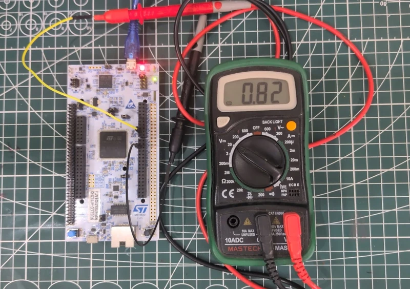
Next, I changed the value to 1024, which is one fourth of 4096. The multimeter now shows around 0.82 volts, and this is also one fourth of VDD. This confirms that the output voltage changes in proportion to the value that we supply.
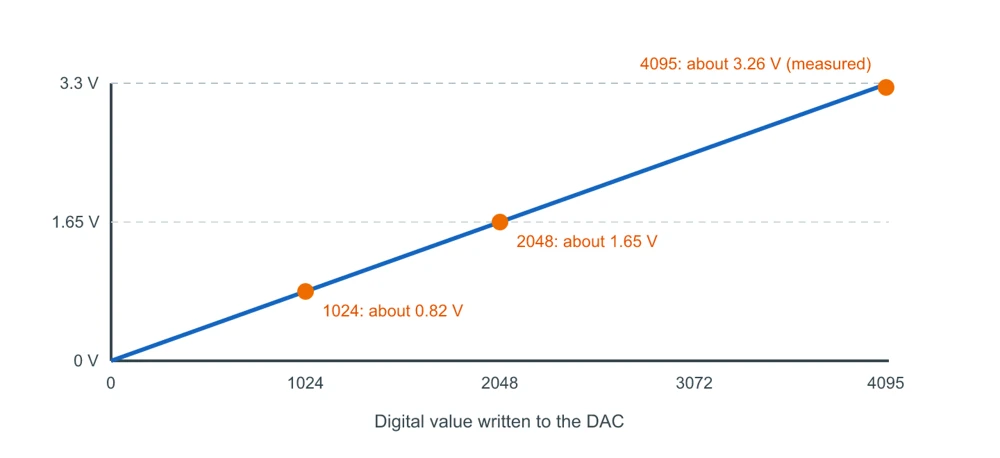
The table below summarizes the three tests. The expected values are calculated by multiplying the fraction of 4096 with the 3.3 volt supply.
| Value written | Fraction of 4096 | Expected voltage | Measured voltage |
|---|---|---|---|
| 1024 | 1/4 | 0.825 V | about 0.82 V |
| 2048 | 1/2 | 1.65 V | about 1.64 to 1.65 V |
| 4095 | almost 1 | about 3.30 V | about 3.26 to 3.27 V |
The graph below shows the same relationship. The output voltage rises in a straight line as the digital value increases, which is why we say that the output is directly proportional to the value written to the DAC.
The detailed calculation of the output voltage, the role of the reference voltage, and the way to use a custom reference are covered in the next tutorial of this series. If you want to understand how the reference voltage is handled on the analog side of the STM32, you can read the ADC reference voltage tutorial, since the DAC uses the same reference concept.
Conclusion
In this tutorial, we learned what a DAC is, where it can be used, and how to configure it in STM32CubeMX for the STM32H755ZI Nucleo board. We selected the external pin for channel 1, which put the output on PA4, and we kept the default values for the mode, the output buffer, the trigger, and the user trimming.
In the code, we started the DAC with HAL_DAC_Start() and wrote the digital value with HAL_DAC_SetValue() using the 12-bit right-aligned format. We also looked at why the alignment is needed, since the 12-bit data has to fit inside a 16-bit register. The multimeter readings confirmed that the output voltage is directly proportional to the value that we write, with 2048 giving about half of VDD, 1024 giving about one fourth, and 4095 giving a voltage very close to the supply.
In the next tutorial, we will look at the DAC voltage calculation, the resolution, and the output control in more detail. After that, we will use the timer trigger and DMA to generate waveforms, so make sure that you keep this project, since we will continue to modify it in every tutorial of the series.
Download Project Here
Download the CubeMX project files and HAL source code — all tested on real hardware.
If you find this useful, you can support us with a Donation as well.
Browse More STM32 DAC Tutorials
Coming Soon!