Published: November 16, 2024
Last Updated: March 23, 2026
Last Updated: March 23, 2026
STM32 ADC Single Channel with Interrupt and DMA
This is Part 2 of the STM32 ADC tutorial series, where we will read a single channel using Interrupt and DMA. In Part 1, we covered polling mode. Unlike polling, Interrupt and DMA let the CPU perform other tasks while the ADC runs conversions in the background. We will configure the ADC in CubeMX, write the code, and compare both methods with practical results.
This is the 2nd tutorial in the STM32 ADC series. I am going to use the STM32H750 based development board for this series because it has advanced ADC features. But I will also cover the configuration changes required for some of the popular series that includes STM32F103C8 and STM32F446RE.
This tutorial is a continuation of the previous one, so the configuration remains the same. This is the continuation of PART1, so you must go read PART1 first.
STM32 ADC Wiring Diagram
The image below shows the connection between STM32H750 and the Potentiometer.
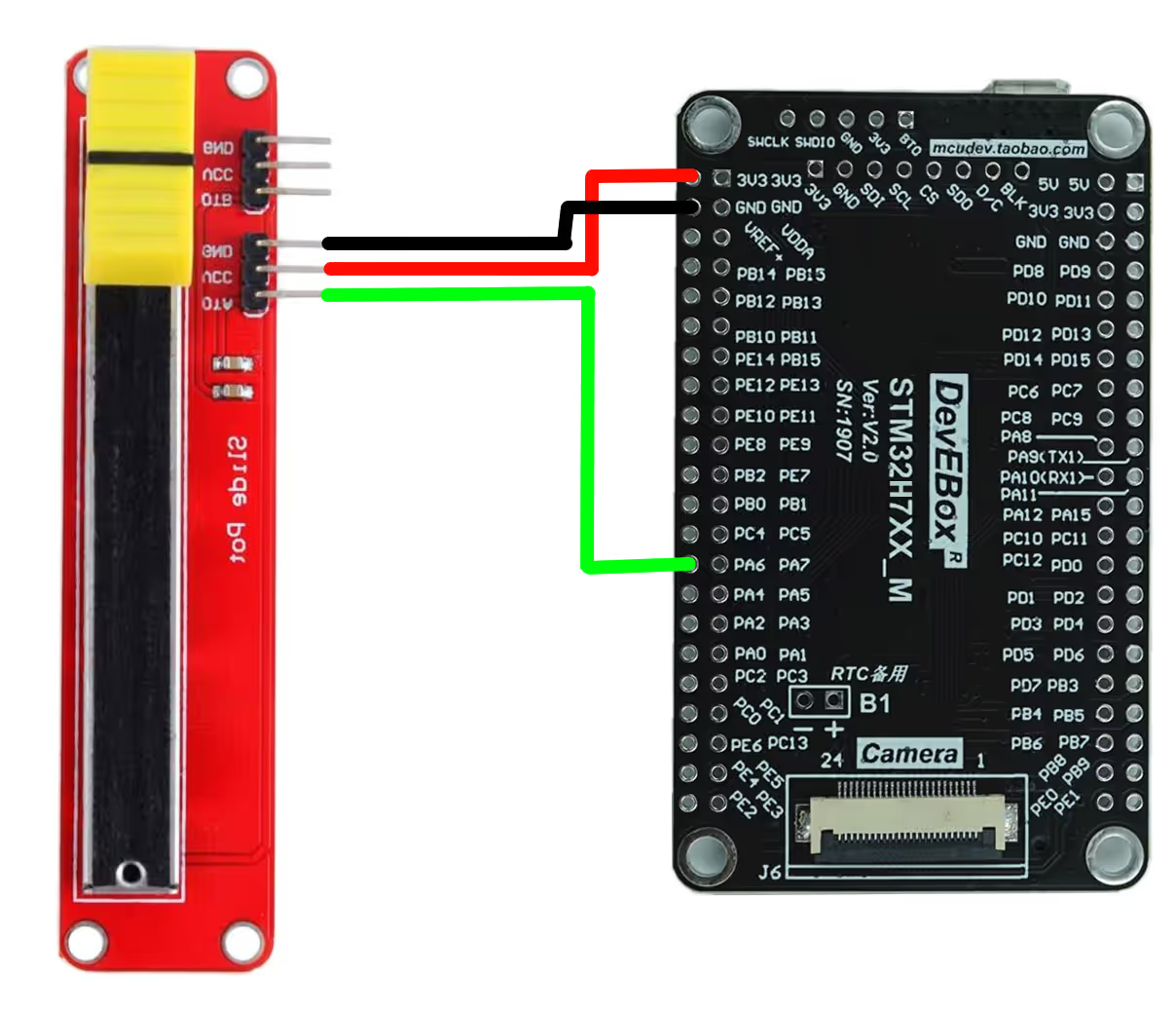
The pin connection is described in the table below.
| Potentiometer Pin | Connected To |
|---|---|
| VCC | 3.3V on STM32 |
| GND | GND on STM32 |
| OUT | PA6 (ADC1_INP3) Pin |
What Are ADC Interrupt Mode and DMA Mode in STM32
ADC Interrupt Mode in STM32
In interrupt mode, the ADC triggers an interrupt when a conversion is complete. The CPU is notified only when data is ready, so it does not need to check the status continuously. This makes the process more efficient than polling.
ADC DMA Mode in STM32
In DMA mode, the ADC sends the converted data directly to memory without CPU involvement. This allows continuous data transfer with minimal overhead. The CPU can handle other tasks while DMA manages data movement in the background.
When to Use Interrupt vs DMA
Use interrupt mode when conversions are occasional and CPU load is light. Use DMA mode when handling continuous conversions or large amounts of data for higher efficiency.
Comparison of ADC Interrupt Mode and DMA Mode in STM32
| Feature | Interrupt Mode | DMA Mode |
|---|---|---|
| CPU Involvement | CPU handles each conversion via ISR | CPU is free; DMA transfers data directly |
| Efficiency | Moderate – good for fewer conversions | High – best for continuous conversions |
| Complexity | Easier to implement | More complex to configure |
| Latency | Slight delay due to interrupt handling | Very low, as transfers are hardware-based |
| Best Use Case | Occasional or low-frequency sampling | High-speed or large-volume data transfers |
Interrupt mode works well when you only need occasional ADC readings without putting too much load on the CPU. On the other hand, DMA mode is the better choice for continuous or high-speed sampling, since it transfers data directly to memory with almost no CPU overhead.
ADC Interrupt Mode in STM32
In interrupt mode, the ADC notifies the CPU only when a conversion is complete. This removes the need for constant polling and lets the CPU focus on other tasks until the interrupt is triggered. It is a good choice when sampling is occasional or when you want to save processing time compared to polling.
CubeMX Configuration for Interrupt Mode
The image below shows the cubeMX configuration for the Single channel Interrupt Mode.
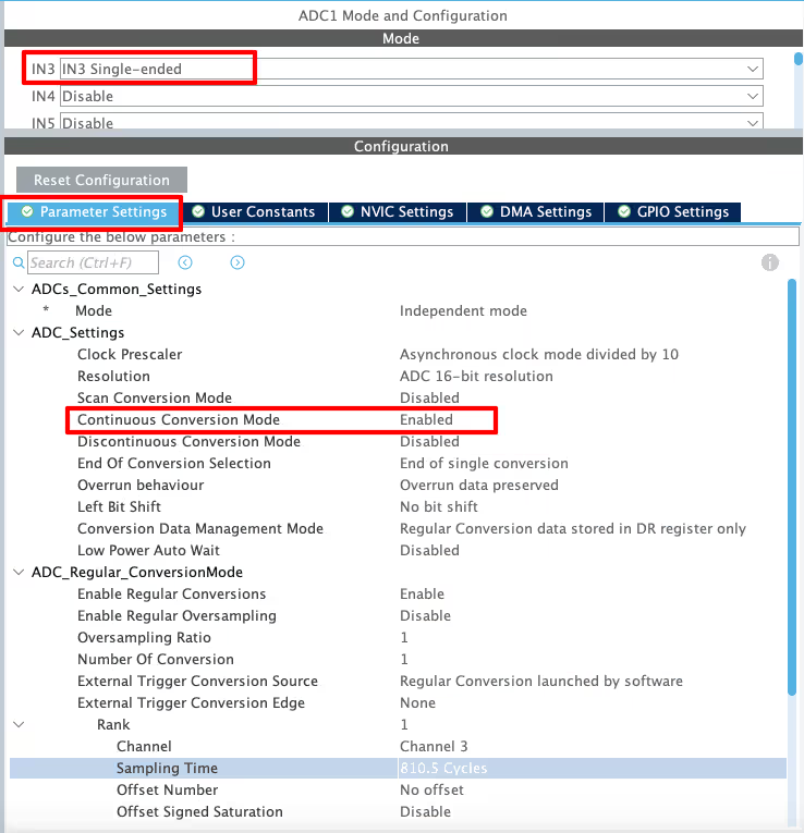
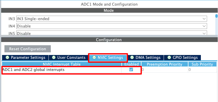
In the first image above, you can see that we need to enable Continuous Conversion Mode. This ensures that each new conversion starts right after the previous one finishes, so the process keeps running without interruption. In our case of a single channel, this setting makes sure the same channel is converted continuously, and the interrupt is triggered at a steady rate.
Next, go to the NVIC tab and enable the ADC Global Interrupt.
STM32 Code for ADC Interrupt Mode
The code will remain the same for all the STM32 MCUs. If there are any changes, I will specify in this section itself.
Definitions
Let’s define some variables, which we will use in the main function later.
uint16_t ADC_VAL = 0;
int value = 0;

long map(long x, long in_min, long in_max, long out_min, long out_max)
{
  return (x - in_min) * (out_max - out_min + 1) / (in_max - in_min + 1) + out_min;
}We define ADC_VAL as a 16-bit variable, and we use it to store the converted ADC value. Even if we select 10-bit, 12-bit, or 14-bit resolution, we still declare ADC_VAL as a 16-bit variable.
We will use the map function to map the converted ADC value to our desired range. The mapped value will be stored in the value variable, which I have defined as an integer here.
The main function
Below is the main function.
int main ()
{
....
....
HAL_ADC_Start_IT(&hadc1);
while (1)
{
}
}Inside the main function, we will start the ADC in the interrupt mode. Once the ADC finishes the sampling and conversion of the data from the channel, an interrupt will trigger and the Conversion complete callback will be called. We will write the rest of the code inside this callback function.
ADC Conversion Complete Callback
void HAL_ADC_ConvCpltCallback(ADC_HandleTypeDef *hadc)
{
ADC_VAL = HAL_ADC_GetValue(&hadc1);
value = map(ADC_VAL, 1700, 65535, 0, 100);
}Inside the callback we will read the converted value using the function HAL_ADC_GetValue. This function returns the ADC value based on the resolution set during the configuration.
We now have the converted data stored in the ADC_VAL variable. We will use the map function to map the converted value to 0 to 100 range. Since I have set the ADC resolution to 16bits, the maximum value of the ADC_VAL variable will be 216-1 = 65535. Similarly, the maximum value for the 12bits resolution will be 212-1 = 4095 and the same for the 10bits resolution will be 210-1 = 1023.
I have set the minimum input value to the map function as 1700. This is because it is the value we were getting when the slider was at the extreme left. Similarly the maximum value to the input of the map function will be 65535, as this is the highest value for the 16 bit resolution.
Result of ADC in Interrupt Mode
The gif below shows the ADC values obtained by moving the potentiometer, in the STM32CubeIDE debugger.

As you can see in the image above, the ADC value is more responsive now. Also the value variable varies from 0 to 100 as we move the slider from left to right.
This means that the ADC is working pretty fine in the interrupt mode. One important thing you need to remember is not to set the ADC clock too high. If the conversion time is very low, the interrupts will trigger at an extremely high rate and this will make the while loop unusable.
Basically you have to tradeoff between the sampling rate and the while loop.
ADC DMA Mode in STM32
Using DMA for a single channel does not provide much benefit. The interrupt still triggers at the same rate as it does in interrupt mode, so there is no noticeable advantage. However, for completeness, we will also cover the DMA mode in this tutorial.
CubeMX Configuration for Interrupt Mode
We will see the available configuration for all three MCUs i.e F103C8, F446RE and H750VB.
STM32F446RE ADC DMA Configuration
The image below shows the ADC DMA configuration for STM32F446RE.
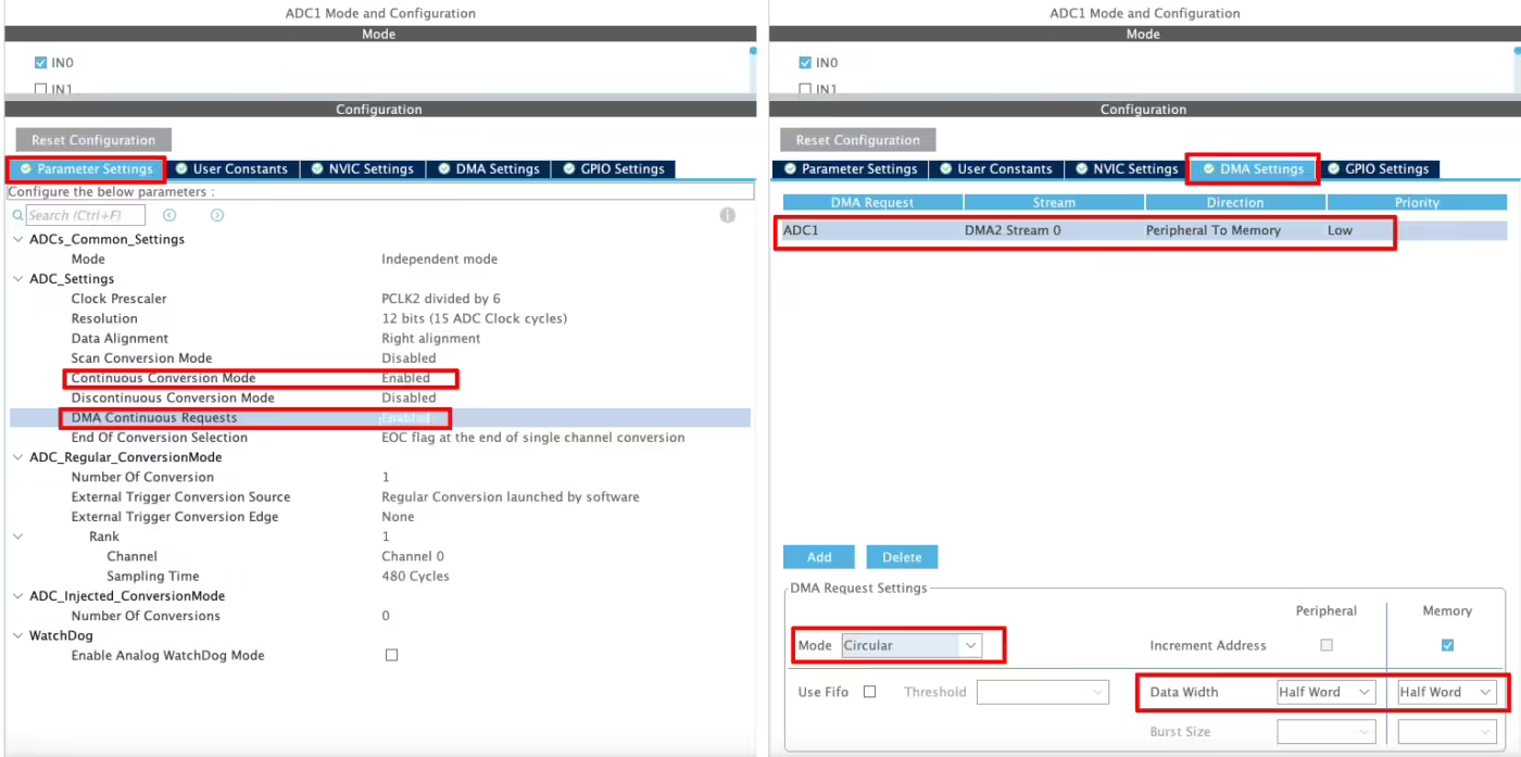
In the first image above, you can see that we need to enable Continuous Conversion Mode. This makes sure each new conversion starts right after the previous one, so the process runs continuously and the interrupt triggers at a steady rate. For a single channel, this ensures the same channel is converted without interruption.
On the F446RE, you will also find an option to enable DMA Continuous Request. With this enabled, the DMA can keep transferring data without needing to be restarted manually.
Next, go to the DMA settings and add a request for the ADC. Set the mode to Circular, so the DMA automatically re-triggers after each transfer. If you select Normal mode, the DMA stops after one transfer, and you must start it again.
Finally, if the ADC resolution is higher than 8 bits, set the Data Width to Half Word (16 bits).
STM32F103C8 ADC DMA Configuration
The image below shows the ADC DMA configuration for the STM32F103C8.
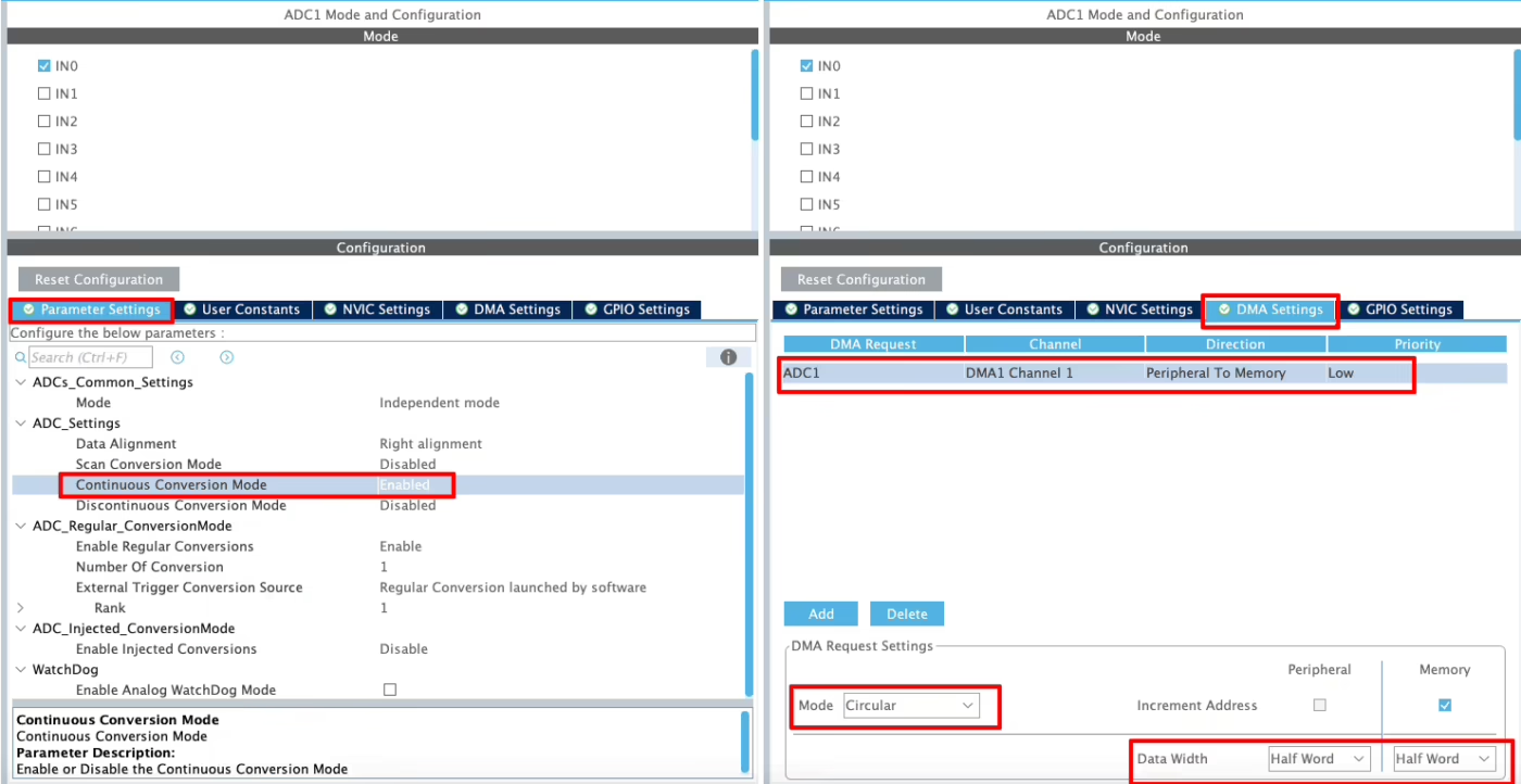
As shown in the image above, we need to enable Continuous Conversion Mode. This ensures that each new conversion starts right after the previous one finishes, so the process keeps running and the interrupt triggers at a steady rate. For a single channel, this makes sure the same channel is converted continuously.
Unlike the F446RE, the F103C8 does not provide an option to enable DMA Continuous Request. Since this feature is missing, we simply configure the DMA in Circular mode, which automatically allows DMA to request data transfers continuously.
In the DMA settings, add a request for the ADC and make sure the mode is set to Circular. This lets DMA re-trigger itself after each transfer. If you use Normal mode, the transfer will stop after one cycle, and you will need to restart it manually.
Finally, if the ADC resolution is higher than 8 bits, set the Data Width to Half Word (16 bits).
STM32H750 ADC DMA Configuration
The image below shows the ADC DMA configuration for the STM32H750VB.
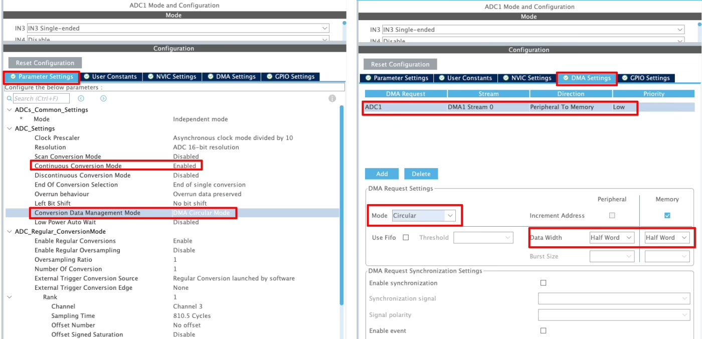
As shown in the image above, we need to enable Continuous Conversion Mode. This makes sure that each conversion starts right after the previous one finishes, so the process runs continuously and the interrupt triggers at a steady rate. For a single channel, this ensures that the same channel is converted without stopping.
Here we also have a new option called Conversion Data Management Mode. This setting lets us decide what to do with the converted data. We can either keep the result in the ADC Data Register (DR) or use DMA to transfer it automatically. In this tutorial, we will use DMA Circular Mode, which allows DMA to continuously move the converted data without manual intervention.
Next, open the DMA settings and add a request for the ADC. Be sure to set the DMA mode to Circular so that it can re-trigger automatically after each transfer. If you choose Normal mode, the transfer stops after one cycle, and you would need to restart it manually.
Finally, if the ADC resolution is higher than 8 bits, set the Data Width to Half Word (16 bits).
Code for ADC DMA Mode
The code will remain the same for all the STM32 MCUs. If there are any changes, I will specify in this section itself.
Definitions
Let’s define some variables, which we will use in the main function later.
uint16_t ADC_VAL = 0;
int value = 0;

long map(long x, long in_min, long in_max, long out_min, long out_max)
{
  return (x - in_min) * (out_max - out_min + 1) / (in_max - in_min + 1) + out_min;
}
We define ADC_VAL as a 16-bit variable, and we use it to store the converted ADC value. Even if we select 10-bit, 12-bit, or 14-bit resolution, we still declare ADC_VAL as a 16-bit variable.
We will use the map function to map the converted ADC value to our desired range. The mapped value will be stored in the value variable, which I have defined as an integer here.
The main function
Below is the main function.
int main ()
{
  ....
  ....
  HAL_ADC_Start_DMA(&hadc1, (uint32_t *)ADC_VAL, 1);
  while (1)
  {
  }
}Inside the main function, we will start the ADC in the DMA mode. The parameter ADC_VAL is the array where we want to store the converted data, and 1 is the number of conversions we want the DMA to transfer.
Once the DMA finishes the transfer of the converted data from the channel, an interrupt will trigger and the Conversion complete callback will be called. We will write the rest of the code inside this callback function.
ADC Conversion Complete Callback
void HAL_ADC_ConvCpltCallback(ADC_HandleTypeDef *hadc)
{
	  value = map(ADC_VAL[0], 1700, 65535, 0, 100);
}Unlike the interrupt mode, Inside the callback we do not need to use the function HAL_ADC_GetValue. The data is already stored in the ADC_VAL array, therefore we can simply process this data.
We now have the converted data stored in the ADC_VAL variable. We will use the map function to map the converted value to 0 to 100 range. Since I have set the ADC resolution to 16bits, the maximum value of the ADC_VAL variable will be 216-1 = 65535. Similarly, the maximum value for the 12bits resolution will be 212-1 = 4095 and the same for the 10bits resolution will be 210-1 = 1023.
I have set the minimum input value to the map function as 1700. This is because it is the value we were getting when the slider was at the extreme left. Similarly the maximum value to the input of the map function will be 65535, as this is the highest value for the 16 bit resolution.
Cortex-M7 Specific Configuration for ADC with DMA
In this section, we will look at the configuration and code required specifically for Cortex-M7 devices.
ST recommends enabling both the Instruction cache and Data cache to improve system performance. However, when these caches are active, DMA often runs into cache coherency issues. To handle this problem, we use the Memory Protection Unit (MPU) available on Cortex-M7, which ensures proper data consistency between cache and memory.
The image below shows an example of the MPU configuration for Cortex-M7 devices.
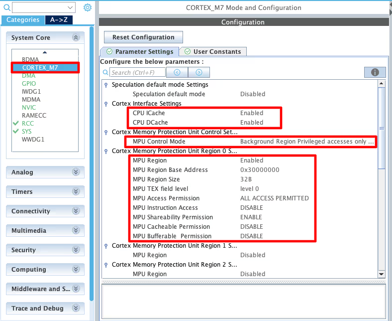
As you can see in the image above, I have enabled both Instruction and Data Cache (ICache & DCache).
We also need to enable the MPU in the MPU_PRIVILEGED_DEFAULT mode. Here I am choosing the Base Address region 0x30000000, this is the region for the RAM_D2 and we will relocate our buffer in this region.
- Here I have selected the 32 Bytes region, since it’s the least size available. The ADC Buffer is going to be 20 bytes in size.
- The rest of the configuration is to set the region as non-cacheable region. This would prevent the cache coherency issue between the CPU and the DMA.
Inside the main file, we need to relocate the ADC_VAL array to the RAM_D2 Region, 0x30000000. We can do this by using the section attribute as shown below. Here I am relocating the ADC_VAL array to the section “.adcarray“.
__attribute__((section(".adcarray"))) uint16_t ADC_VAL[10];The section (.adcarray) will be defined in the flash script file as shown below.
  .mysection (NOLOAD):
  {
    . = ABSOLUTE(0x30000000);
    *(.adcarray)
} >RAM_D2As you can see above, the section (.adcarray) is linked to the region RAM_D2 (0x30000000).
The rest of the code remains the same as we used in the DMA section.
Result of ADC in DMA Mode
The gif below shows the ADC values obtained by moving the potentiometer, in the STM32CubeIDE debugger.

As you can see in the gif above, the first element of the ADC_VAL array is updating continuously. The value variable also varies with the slider.
This means that the DMA is continuously transferring the data, and it is working fine even with the cache being enabled. There is no issue of the cache coherency, otherwise the data in the ADC_VAL array would not update at all.
Video Tutorial
STM32 ADC Interrupt & DMA Video Tutorial
This guide explains how to configure and code STM32 ADC in Interrupt and DMA modes using CubeMX. You’ll see how to set up continuous conversions, handle data with interrupts, and manage transfers with DMA circular mode. To make the process easier, I’ve also created a step-by-step video walkthrough showing the configuration, coding, and results. Follow the written tutorial here while watching the video for a clearer understanding.
Watch the VideoConclusion
In this tutorial, we learned how to use the STM32 ADC in single-channel Interrupt mode and DMA mode. Unlike polling mode, both approaches allow the ADC to operate in the background while the CPU continues executing other tasks. Interrupt mode is well suited for infrequent or event-based ADC conversions, whereas DMA mode is ideal for continuous sampling and high-speed data acquisition with minimal CPU involvement.
This tutorial is Part 2 of the STM32 ADC tutorial series. In the upcoming parts, we will move on to multi-channel ADC configurations and explore more advanced and practical use cases commonly found in real-world applications.
Next Tutorials in the STM32 ADC Series
STM32 ADC Part 3 – Multiple Channels with DMA Normal Mode
STM32 ADC Part 4 – Multiple Channels with DMA Circular Mode
STM32 ADC Part 5 – Read Multiple‑Channel without DMA
STM32 ADC Part 6 – ADC Conversion Time Explained
STM32 ADC PART 7 – ADC External Trigger Source Selection
STM32 ADC Part 8 – Injected Conversion Mode

I needed to add HAL_ADC_Start_IT(&hadc1) again in ADC Callback function to continuously get data, otherwise ADC is stopping after 1 conversion even though I have enabled continuous conversion in STM32F401RE. Same case with DMA I have to start ADC by HAL_ADC_Start_DMA in callback function