
Home ▸ STM32 Tutorials ▸ STM32 I2C ▸
Published: August 2, 2025
Last Updated: February 6, 2026
Last Updated: February 6, 2026
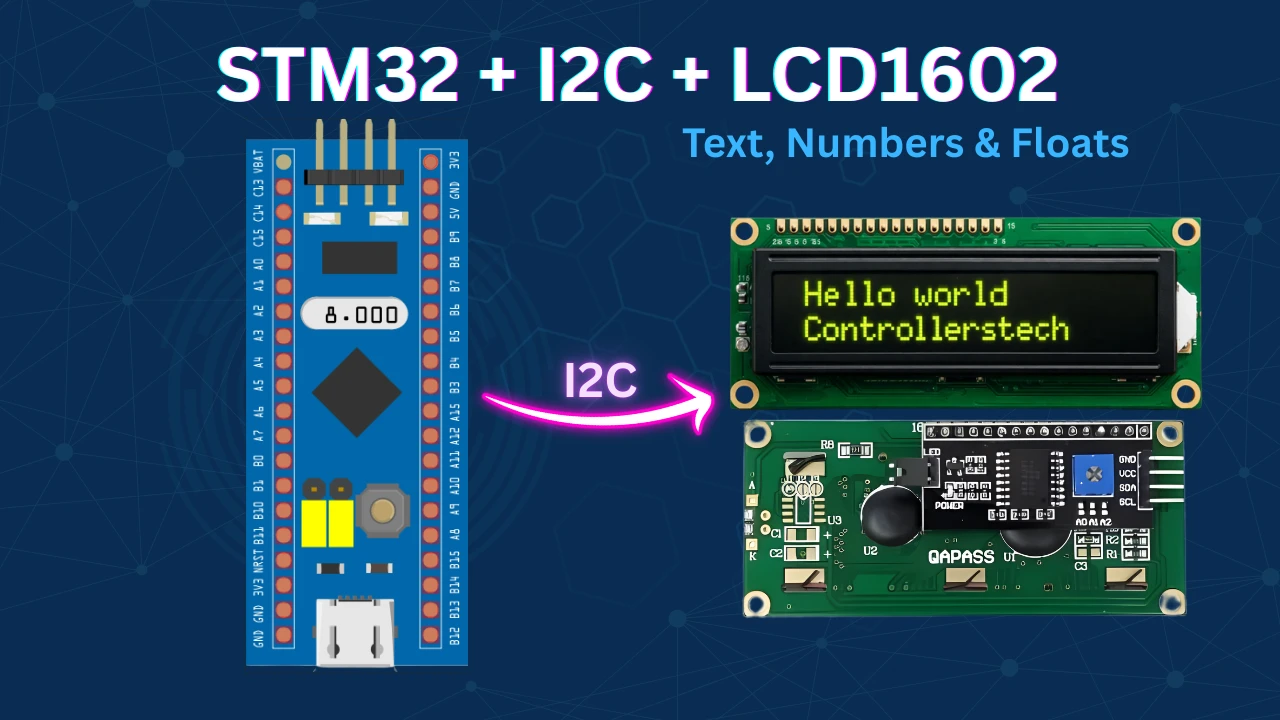
Interface LCD16x2 with STM32 using I2C
The STM32 I2C LCD1602 display is a simple yet powerful way to show text in embedded applications. In this guide, you’ll learn how to connect an I2C LCD with STM32 using the PCF8574 I/O expander and HAL library. By using only SDA and SCL lines, you can reduce GPIO usage and quickly display characters, numbers, and strings on a 16×2 LCD. This tutorial includes working code for lcd_init, lcd_send_cmd, and lcd_send_data, and works perfectly with STM32CubeIDE.
In this tutorial, you’ll learn how to connect and control a 16×2 I2C LCD (LCD1602) with an STM32 microcontroller using the PCF8574 I/O expander. We’ll walk through the wiring setup, explain how the I2C communication works with the LCD, and implement essential HAL functions to initialize the display, send commands, and print characters or strings. The tutorial also provides a clean and reusable code structure compatible with STM32CubeIDE, making it easy to integrate into your own projects.
You can also check out some other Displays interfaced with STM32 Microcontrollers:
- Interface LCD 20×4 with STM32 using the I2C.
- Interface LCD1602 display with built‑in I²C driver AIP31068.
- Interface SSD1306 OLED Display with STM32 (via I²C).
- Interface SH1106 1.3″ OLED with STM32 via I²C.
- Interface LCD 16×2 with STM32 without I²C.
- Interface 2.8″ ILI9341 Display with STm32 using SPI.
STM32 LCD1602 I2C Project Requirement
I’ve used products mentioned below in this project. I have also added affiliate links for your convenience — if you purchase through these links, it helps support my work at no extra cost to you.
- STM32 development board
- 16×2 I2C LCD module
- Jumper wires and
- Breadboard
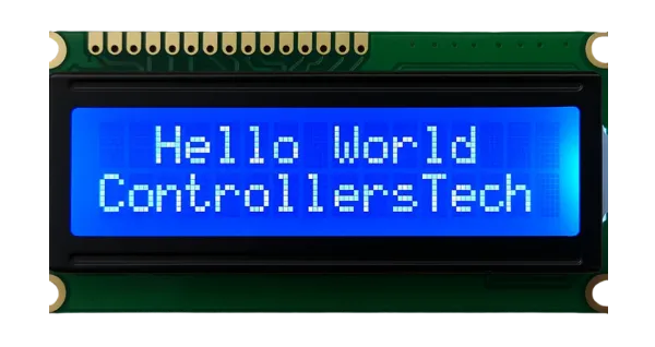
What is LCD1602 I2C Display and How It Works with STM32
The LCD1602 is a widely used 16×2 alphanumeric display module capable of showing 2 lines of 16 characters each. The standard module requires at least 6 GPIO pins to interface with a microcontroller, but adding the PCF8574 I/O expander simplifies this by enabling communication over the I²C bus using just two lines—SDA and SCL. This greatly reduces wiring complexity and conserves GPIO resources on the STM32 or any microcontroller. The PCF8574 handles parallel-to-serial data conversion, making the setup ideal for compact or resource-constrained embedded systems.
Some of its important features are:
- I²C Communication: Reduces pin count from 6+ to just 2 (SDA and SCL), freeing up valuable MCU GPIOs.
- Built-in Backlight and Contrast Control: Allows brightness adjustment and contrast tuning using onboard trimpots or software.
- Compact and Readable Display: Displays 16 characters × 2 lines, suitable for status messages, sensor values, and basic UI.
- Wide Compatibility: Works seamlessly with STM32, Arduino, ESP32, and other microcontrollers through I²C protocols.
Why should you use the LCD16x2 Display ?
The LCD16x2 display is a simple yet highly effective solution for showing text-based information in embedded systems. It’s ideal for projects that need basic human-readable output without the complexity or resource demands of graphical displays. Whether you’re displaying sensor data, system status, or debug messages, the LCD16x2 offers a reliable and cost-efficient option. Its wide availability, low power consumption, and straightforward interfacing make it a go-to choice for hobbyists and professionals alike.
Reasons to Use the LCD16x2 Display
- Easy to Interface – Works with 4-bit/8-bit parallel or I²C using PCF8574.
- Low Power Consumption – Suitable for battery-powered and low-power applications.
- Cost-Effective – Very affordable for displaying basic textual output.
- Readability – Sharp contrast and backlight make it easy to read even in low light.
- Widely Supported – Compatible with STM32, Arduino, ESP32, and many platforms.
- No Complex Libraries Needed – Simple functions like send command/data are enough to operate.
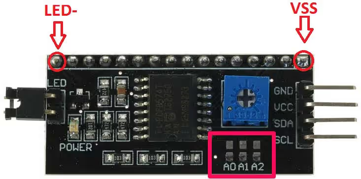
PCF8574 I2C Address Configuration Explained
The PCF8574 I/O Expander works with the I2C protocol, and every device on the I2C bus needs a unique address. The PCF8574 default address is fixed at the higher 4 bits (0100), while the lower 3 bits (A2, A1, A0) can be changed to avoid conflicts.
Why change the PCF8574 I2C address?
If you use only one PCF8574 chip, you don’t need to change its address. However, when you connect multiple devices—such as two or more I2C LCD1602 displays—you must assign different I2C addresses to each chip. Otherwise, address conflicts will occur, and the devices will not work properly on the same I2C bus.
PCF8574 Address Format
The address structure looks like this:
0100 A2 A1 A0 R/W
- A2, A1, A0 → Selectable address pins
- R/W → Defines Read (1) or Write (0) operation
Default PCF8574 Address
By default, all three pins (A0, A1, A2) are HIGH.
- Default binary address: 0100 1110
- Default hexadecimal address: 0x4E
How to change the PCF8574 address?
To set a new address:
- Connect any of the pins A0, A1, A2 to GND.
- Each change gives you a new valid I2C address.
Example:
- If A0 = GND, the new address becomes 0100 1100 (0x4C).
This way, you can connect up to 8 PCF8574 devices (or 8 LCDs) on the same I2C bus.
Important: The last bit (R/W) is not part of the actual device address. It only tells whether the operation is read or write.
STM32 LCD1602 I2C Schematic and Pinout (PCF8574 Module)
The image below shows the PCF8574 module which connects at the back of the LCD 16×2.
The first pin of the device is Vss which is pin 1 of LCD. So all you have to do is connect first pins of the LCD to Vss above and rest of them will connect accordingly. Starting with Vss as first pin, connection is as follows:-
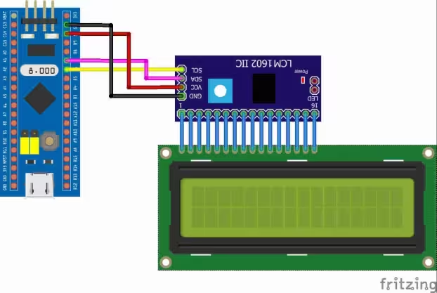
The 16 pins from the PCF8574 module are connected to the LCD16x2. The connection with the STM32 is shown in the table below.
| PCF8574 Pin | STM32F103 Pin | Description |
|---|---|---|
| VCC | 5V | Power supply (5V) |
| GND | GND | Ground |
| SDA | PB7 | I²C Data line |
| SCL | PB6 | I²C Clock line |
STM32CubeMX Configuration
In this section, we’ll set up STM32CubeMX for I2C communication, pin mapping, clock settings, and code generation to prepare the project.
STM32 Clock Configuration
Below is the image showing the clock configuration for the project.
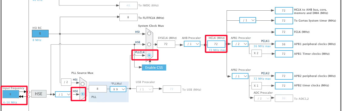
The STM32F103 is clocked by the external 8MHz crystal. We will use the PLL to run the system at maximum 72MHz clock.
LCD16x2 I2C Configuration
Below is the image showing the I2C configuraion.
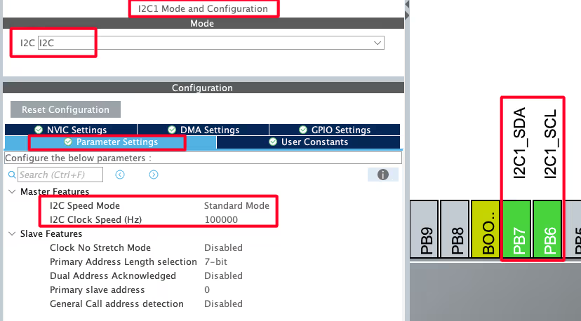
I am using the I2C1 to connect the LCD. The I2C is configured in the standard mode, with the clock speed set to 100KHz.
The pins PB6 and PB7 are configured as the SCL and SDA pins. These pins are connected to the respective pins of the PCF8574 as shown in the connection diagram.
STM32 I2C LCD1602 HAL Code Example
Let’s take a detailed look at the pinout of the PCF8574.
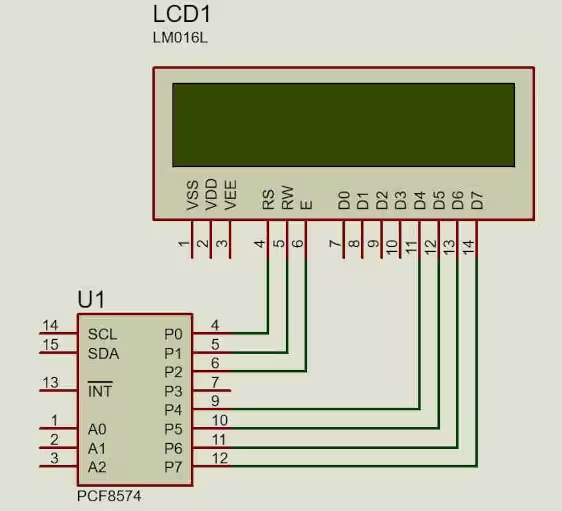
As you can see above,
- P0 is connected to the pin RS of the LCD. This RS pin is defines whether the transmitted byte is a command (0) or Data (1).
- P1 is connected to the R/W pin of the LCD. This pin should be LOW when writing the data to the LCD and HIGH when reading the data from the LCD.
- P2 is connected to the Enable pin of the LCD. This pin is used for the strobe (E=1 & E=0).
- P3 is connected to the Backlight of the Display. Setting this pin to 1 will turn the backlight ON.
- P4 – P7 are connected to the data pins D4 – D7. Since only 4 data pins are available in the PCF8574, we need to configure the LCD in the 4bit Mode.
PCF8574 Address Definition
#define SLAVE_ADDRESS_LCD 0x4E // change this according to ur setupThe default slave address defined in the i2c-lcd.c is 0x4E. This is default Address for the PCF8574, if the pins A0 A1 and A2 are not modified. It is already explained above in the Address section.
Sending LCD 16×2 Command
The function below actively sends a command byte to the LCD using the PCF8574 I2C expander in 4-bit mode.
void lcd_send_cmd (char cmd)
{
    char data_u, data_l;
    data_u = (cmd & 0xF0);           // extract upper 4 bits
    data_l = ((cmd << 4) & 0xF0);    // extract lower 4 bits

    uint8_t data_t[4];

    // send upper 4 bits with enable pulse
    data_t[0] = data_u | 0x0C;   // EN=1, RS=0  -> bxxxx1100
    data_t[1] = data_u | 0x08;   // EN=0, RS=0  -> bxxxx1000

    // send lower 4 bits with enable pulse
    data_t[2] = data_l | 0x0C;   // EN=1, RS=0  -> bxxxx1100
    data_t[3] = data_l | 0x08;   // EN=0, RS=0  -> bxxxx1000

    HAL_I2C_Master_Transmit(&hi2c1, SLAVE_ADDRESS_LCD, (uint8_t *) data_t, 4, 100);
}Step-by-Step Explanation
- This function accepts a command byte as its input parameter.
- Because the LCD runs in 4-bit mode, the function immediately splits the command into two parts:
- The upper 4 bits (
data_u) - The lower 4 bits (
data_l)
- The upper 4 bits (
- Then, the function processes each part separately before transmitting it via I2C communication.
PCF8574 Pin Mapping
As explained in the image above, the PCF8574 I/O expander controls the LCD through its 8 pins (P0–P7). Here is the mapping:
- P0 → RS (Register Select): set RS = 0 for command mode.
- P1 → R/W (Read/Write): always 0 because we only write.
- P2 → EN (Enable pin): toggled high and low to strobe data.
- P3 → Backlight control: set to 1 to keep the LCD backlight ON.
- P4–P7 → Data lines (D4–D7): carry the actual 4-bit data.
By controlling these pins, we actively manage how each command reaches the LCD.
How the Function Sends Data
To transmit data reliably, the function uses a strobe method:
- Send the upper 4 bits first
- Set EN = 1 → latch the data
- Set EN = 0 → complete the transfer
- This process follows the LCD datasheet requirement.
- Send the lower 4 bits next
- Again, toggle EN from 1 to 0 to ensure proper latching.
- Transmit all 4 bytes via I2C
- The function finally calls
HAL_I2C_Master_Transmitto send the 4 prepared bytes to the LCD using the STM32 I2C peripheral.
- The function finally calls
Why This Function Works
Because the LCD only accepts 4 bits at a time in 4-bit mode, this function ensures smooth data transfer. It actively splits the command, applies the correct PCF8574 pin configuration, and strobes the enable pin at the right moments. As a result, the LCD receives each command correctly and performs the desired operation.
Sending LCD16x2 Data
The data is sent in the similar manner as the command. The only difference is that the RS bit (P0) will be 1. This is to indicate that the transmitted byte is a data byte.
void lcd_send_data (char data)
{
	char data_u, data_l;
	uint8_t data_t[4];
	data_u = (data&0xf0);
	data_l = ((data<<4)&0xf0);
	data_t[0] = data_u|0x0D;  //en=1, rs=1 -> bxxxx1101
	data_t[1] = data_u|0x09;  //en=0, rs=1 -> bxxxx1001
	data_t[2] = data_l|0x0D;  //en=1, rs=1 -> bxxxx1101
	data_t[3] = data_l|0x09;  //en=0, rs=1 -> bxxxx1001
	HAL_I2C_Master_Transmit (&hi2c1, SLAVE_ADDRESS_LCD,(uint8_t *) data_t, 4, 100);
}Initialize I2C LCD16x2
Below is the function to initialise the LCD in the 4bit mode. The initialisation requires us to send a few set of command in a particular order. These commands and sequence are provided in the LCD1602 Datasheet. The code below is commented properly, so you can understand what is the function of each command.
void lcd_init (void)
{
  // 4 bit initialisation
  HAL_Delay(50);  // wait for >40ms
  lcd_send_cmd (0x30);
  HAL_Delay(5);  // wait for >4.1ms
  lcd_send_cmd (0x30);
  HAL_Delay(1);  // wait for >100us
  lcd_send_cmd (0x30);
  HAL_Delay(10);
  lcd_send_cmd (0x20);  // 4bit mode
  HAL_Delay(10);

  // display initialisation
  lcd_send_cmd (0x28); // Function set --> DL=0 (4 bit mode), N = 1 (2 line display) F = 0 (5x8 characters)
  HAL_Delay(1);
  lcd_send_cmd (0x08); //Display on/off control --> D=0,C=0, B=0  ---> display off
  HAL_Delay(1);
  lcd_send_cmd (0x01);  // clear display
  HAL_Delay(2);
  lcd_send_cmd (0x06); //Entry mode set --> I/D = 1 (increment cursor) & S = 0 (no shift)
  HAL_Delay(1);
  lcd_send_cmd (0x0C); //Display on/off control --> D = 1, C and B = 0. (Cursor and blink, last two bits)
}The above code is with reference to the pattern given for the initialization in the datasheet of the device.
Basically the function initializes the LCD in 4-bit mode.
- It starts with delays and
0x30commands to ensure the LCD resets properly, then switches to 4-bit mode with0x20. - Next, it configures the display with
0x28(4-bit, 2-line, 5×8 font). - It turns the display off (
0x08), clears it (0x01), sets entry mode (0x06, auto-increment cursor, no shift), and finally turns the display on without cursor/blink (0x0C).
Send String to I2C LCD16x2
We can send a single data byte using the function lcd_send_data(), but to send the entire string or a character array, we will write a separate function.
void lcd_send_string (char *str)
{
  while (*str) lcd_send_data (*str++);
}The function lcd_send_string() can be used to send an entire string to the display. The parameter of this function is the pointer to the string or array, that you want to send.
The loop while (*str) keeps running as long as the current character in the string is not the null terminator. In other words, it processes each character of the string one by one until the end.
Set Cursor Position on LCD16x2
The function lcd_put_cur() moves the cursor to a specific row and column of the LCD.
void lcd_put_cur(int row, int col)
{
    switch (row)
    {
        case 0:
            col |= 0x80;
            break;
        case 1:
            col |= 0xC0;
            break;
    }
    lcd_send_cmd (col);
}For a 16×2 LCD:
- Row 0 starts at DDRAM address
0x00→ Command = (0x80 | col) - Row 1 starts at DDRAM address
0x40→ Command = (0x80 | 0x40 | col) → (0xC0 | col)
For Example: lcd_put_cur(1,3) → cursor goes to row 1, column 3 (0xC3).
STM32 LCD16x2 HAL main() function
Now we will print some data on the LCD16x2 display using our functions inside the main function of the STM32 project.
Print Strings
We will first see how to print the strings on the display.
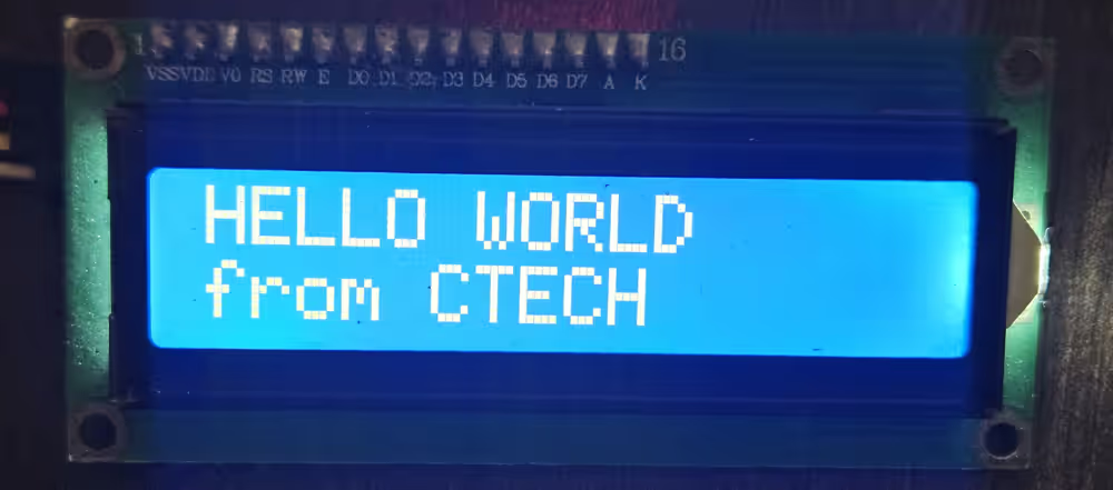
// Display Strings
  lcd_init ();
  lcd_put_cur(0, 0);
  lcd_send_string ("HELLO WORLD");
  lcd_put_cur(1, 0);
lcd_send_string("from CTECH");In the main function we will
- Initialise the LCD by calling
lcd_init()function. - Now put the cursor at the beginning of the 1st Row (0,0) and send the string “HELLO WORLD” to this location.
- Next put the cursor at the beginning of the 2nd Row (1,0) and send the string “from CTECH” to this location.
Below is the output of the above code.
Print Number
We cannot print a number directly on the LCD16x2 display. By default, the display can only show ASCII characters. Therefore, before sending a number to the LCD, we must first convert the number into its ASCII representation. After conversion, the LCD can print it just like any other character or string.
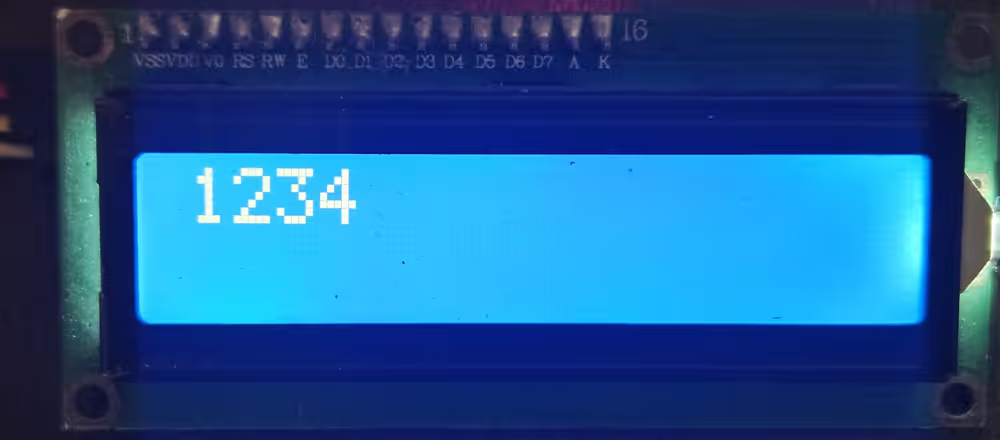
Below is the code to convert and print the number.
// Display Number
  lcd_init();
  int num = 1234;
  char numChar[5];
  sprintf(numChar, "%d", num);
  lcd_put_cur(0, 0);
lcd_send_string (numChar);In the main function we will
- Initialise the LCD by calling
lcd_init()function. - Let’s say we want to print the number 1234, which has 4 digits. Therefore, define a character buffer to store 1 extra byte, i.e 5 bytes.
- Now we will use
sprintfto convert the number to the character for and store it in the array we just defined.- The format specifier, %d, is used to convert integer values to character form.
- Next, put the cursor at the beginning of the 1st Row (0,0) and send the array.
Below is the output of the above code.
Print Floats
Just like numbers, we can not print the floats directly on the display. Therefore, we need to convert the float value to the Ascii form and then print it.
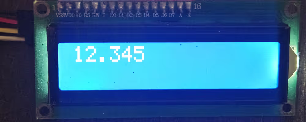
Below is the code to convert and print the float.
// Display Float
  lcd_init();
  float flt = 12.345;
  char fltChar[7];
  sprintf(fltChar, "%.3f", flt);
  lcd_put_cur(0, 0);
lcd_send_string (fltChar);In the main function we will
- Initialise the LCD by calling
lcd_init()function. - Let’s say we want to print the number 12.345. It has 6 digits, so define a character buffer to store 1 extra byte, i.e 7 bytes.
- Now we will use
sprintfto convert the float to the character for and store it in the array we just defined.- The format specifier %.3f is used to convert float values to character form, till 3 decimal places.
- Next put the cursor at the beginning of the 1st Row (0,0) and send the array.
Below is the output of the above code.
video tutorial
STM32 LCD 16×2 Video Tutorial
Prefer video? Watch the same wiring, CubeMX setup, and code in action.
Watch the VideoConclusion
This STM32 I2C LCD1602 project demonstrates how to display strings, integers, and floating-point values using just two GPIO pins. By using the PCF8574 I2C expander along with the STM32 HAL library, the design minimizes pin usage while remaining scalable, making it well suited for modern embedded and IoT applications.
Overall, the I2C-based LCD interface offers an efficient, clean, and easily extensible solution for STM32 projects. If your application requires a more traditional setup or direct GPIO control, you can also explore the parallel LCD16×2 interface tutorial for STM32 as an alternative approach.
Check out other STM32 Display Tutorials
Interface TFT display with STM32
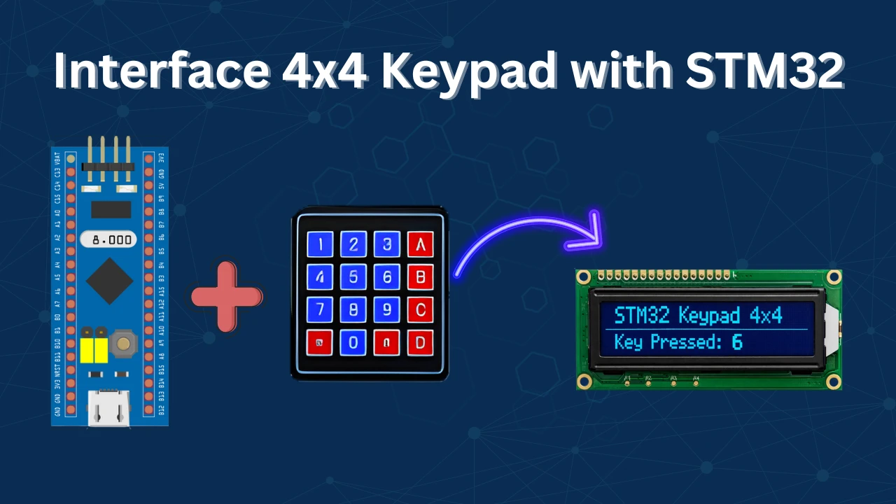
How to use 4×4 keypad with STM32

Custom characters in LCD 1602 || STM32

TouchGFX #7. How to implement on screen keyboard
How to Scroll Text on MAX7219 Dot‑Matrix with STM32 (SPI)
How to Interface SSD1306 0.96” OLED Display with TM4C123G Tiva C: Text, Shapes, and Animations

void lcd_init(void) {
HAL_Delay(50); // Wait for >40ms after power on
lcd_send_cmd(0x30);
HAL_Delay(5); // Wait for >4.1ms
lcd_send_cmd(0x30);
HAL_Delay(5); // Wait for >100us
lcd_send_cmd(0x30);
HAL_Delay(150);
lcd_send_cmd(0x02); // Set to 4-bit mode
// HAL_Delay(10);
lcd_send_cmd(LCD_FUNCTIONSET | LCD_4BITMODE | LCD_2LINE | LCD_5x8DOTS); // Function set: 4-bit mode, 2 lines, 5×8 dots
// HAL_Delay(1);
lcd_send_cmd(LCD_DISPLAYCONTROL | LCD_DISPLAYON | LCD_CURSOROFF | LCD_BLINKOFF); // Display off
lcd_send_cmd(LCD_ENTRYMODESET | LCD_ENTRYLEFT | LCD_ENTRYSHIFTDECREMENT);
// HAL_Delay(1);
lcd_clear(); // Clear display
// HAL_Delay(1);
// lcd_send_cmd(0x06); // Entry mode set: increment cursor, no display shift
// // HAL_Delay(1);
// lcd_send_cmd(0x0C); // Display on, cursor off, no blink
}
this right intialize
Hi, i am trying out the code on another controller, the i2c waveforms are correct but still sometimes lcd does not print anything. In cases where it works, there is no difference in waveforms. What may be the issue. The POT is adjusted correctly.
doesn’t write anything in the second line… (
doesn’t write anything in the second line… (
i add “i2c-lcd.h” and “i2c-lcd.c” into my project,1602 LCD can not print number(0,1,2) with ” lcd_send_data(1)”.howeverm LCD can print “string”.
displays can only print ascii characters.
You need to convert numbers into the relevant ascii character.
sprintf (buffer, “%d”, num);
lcd_send_string (buffer);
void lcd_clear (void)
{
lcd_send_cmd(0x01);
delay_ms(2);
}
//Add function
void lcd_gotoxy(unsigned char x, unsigned char y){
unsigned char xy;
if(y==0){xy=0x80;}
if(y==1){xy=0xC0;}
if(y==2){xy=0x94;}
if(y==3){xy=0xD4;}
xy=xy+x;
lcd_send_cmd (xy);
}
Hi, I want to suggest the following code for PC8574 with 9 pins (blue board)
//Rs–>P0, RW–>P1, E–>P2, D4–>P4, D5–>P5, D6–>P6, D7–>P7
void lcd_send_cmd(char cmd)
{
uint8_t cmd_t[4];
cmd_t[0]=(cmd&0xf0)|(0x04); //cmd_u ,E=1, RS=0
cmd_t[1]=(cmd&0xf0); //E=0, RS=0
cmd_t[2]=((cmd<<4)&0xf0)|(0x04); //cmd_l E=1, RS=0
cmd_t[3]=((cmd<<4)&0xf0); //E=0, RS=0
HAL_I2C_Master_Transmit(&hi2c1, SLAVE_ADDRESS_LCD, (uint8_t *) cmd_t, 4, 200);
}
void lcd_send_data(char data)
{
uint8_t data_t[4];
data_t[0]=(data&0xf0)|(0x05); //data_u , E=1, RS=1
data_t[1]=(data&0xf0)|(0x01); //E=0, RS=1
data_t[2]=((data<<4)&0xf0)|(0x05); //data_l, E=1, RS=1
data_t[3]=((data<<4)&0xf0)|(0x01); //E=0, RS=1
HAL_I2C_Master_Transmit(&hi2c1, SLAVE_ADDRESS_LCD, (uint8_t *) data_t, 4, 200);
}
thank you so much!!
hi, i follow every steps but on my lcd i see only the ligth but no word. Can you help me plese?
try to adjust the potentiometer on your lcd i2c adapter-board. This solved that problem for me
it’s work very fine. Can you help me to print the value of the potentiometer linked on ADC please?
Hi I imported the project but it will not run it keeps saying “this launch configuration requires the selected build configuration to use the MCU ARM GCC toolchain”
how do I fix this?
Hi everyone. I have a problem when my program does software reset, my LCD shows noisy characters after running LCD_init(). I have to reset it again to work properly. How can I fix it? It’s imprortant when I use IWDG
When I try to display numbers above 9, it prints it corresponding ASCII characters.How will I print a value stored in a variable which is incremented or varying.
Thanks for the tutorial.It works fine
I also wanted to print ADC values which have float and integer values.
you should use sprintf to convert the numbers to characters.
Do you have an example code for that function with the above-attached header files and source files ? Please send it or mention it if you have.
let’s say you want to convert 1234 to characters.
unsigned int num = 1234;
char buffer[4];
sprintf (buffer, “%u”, num);
does it work in mode 8bit?
You need to modify the init code as per the 8 bit initialization
also the lcd_send_cmd and data functions. There we split the data into upper and lower half, so just don’t split it and it will work
Hi, as D0 – D3 are not connected – IMHO also 8-bit mode can not work. True?
yes not with this setup. But the same code with little modification can work..
hi
I did not understand how to change the code for 8bit.
please give an example
what you mean 8 bit ?
8 bit initialization.
Can you send modified code for the “lcd_send_cmd” function?
i modify “lcd_init” function from data sheet but I could not modify the code of
“lcd_send_cmd” and “lcd_send_data”
you mean this ? https://controllerstech.com/interface-lcd-16×2-with-stm32-without-i2c/
no,this code for 8 bit mode
why 8 bit mode ? The PCF only connects to 4 data pins of the LCD. The 8 bit code won’t work
its works, but i am having problems with the brightness and it is not the potentiometer, where should i change it?
I think you should use external power source
sir i want to toggle curser set position on lcd
You are telling so many topics, you are wasting your time. We are watching you until the end, but you do not share any files. How are we going to experiment ourselves? Every download link contains ads. it still does not download. Why follow as long as you don’t provide any support here?
There are not even header and source files suitable for your program. Or you don’t even have a general program. If we get it wrong, at least somewhere, we can download your program and try it out.
But there is no file.
Sorry man. I found it . Please change the still for download button:))
I am so sorry . My fault. I did not see it.
where can download the files? I can`t see the link
now check. I am making some changes in the website… so it might have got deleted… FIXED NOW
https://controllerstech.com/wp-content/uploads/2019/12/TUT_LCD_I2C_F103_CUBEIDE.zip
ok
How can set cursor in another position?
Another way to clear the screen is:
lcd_send_cmd(1);
Cheers
wow thank you so much it work better than lcd_clear() in the library
Excellent. Worked first time. Thanks a lot.
well done, thanks
I had to use Direct manipulation on the I2C registers on my Nucleo STM32F767 to make this thing works -_-
There are slightly different I2C parts with different I2C address 0x3F for -AT and 0x27 for -T
Refer to spec and modify you code for part you have.
The PCF8574AT has I2C address as shown in this code starting with 0x3F.
The PCF8574T has different I2C address starting with 0x27.
Refer to part spec.
You may need to modify I2C address for the part you have.
hi
how can send custom character with your library?
(is it even possible)
hi again
i managed to create custom character using your library like below:
/* code
const char UserFont[8][8] =
{
{ 0x11,0x0A,0x04,0x1B,0x11,0x11,0x11,0x0E },
{ 0x10,0x10,0x10,0x10,0x10,0x10,0x10,0x10 },
{ 0x18,0x18,0x18,0x18,0x18,0x18,0x18,0x18 },
{ 0x1C,0x1C,0x1C,0x1C,0x1C,0x1C,0x1C,0x1C },
{ 0x1E,0x1E,0x1E,0x1E,0x1E,0x1E,0x1E,0x1E },
{ 0x1F,0x1F,0x1F,0x1F,0x1F,0x1F,0x1F,0x1F },
{ 0x0E,0x1F,0x11,0x11,0x13,0x17,0x1F,0x1F },
{ 0x1F,0x11,0x11,0x11,0x11,0x11,0x11,0x1F }
};
lcd_send_cmd(0x40); // Set CGRAM address counter to 0
char const *p1;
p1 = &UserFont[0][0];
for (int i = 0; i < sizeof(UserFont); i++, p1++){
lcd_send_data(*p1);
}
lcd_send_cmd(0x80);
*/
now sending character 0x00 to 0x07 displays 8 predefined custom character
Ok I will test it and include it in the code.. Do you want the reference ?
If there is anyone that can help me i send him my code. The circuit that i mounted is the same of the youtube tutorial.
Hello, i have problem with this project. Can anyone help me? I found the i2c addres with i2c scanner did with keil, not arduino: it’s 0x3F. The code is the same that i have downloaded from this site; maybe change some setting into frequency or clock because i use an stm32f767zi. Please help me.
Hi, is it possible to avoid using HAL_DELAY() in void lcd_init (void)? What else can I use in the init function instead of HAL_DEALY() ?
yeah It’s possible.. You can use that microsecond delay instead.. Or just use some empty loop
Error building…
../Core/Src/i2c-lcd.c:20: undefined reference to `hi2c1′
did you select I2C while setting up cubemx ?
Hi Everyone, I am using with stm32f072 board and have an lcd with PCF8574 converter. The project is building successfully but for some reason I do not get anything on my lcd. What could be the reason? This is the first time I am trying to send something to my lcd.
Try adjusting the potentiometer for the contrast
I have done that. I am not sure the slave address though. How can I make sure 0x4E is an appropriate one?
if you are using pcf8574 (not any other version of it) than the address is 0x4E. Read the datasheet for the address related querry
That is interesting but I have different manual – by Philips Semiconductors. I do not have that address reference in there, but for addressing I have a slave address: S 0 1 0 0 A2 A1 A0 0 A
that is how the addressing is. 0100 (4) and A2 A1 A0 pins are high by default. which makes the default address as 0x4E.
Ok, I do not know how it came but it is working now 🙂 Thank you.
Do I need to change / modify libs for sending ADC temperature results to my lcd ?
Hi, I am struggling to get it working. For some reason, am not successful. Can you share your code (vrtata@gmail.com) and wiring of the setup? It will be a great help.
For binary 01001100 , I think it should be 76 (decimal) and it means 0x4C instead of 0x4B
Yeah you are right… My bad, I’ll fix it.
Hello!
Redid the project in STM32CUBEIDE does not work. Blue pill board.
It should work. I’ll check and upload the CUBEIDE working code..
How can I send a project?
Download the project now. It works alright with CUBEIDE
I don’t understand why the code does not work. I have the address I2C = 3F.PB8-SCL, PB9-SDA.
I collected the project with this data, there are no errors. The code does not work. Other code in this configuration works. What is wrong?
If you are using PCF8574, the address is 0x4E.
I am using PCF8574AT. The I2C address scanner on the terminal shows address = 3F.
Stm32 uses the i2c protocol in a manner that the address would be (address+read/write). This way in order to write (0), the address would be 0x7E for you.
Everything began to work. In the i2c-lcd.c file I replaced #define SLAVE_ADDRESS_LCD 0x4E //., #Define SLAVE_ADDRESS_LCD 0x3F << 1 //. Thank you very much for your work.
Are you planning to make an LCD 1602 project without an I2C interface in CUBEIDE?
Sure, could do that. Nobody ever requested it so i never bothered 😁. I will do that soon.
This is very good. I will look forward to it.
Hello, Thank you for this code.I use your code, when I initialize LCD my LCD’s back-light is goes off,why this happens?could you help me?
The backlight was the issue but it’s fixed now. I don’t know what is happening in your case. Check the send command function in i2clcd.c file and confirm if it is same as below
0x0c , 0x08, 0x0c, 0x08
And data function should be 0x0d, 0x09, 0x0d, 0x09.
I’m using your code but all the i2c bus is sending are ‘Setup Write to [&] + NAK’ packets over and over and over again. I’m using salae’s logic program and an analyzer to get the data. The board is a blue pill with some chinese knockoff STM32f103c8 but it’s working as normal so far except for the code. Any ideas??
What are u using to connect lcd to the I2C ?
If it is pcf8574, are u using the address 0x4E ?
It’s an I2C backpack module for the 16×2 lcd screen. The chip is a PFC8574AT and using the arduino and some handy I2C scanner code I found that the address is 0x27 which I also placed in the code instead of your provided address.
The address for the PCF8574 is not 0x27. Don’t use the arduino one. Look at the datasheet and use the proper address. I think it’s 0x4E
It works now, my chip is PCF8574AT, the address is 7E, thanks,
I changed on backlight side, replace the transistor with 470 ohm resistor, so it’s on always…cheers…
it’s not working yet with STM32F107VCT6, will it work with 3.3V supply and bus ? thanks
What error are u facing ? Are you using pcf8574 ? Is the slave address correct ? Do the debugging and find out the error type. Only than i can help you.
And keep the vcc at 5v for the lcd
Sck and sda are connected to the microcontroller pins so they will be at 3.3v always.
Also try using pull up at sck and sda and see if it helps.
i’m having problems using it, i did an exact copy of the code, activated the I2C on cubemx and the display isn’t doing anything at all besides turning on and i already adjusted brightness, i tried to measure RW pin with multimeter and i got a 5V signal everytime i did it, so i think it’s the RW but i don’t know how i change it
Can you share your entire code with cubemx file to help@controllerstech.com
can i send my code and check it please?
best regards sir
Try downloading the code again. It’s updated just now. If it doesn’t work than contact me at admin@controllerstech.com
it doesn’t work in my 16×4 lcd, can you help me to use 16×4 lcd?
Hello, can I use your i2c-lcd library for STM32F072B-discovery? Is it ok when I replace in i2c-lcd.h #include “stm32f4xx_hal.h” for #include “stm32f0xx_hal.h”. Thank you.
yeah sure you can use it
I don’t know where i do mistake. The address of display I have default 0x4E.
/* Includes ——————————————————————*/
#include “main.h”
#include “i2c-lcd.h”
/* Private variables ———————————————————*/
I2C_HandleTypeDef hi2c1;
/* Private function prototypes ———————————————–*/
void SystemClock_Config(void);
static void MX_GPIO_Init(void);
static void MX_I2C1_Init(void);
/* Private user code ———————————————————*/
int main(void)
{
/* Reset of all peripherals, Initializes the Flash interface and the Systick. */
HAL_Init();
/* Configure the system clock */
SystemClock_Config();
/* Initialize all configured peripherals */
MX_GPIO_Init();
MX_I2C1_Init();
/* Infinite loop */
while (1)
{
lcd_init ();
lcd_send_string (“HELLO WORLD”);
HAL_Delay(100);
}
}
/**
* @brief System Clock Configuration
* @retval None
*/
void SystemClock_Config(void)
{
RCC_OscInitTypeDef RCC_OscInitStruct = {0};
RCC_ClkInitTypeDef RCC_ClkInitStruct = {0};
RCC_PeriphCLKInitTypeDef PeriphClkInit = {0};
/** Initializes the CPU, AHB and APB busses clocks
*/
RCC_OscInitStruct.OscillatorType = RCC_OSCILLATORTYPE_HSI;
RCC_OscInitStruct.HSIState = RCC_HSI_ON;
RCC_OscInitStruct.HSICalibrationValue = RCC_HSICALIBRATION_DEFAULT;
RCC_OscInitStruct.PLL.PLLState = RCC_PLL_ON;
RCC_OscInitStruct.PLL.PLLSource = RCC_PLLSOURCE_HSI;
RCC_OscInitStruct.PLL.PLLMUL = RCC_PLL_MUL6;
RCC_OscInitStruct.PLL.PREDIV = RCC_PREDIV_DIV1;
if (HAL_RCC_OscConfig(&RCC_OscInitStruct) != HAL_OK)
{
Error_Handler();
}
/** Initializes the CPU, AHB and APB busses clocks
*/
RCC_ClkInitStruct.ClockType = RCC_CLOCKTYPE_HCLK|RCC_CLOCKTYPE_SYSCLK
|RCC_CLOCKTYPE_PCLK1;
RCC_ClkInitStruct.SYSCLKSource = RCC_SYSCLKSOURCE_PLLCLK;
RCC_ClkInitStruct.AHBCLKDivider = RCC_SYSCLK_DIV1;
RCC_ClkInitStruct.APB1CLKDivider = RCC_HCLK_DIV1;
if (HAL_RCC_ClockConfig(&RCC_ClkInitStruct, FLASH_LATENCY_1) != HAL_OK)
{
Error_Handler();
}
PeriphClkInit.PeriphClockSelection = RCC_PERIPHCLK_I2C1;
PeriphClkInit.I2c1ClockSelection = RCC_I2C1CLKSOURCE_HSI;
if (HAL_RCCEx_PeriphCLKConfig(&PeriphClkInit) != HAL_OK)
{
Error_Handler();
}
}
/**
* @brief I2C1 Initialization Function
* @param None
* @retval None
*/
static void MX_I2C1_Init(void)
{
hi2c1.Instance = I2C1;
hi2c1.Init.Timing = 0x00101D2D;
hi2c1.Init.OwnAddress1 = 0;
hi2c1.Init.AddressingMode = I2C_ADDRESSINGMODE_7BIT;
hi2c1.Init.DualAddressMode = I2C_DUALADDRESS_DISABLE;
hi2c1.Init.OwnAddress2 = 0;
hi2c1.Init.OwnAddress2Masks = I2C_OA2_NOMASK;
hi2c1.Init.GeneralCallMode = I2C_GENERALCALL_DISABLE;
hi2c1.Init.NoStretchMode = I2C_NOSTRETCH_DISABLE;
if (HAL_I2C_Init(&hi2c1) != HAL_OK)
{
Error_Handler();
}
/** Configure Analogue filter
*/
if (HAL_I2CEx_ConfigAnalogFilter(&hi2c1, I2C_ANALOGFILTER_DISABLE) != HAL_OK)
{
Error_Handler();
}
/** Configure Digital filter
*/
if (HAL_I2CEx_ConfigDigitalFilter(&hi2c1, 0) != HAL_OK)
{
Error_Handler();
}
/* USER CODE BEGIN I2C1_Init 2 */
/* USER CODE END I2C1_Init 2 */
}
/**
* @brief GPIO Initialization Function
* @param None
* @retval None
*/
static void MX_GPIO_Init(void)
{
/* GPIO Ports Clock Enable */
__HAL_RCC_GPIOB_CLK_ENABLE();
}
Did you find mistake?
I use STM32F103C8 + PCF8574A + Keil-5, does not work.
The program scans and finds the address 0x3F.
Works well with STM32F103C8 + PCF8574A + Arduino IDE using address 0x3F.
Works well STM32F103C8 + SSD1306 + Keil-5.
Does anyone have an idea what the problem is?
Regards
use the address 0x4E
i try it use 0x4E and others address but can’t work too,
exactly me too. did you have any solution for your problem? all of my problem is similar you. and i dont know why. if you have any suggestion please tell me.
best regards
exactly me too. did you have any solution for your problem? i have problem like him. and i dont know why. if you have any suggestion please tell me. i tested lots of addresses but i did not get any answer.
best regards
1. If you are using pcf8574, the default address is 0x4E, so don’t test anything else.
2. I have updated the code here now it works with CUBEIDE by default. If u want to use keil, you have to create project and than unclude those 2 files.
Everything is working properly. I have rechecked it.
I downloaded your code and tried executing but its not working for me. My setup is STM32F103C8 + PCF8574T + STM32CubeIDE. Any idea what could be the problem?
Make sure the contrast is set properly. Most of the times, it is working but you can’t see because of contrast.
You can try using slave address 0x7E
It was not working for me. What I realized is the execution is going into infinite loop at HAL_Delay(50). Any inputs on why this could be? Preemption Priority for System tick timer is set to 0.
Check your system setup. Looks like some problem with the clock setup. Before attempting this, try blinking the LED.
It was the clock issue. Now I do not have issues with HAL_Delay. The program runs but am unable to get any output on either the display or LogicAnalyzer. I have a feeling I am doing something stupid in my wiring. Your exact code does not produce any results. Need help with verifying my wiring. Is there a diagram I can refer to. Now am obsessed with making this work.
Working for me. Was a faulty bluepill
What did you do to work
I do not know why. But for some reason the code doesn’t work from I2C1. I changed the bluepill chip. There is no problem with the hardware. It works fine from I2C2.
Thanks for your code it works even with a 20×4 display with some changes.
I have a question: Why does your code work without the required waitings between the init commands?
The datasheet says that you have to wait more tha 4.1 ms between the first instructions.
Thanks
I never used delay after init not here not even in pic and arm7.. Things works sometimes
hi how to write code for scrolling display for 20*4 now i am able to write but it is improper please help me in the issuse
I can’t thank you enough for this lib!
Such a great and working lib and so simple!!!
Feel free to contact me for colaboration, I’d love to!
JS
Great tutorials/examples (not only this one). Thanks for sharing.
Can you give an estimate of the refresh rate when writing all 2×16 characters. Is it 1 sec. to write all characters or 0.1 sec.?
Do you consider such a display setup an acceptable debugging option?
I’ve got one question.
How to use it it other commands, for example command to clear screen ?
Can I find anywhere list of hex code for functions ?
To get the commands just google lcd 16×2 commands.
To use it, there is a function available i.e. lcd_send_cmd (cmd);
for eg to clear screen, type lcd_send_cmd (0x01);
I wrote to you in YT but its proper place . When you initialize LCD you must send 4-bit mode at first with delay
void lcd_init (void)
{
uint8_t i=0;
HAL_Delay(100);
for(i=0;i<3;i++)//sending 3 times: select 4-bit mode
{
lcd_send_cmd(0x03);
HAL_Delay(45);
}
lcd_send_cmd (0x02);
HAL_Delay(100);
lcd_send_cmd (0x28);
HAL_Delay(1);
lcd_send_cmd (0x0c);
HAL_Delay(1);
lcd_send_cmd (0x80);
HAL_Delay(1);
}
and some additional function to set proper location on screen :
void lcd_print_x_y(uint8_t line , uint8_t row, char *str )
{
if (line == 0 ){
uint8_t line_x_y = 0x80 + row ;
lcd_send_cmd(line_x_y);
while (*str) lcd_send_data (*str++);
}else if (line == 1 ){
uint8_t line_x_y = 0x80 |( 0x40 + row) ;
lcd_send_cmd(line_x_y);
while (*str) lcd_send_data (*str++);
}
}
Nice work
Could you send me the library that you have used ( i2c-lcd )
You can download the code.. Libraries are inside it in SRC and INC folders
Would you know how to insert special characters in CGRAM in this I2C communication to the LCD?
Thank you very much PawelDNB (even after 4 years)!
Using the old initalization I faced the problem that from time to time
the display was showing crap after power up.
With your initalization routine the error disappeared!
Nice.