
Home ▸ Uncategorized ▸
Updated On: September 28, 2026
CANopen with STM32: Understanding the RPDO Protocol
This is Part 6 of the CANopen with STM32 series. In Part 5, we covered the SDO protocol and saw how the master reads and writes objects inside a node’s object dictionary, one object at a time.
In this part, we move on to PDO, or Process Data Object. PDO solves two problems that come up when SDO is the only tool available:
- Reading several objects in one message
- Keeping data moving continuously between the master and the node.
We will look at how PDO differs from SDO, and how objects are mapped into a PDO. Then we will map three objects into an RPDO and test it on our STM32 node using TSMaster.
I am using the same STM32H562 project from the earlier parts of this series. We will modify a few things in today’s project, so the objects can be successfully mapped to the PDO.
This is Part 6 in the STM32 CANopen series. You can check the other tutorials below:
- PART 1: Understanding CANopen protocol
- PART 2: Configuring CAN and Adding I-CUBE-CANOPEN
- PART 3: Understanding the Object Dictionary
- PART 4: Understanding the NMT Protocol
- PART 5: Understanding the SDO Protocol
CANopen with STM32: Understanding the RPDO Protocol — Video Tutorial
This video explains how PDO differs from SDO, how objects are mapped into an RPDO, and how each mapping entry encodes the index, sub-index, and length of an object. We then configure the mapping in the Device Designer, update the object dictionary files in the STM32 project, and test the RPDO live on the STM32 node using TSMaster.
What Is PDO in CANopen
SDO works well for configuration and reading/writing objects, but it has two limits that show up once a project grows. The first limit is that SDO can only read or write one object at a time. If the master needs to update three separate objects, it has to send three separate SDO commands, one after another. The second limit is continuity. SDO does not transmit data on its own. If the master wants the node to keep sending updated data, it has to keep requesting it, again and again, and the node only responds when it is asked.
PDO removes both of these limits. A single PDO message can carry the data for several objects at once, as long as those objects have been mapped into that PDO ahead of time. A PDO can also be set up so that the node transmits its data on its own, without the master having to request it every time. This makes PDO the protocol of choice for real-time process data, while SDO stays the protocol of choice for configuration and one-off reads and writes.
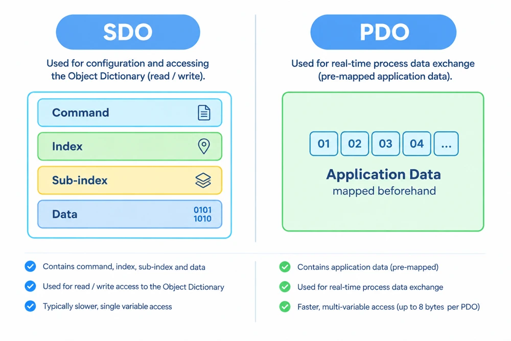
The structure of the two messages reflects this difference clearly. An SDO message always carries a command byte, followed by the index and sub-index of the object, followed by the data. A PDO message carries none of that. It only carries data, packed one after another according to the mapping that was configured beforehand. The diagram below shows this side by side.
Types of PDO
There are two directions a PDO can move in, and CANopen names them from the point of view of the node rather than the master. This naming convention is a common point of confusion, so it is worth remembering clearly from the start. Whatever the node does with the data is what names the PDO, regardless of which side actually configured it or triggered it.
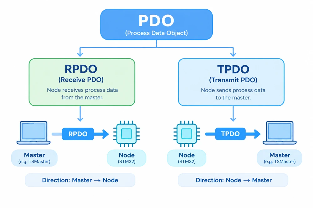
An RPDO, or Receive PDO, is used when the node receives data from the master. The master decides what to send and when to send it, and the node’s job is simply to unpack the incoming message and store each mapped value into the correct object.
A TPDO, or Transmit PDO, is used when the node transmits data to the master. Here the node is the one deciding when to send, based on its own transmission type and timing settings, and the master’s job is to listen for these messages and read the mapped values out of them. This is also what makes TPDO useful for the continuity problem mentioned earlier, since a TPDO can be configured to transmit automatically, without the master requesting for it every time.
Both RPDO and TPDO reuse the same underlying ideas covered in the rest of this part: a communication parameter that defines the CAN ID and timing, and a mapping parameter that defines which objects are packed into the message and in what order. The only difference between the two is the direction the data travels.
This tutorial covers only RPDO, where we send data from the master to the STM32 node. TPDO is covered in a separate tutorial of this series.
RPDO Parameters
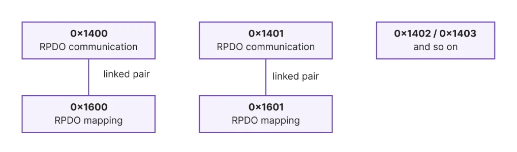
The CANopen library we are using already provides four RPDOs and four TPDOs by default. Each RPDO is described by two related objects: a communication parameter and a mapping parameter.
The communication parameters for the four RPDOs sit at indexes 0x1400 to 0x1403. Each one has five sub-indexes.
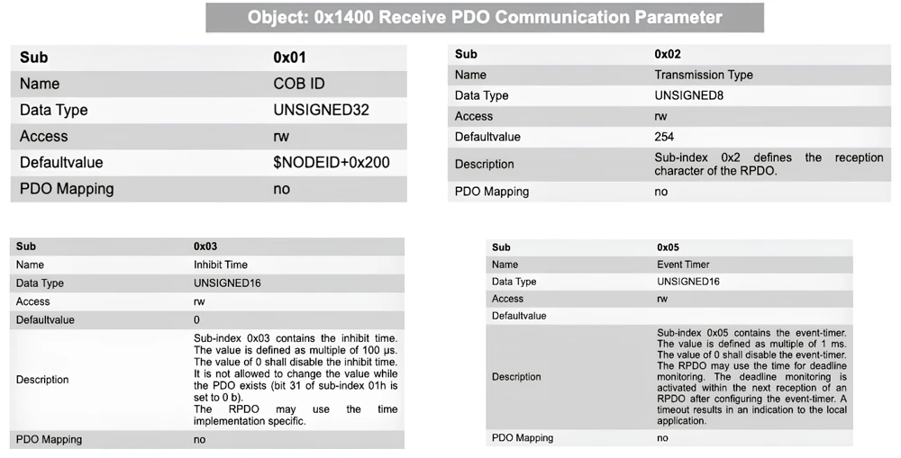
- Sub-index 1 is the COB-ID, which is the CAN identifier this RPDO listens on. By default, this is set to the node ID plus
0x200(for RPDO at 0x1400). so on our node with node ID 1, the first RPDO uses CAN ID0x201. - Sub-index 2 is the transmission type, which controls when the node processes the incoming data. The default value here is
254, which means the RPDO is processed as soon as the CAN frame arrives, without waiting for a synchronization signal. - Sub-index 3 is the inhibit time, which sets the minimum time that must pass between two consecutive messages, and is mainly relevant for TPDOs rather than RPDOs.
- Sub-index 5 is the event timer, which can be used to detect that expected messages have stopped arriving.
The mapping parameters sit at indexes 0x1600 to 0x1603, and each one is tied to the communication parameter at the matching position. The mapping parameter at 0x1600 works together with the communication parameter at 0x1400, the one at 0x1601 works with 0x1401, and so on.
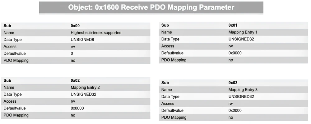
Sub-index 0 of a mapping parameter holds the number of objects mapped into that RPDO. By default, this is 0, since nothing has been mapped yet. From sub-index 1 onward, each entry is a 32-bit value that identifies one mapped object, and this is where the mapping itself is defined.
PDO Mapping Entry Format
Each mapping entry under 0x1600 is a single 32-bit value, but it actually packs three separate pieces of information: the index of the object, its sub-index, and its length in bits. This is what lets the node know which object to place at which position inside the PDO data, and how many bytes to use for it.
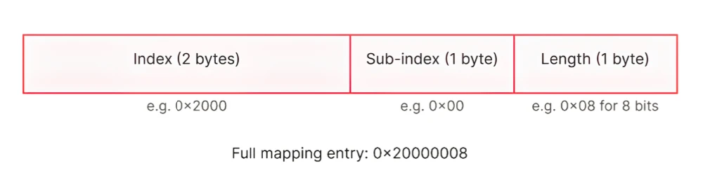
The highest two bytes of the 32-bit value hold the index of the object. The next byte holds the sub-index. The lowest byte holds the length of the object in bits. For example, an 8-bit object at index 0x2000, sub-index 0, is encoded as 0x20000008. A 16-bit object at index 0x2001 is encoded as 0x20010010, since 0x10 is 16 in hexadecimal. A 32-bit object at index 0x2002 is encoded as 0x20020020, since 0x20 is 32 in hexadecimal.
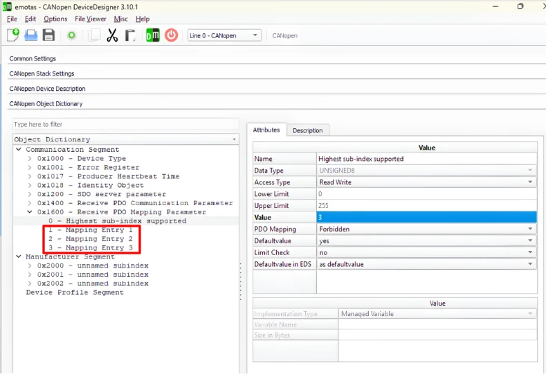
Once we understand how the entries are built, the values under 0x1600 are easy to read. Each value tells the node which object to use, which sub-index of that object to read, and how many bits of data to take. The node then places that data at the next available position inside the PDO payload.
Configure RPDO Mapping
We are going to configure the mapping using the CANopen Device Designer, the same tool we used in Part 3 of this series. We cannot load our existing project into it, since we already found that the evaluation version cannot regenerate an updated project from a modified one. Instead, we create a new project for this configuration step.
The steps to configure and generate the RPDO mapping are as follows.
- Set the node ID to 1 in the new project, since this value is needed for project generation.
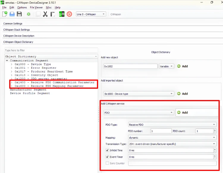
- Go to the object dictionary, select the communication segment, and add a CANopen service of type PDO. Choose the receive direction, leave the PDO number at 1, and set the PDO count to 1 for this demonstration.
- Set the mapping type to dynamic mapping, and leave the transmission type at 254, so the RPDO is processed as soon as it arrives, without needing a trigger signal.
- Leave the inhibit time and event timer enabled with their default settings, so the generated project matches the structure the library already uses. Click Add to create the PDO, which adds two new indexes:
0x1400for the communication parameter and0x1600for the mapping parameter.
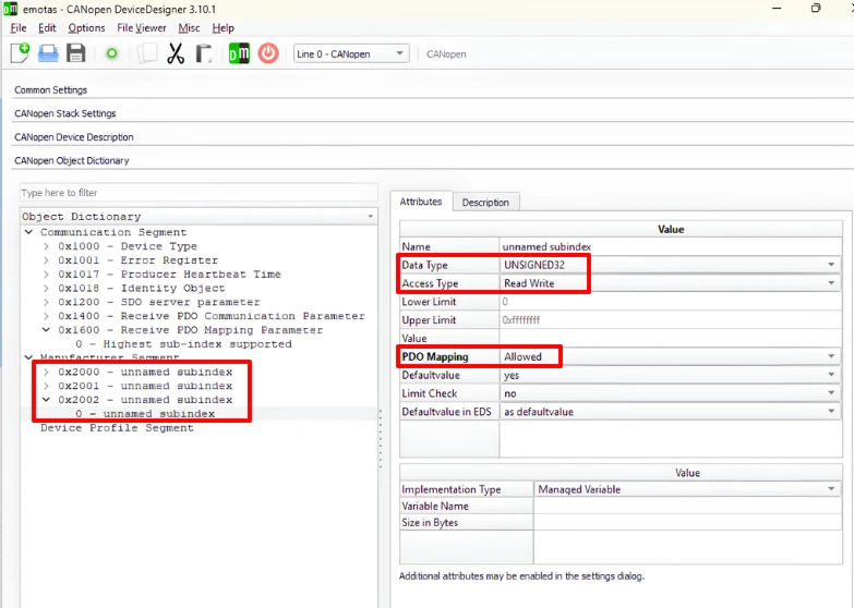
- Go to the manufacturer segment and create three objects: an 8-bit unsigned integer at
0x2000, a 16-bit unsigned integer at0x2001, and a 32-bit unsigned integer at0x2002. Set read and write access on each one, and make sure PDO mapping is enabled for each one, since an object cannot be mapped without this setting.
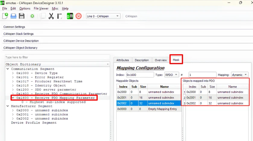
- Open the mapping section for the RPDO at
0x1600. The three objects appear here because PDO mapping was enabled for them. Double-click each one, starting with0x2000, then0x2001, then0x2002, to add them to the mapping.
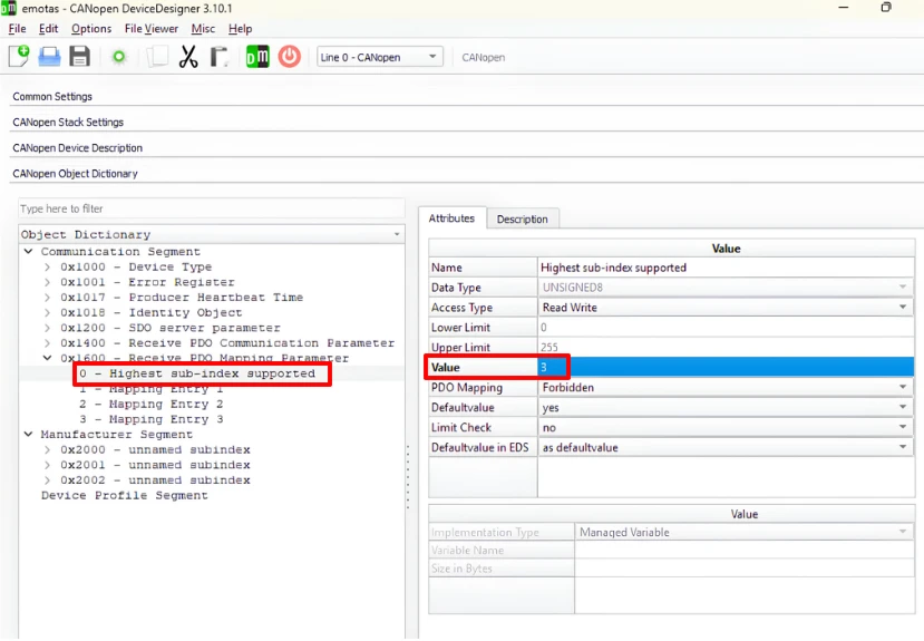
- Once all three objects are mapped, we need to update the sub-index 0 under
0x1600to 3, since there are now three mapped entries.
Save the project to a new folder and click Generate to produce the updated project files.
Update Generated Files
The gen_define.h file does not need any changes. The object count and the RPDO and TPDO counts in this file are already set correctly by the library, We have not added any new objects, the objects at index 0x2000, 0x2001 and 0x2002 are already defined in the library by default.
The gen_objdict.c file needs a few edits. The variable definitions do not change, since no new variables were added. However, the constant definitions do change, because the three 32-bit mapping values we just created need to be added to the existing 32-bit constant array in our project.
static CO_CONST UNSIGNED32 CO_CONST_STORAGE_CLASS	od_const_u32[23+3] = {
	(UNSIGNED32)0UL,
	(UNSIGNED32)128UL,
	(UNSIGNED32)100000UL,
	(UNSIGNED32)65536UL,
	(UNSIGNED32)131072UL,
	(UNSIGNED32)196608UL,
	(UNSIGNED32)793UL,
	(UNSIGNED32)2069UL,
	(UNSIGNED32)65537UL,
	(UNSIGNED32)1UL,
	(UNSIGNED32)129UL,
	(UNSIGNED32)130UL,
	(UNSIGNED32)131UL,
	(UNSIGNED32)1536UL,
	(UNSIGNED32)1408UL,
	(UNSIGNED32)512UL,
	(UNSIGNED32)768UL,
	(UNSIGNED32)1024UL,
	(UNSIGNED32)1280UL,
	(UNSIGNED32)2147484032UL,
	(UNSIGNED32)2147484288UL,
	(UNSIGNED32)2147484544UL,
	(UNSIGNED32)2147484800UL,
	(UNSIGNED32)536870920UL,  // 23
	(UNSIGNED32)536936464UL,  // 24
(UNSIGNED32)537002016UL}; // 25Here I have added 3 new constant values to the od_const_u32 array. These values, 536870920, 536936464 and 537002016 are taken from the gen_objdict.c file from project generated by the Canopen Device Designer. These are the same values described earlier: 0x20000008, 0x20010010, and 0x20020020.
The object description for 0x1400 can be left as it is, since the values generated for the communication parameter match what our library already uses. The object description for 0x1600 does need changes.
	{ (UNSIGNED8)0u, CO_DTYPE_U8_RMAP  , (UNSIGNED16)1u, CO_ATTR_NUM | CO_ATTR_READ | CO_ATTR_WRITE | CO_ATTR_DEFVAL,  (UNSIGNED16)1u},/* 0x1600:0*/
	{ (UNSIGNED8)1u, CO_DTYPE_U32_RMAP , (UNSIGNED16)1u, CO_ATTR_NUM | CO_ATTR_READ | CO_ATTR_WRITE | CO_ATTR_DEFVAL,  (UNSIGNED16)23u},/* 0x1600:1*/
	{ (UNSIGNED8)2u, CO_DTYPE_U32_RMAP , (UNSIGNED16)1u, CO_ATTR_NUM | CO_ATTR_READ | CO_ATTR_WRITE | CO_ATTR_DEFVAL,  (UNSIGNED16)24u},/* 0x1600:2*/
{ (UNSIGNED8)3u, CO_DTYPE_U32_RMAP , (UNSIGNED16)1u, CO_ATTR_NUM | CO_ATTR_READ | CO_ATTR_WRITE | CO_ATTR_DEFVAL, (UNSIGNED16)25u},/* 0x1600:3*/Sub-index 0 must be updated to hold the value 3 instead of 0. Look closely at the end of the first line. The 1u in the last field is not “1 entry” — it’s an index pointing into od_const_u8. The stack fetches whatever value is stored at that position, which is 3 in my case, so this descriptor correctly reports 3 entries.
The three mapping entries also need to point to the correct positions inside the od_const_u32 array. Therefore I have updated the positions to 23, 24 and 25.
The object dictionary assignment for these three objects does not need any changes. We have not added any new objects here, and the library has already assigned all the pre-added objects by default.
Test RPDO with TSMaster
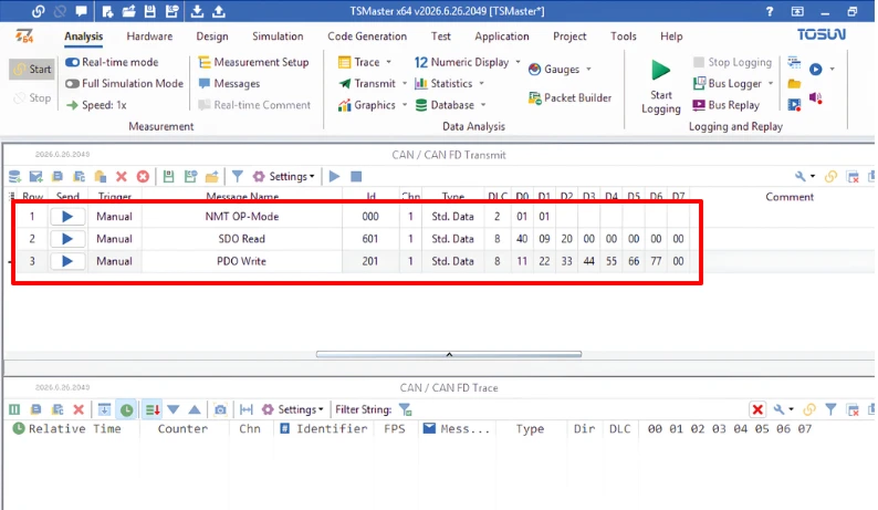
With the project flashed, we can test the RPDO using TSMaster. I am going to use three command here: an NMT command to put the node into the operational state, an SDO read command to check the object values before and after the test, and the RPDO write itself.
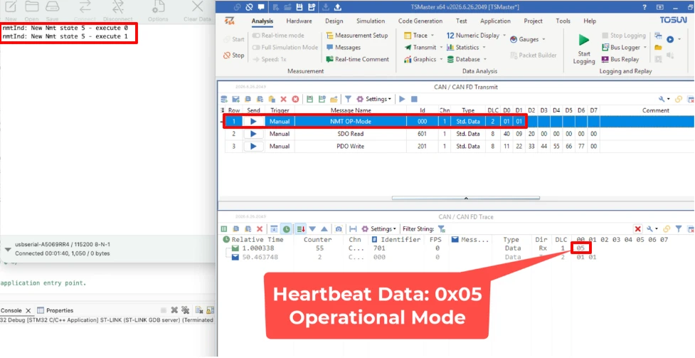
PDO communication does not work while the node is in the pre-operational state, so the first step is always to send the NMT command to move the node into operational mode. Once this is done, the node’s heartbeat value changes to 0x05, confirming the operational state.
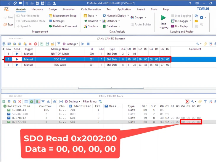
Before sending any RPDO data, we will read the three objects with SDO. The response shows that all three objects currently hold the value 0.
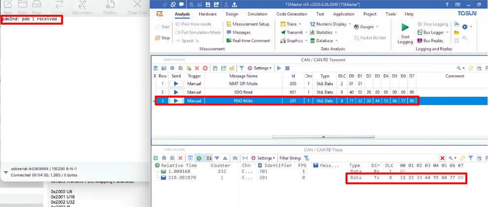
Now we will send the RPDO write. We will use the CAN ID 0x201, because this RPDO uses the communication parameter at 0x1400, and the COB-ID of that parameter is the node ID plus 0x200. In the data field, we only need to enter the raw values that we want to store, so there is no command byte or index involved. Based on the mapping we configured, the first byte will go into the 8-bit object at 0x2000. The next two bytes will go into the 16-bit object at 0x2001, and the last four bytes will go into the 32-bit object at 0x2002. In total, we will send seven data bytes in a single message.
After sending this single RPDO message, we will read the three objects back using SDO.
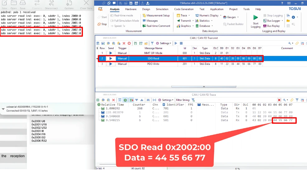
The response shows that each object now holds the value that we sent for it. This confirms that the RPDO updated all three objects using one message, instead of three separate SDO write commands.
We are still using SDO to verify the data in this test, because the STM32 node cannot transmit any data on its own yet. This becomes possible with the TPDO, where the node sends the data of multiple objects in a single message without waiting for a request. We will cover the TPDO in an upcoming part of this series.
Conclusion
We looked at why PDO exists alongside SDO in CANopen, and how it solves the two limits of SDO: reading or writing only one object per message, and needing a fresh request every time data is needed. We also went through the structure of the RPDO communication and mapping parameters, and saw how each mapping entry encodes the index, sub-index, and length of an object into a single 32-bit value.
We then configured an RPDO mapping three objects using the Device Designer, updated the generated object dictionary files in our STM32 project, and confirmed the mapping worked using TSMaster, both in the operational state and in the pre-operational state.
In the next part of this series, we will assign an object to an actual STM32 variable, so that the data received through an RPDO can control the hardware connected to the STM32. After that, we will cover the TPDO, where the STM32 node transmits the data collected from its hardware to the master on its own, without waiting for a request.
Download STM32 CANopen RPDO Project Files
CubeMX project files and HAL source code with the RPDO mapping for the objects at 0x2000, 0x2001, and 0x2002, tested on real hardware. Free to download — support the work if it helped you.
Browse More STM32 CANopen Tutorials

Subscribe
Login
0 Comments
Newest

