
Home ▸ Uncategorized ▸
Updated On: September 22, 2026
CANopen with STM32: Understanding the SDO Protocol
This is Part 5 of the CANopen with STM32 series. In Part 4, we looked at the NMT protocol and saw how it controls the different states a node can be in.
In this part, we move on to another protocol used in CANopen, called SDO, or Service Data Object. SDO is what lets a master read or write objects inside a node’s object dictionary. We will go through the command format used for both reading and writing, understand what each byte in the command means, and then test it live on our STM32 node using TSMaster software running on the computer.
I am using the same STM32H562 project from the earlier parts of this series.
This is Part 5 in the STM32 CANopen series. You can check the other tutorials below:
- PART 1: Understanding CANopen protocol
- PART 2: Configuring CAN and Adding I-CUBE-CANOPEN
- PART 3: Understanding the Object Dictionary
- PART 4: Understanding the NMT Protocol
CANopen with STM32: Understanding the SDO Protocol — Video Tutorial
This video walks through the CANopen SDO protocol on STM32 — the read and write command format, how the command byte encodes data length, and what a success or abort response looks like. We then test it live on the STM32 node using TSMaster, reading and writing objects in the object dictionary.
What Is SDO Communication in CANopen
SDO stands for Service Data Object. It’s the protocol CANopen uses whenever the master needs to read or write something inside a node’s object dictionary. Think of it as a simple request-and-response conversation. The master asks for something, or tells the node to store something, and the node replies back confirming what happened.
We already used SDO commands in the earlier parts of this series, without really looking at how they’re built. Now it’s time to understand exactly what’s happening byte by byte.
SDO works on a simple client-server model. The master is always the client, and the node is always the server. This means the node never sends an SDO message on its own. It only replies once the master asks for something. Compare this to the heartbeat, which the node keeps sending out by itself, and you’ll see the difference.
Every SDO exchange is also a one-to-one conversation. The master talks to exactly one node at a time, using that node’s own CAN ID. This is different from an NMT command, which can be broadcast to every node on the bus at once. SDO is never broadcast. It’s always addressed, and it always expects a reply back before the transaction is considered done.
You’ll mostly reach for SDO during configuration and setup, or when you need to check something on a node without disturbing its normal operation. Things like reading a vendor ID, checking firmware details, setting a heartbeat interval, or writing a calibration value into an object all go through SDO. It’s not meant for fast, repeated data exchange. That job belongs to PDO, which we’ll get into later in this series. SDO is slower, but it’s also far more flexible, since it can reach any object at any index, not just the ones that have been mapped ahead of time.
One more thing worth knowing upfront: every SDO request gets a response, one way or another. Either the node sends back the data we asked for, confirms our write went through, or sends an abort telling us something was wrong with the request. There’s no such thing as an SDO message that just gets sent into the void. That’s what makes it reliable enough to use for configuration, even though it’s not built for speed.
SDO Read Command Format Explained
Every SDO command the master sends uses the CAN ID 0x600 + node ID. Our STM32 node has node ID 1, so any command going to it uses CAN ID 0x601.
The command itself is 8 bytes long, and here’s what each byte means for a read request:
- Byte 1 – Command byte: For a read request, this is always
0x40. This one byte is what tells the node that the request is a read request. No matter which object we’re asking about, this first byte doesn’t change for a read request. It’s only the response that changes, depending on how much data comes back. - Byte 2 & 3 – Index: The index of the object we want to read. Every object in the dictionary has a 16-bit index, so it needs 2 bytes to represent. The command is sent LSB first, so the lower byte goes first, followed by the higher byte. For example, if you want to read index
0x2000, you write00 20, since00is the least significant byte and20is the most significant byte. - Byte 4 – Sub-index: For a simple variable, this is just
0. Some objects in the dictionary aren’t single values, they’re arrays or records with multiple entries under the same index. In that case, the sub-index tells the node exactly which entry you want. A variable, on the other hand, only ever has one entry, so its sub-index is always0. - Byte 5 to 8 – Unused: These are just sent as zeros for a read request. A read command doesn’t need to carry any actual data, since we are asking the node to send data back, not giving it any. These last 4 bytes exist only to keep the command a fixed length of 8 bytes, which is what the CAN frame expects.
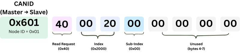
So if we want to read the object at index 0x2000, sub-index 0, the command bytes would look like:40 00 20 00 00 00 00 00
SDO Read Response Format
Once the node gets this read request, it sends a response. This response always uses CAN ID 0x580 + node ID, so in our case, that’s 0x581.
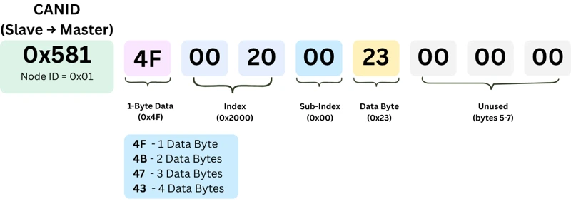
The first byte of the response tells us how many data bytes are coming back:
| Response Byte | Data Bytes Sent |
|---|---|
| 0x4F | 1 byte |
| 0x4B | 2 bytes |
| 0x47 | 3 bytes |
| 0x43 | 4 bytes |
After this first byte, the response carries the index, the sub-index, and then the actual data. How many data bytes we get back just depends on the size of the object we asked for. If we read an 8-bit object, we will get 1 byte and if we read a 32-bit object, we will get 4 bytes.
How the SDO Command Byte Encodes Data Length
We just saw that there are different command bytes for different data length. Let’s understand how this is decided.
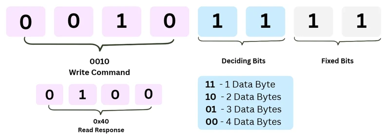
The higher nibble of the command byte tells us the operation. 0010 (0x20) means the command is for write operation, and 0100 (0x40) means it is a response to a read command.
The lower nibble of the command byte tells us how many data bytes are involved. Bit 0 and bit 1 here always stay fixed at 1, whereas bits 2 and 3 are the ones that actually change, and their combination decides the byte count:
| Bit 3 | Bit 2 | Data Bytes |
|---|---|---|
| 1 | 1 | 1 byte |
| 1 | 0 | 2 bytes |
| 0 | 1 | 3 bytes |
| 0 | 0 | 4 bytes |
This same rule applies whether the master is writing data, or the node is sending back a read response. Once this is clear, the command bytes stop looking random and start making sense.
SDO Write Command Format Explained
Writing works the same way as reading, just with a different command byte is used here.
- 1 data byte (8-bit write): command byte
0x2F - 2 data bytes (16-bit write): command byte
0x2B - 4 data bytes (32-bit write): command byte
0x23
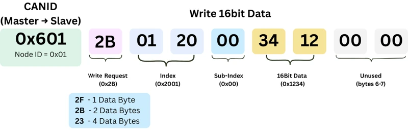
After the command byte, you send the index (LSB first), the sub-index, and then the data itself. For example, writing 0x12345678 into a 32-bit object means sending the data as 78 56 34 12, since CANopen always sends the least significant byte first.
The response to a write is much simpler than a read response, and it doesn’t change based on how many bytes we write. The command byte of the response signifies whether the write is success or not:
0x60– the write succeeded0x80– the write failed (this is called an SDO abort)
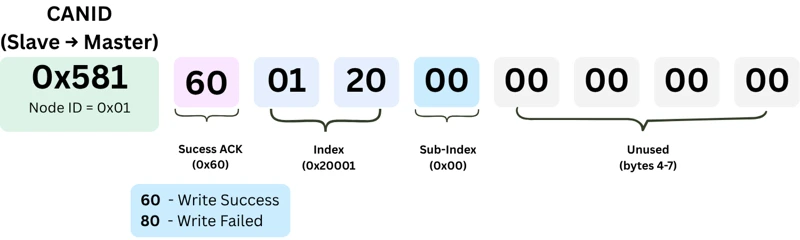
An abort usually means you sent the wrong number of data bytes for that object. Try to write 2 bytes into an 8-bit object, and the node will reject it every time.
Testing SDO Read and Write on STM32 with TSMaster
Now we will see this working on actual hardware. I have the same object dictionary from the earlier parts, TSMaster connected on a virtual machine, and the STM32 board flashed with the CANopen project.
First, let’s read the Vendor ID at index 0x1018, sub-index 1. This is a 32-bit register, so we expect 0x43 back along with 4 data bytes.
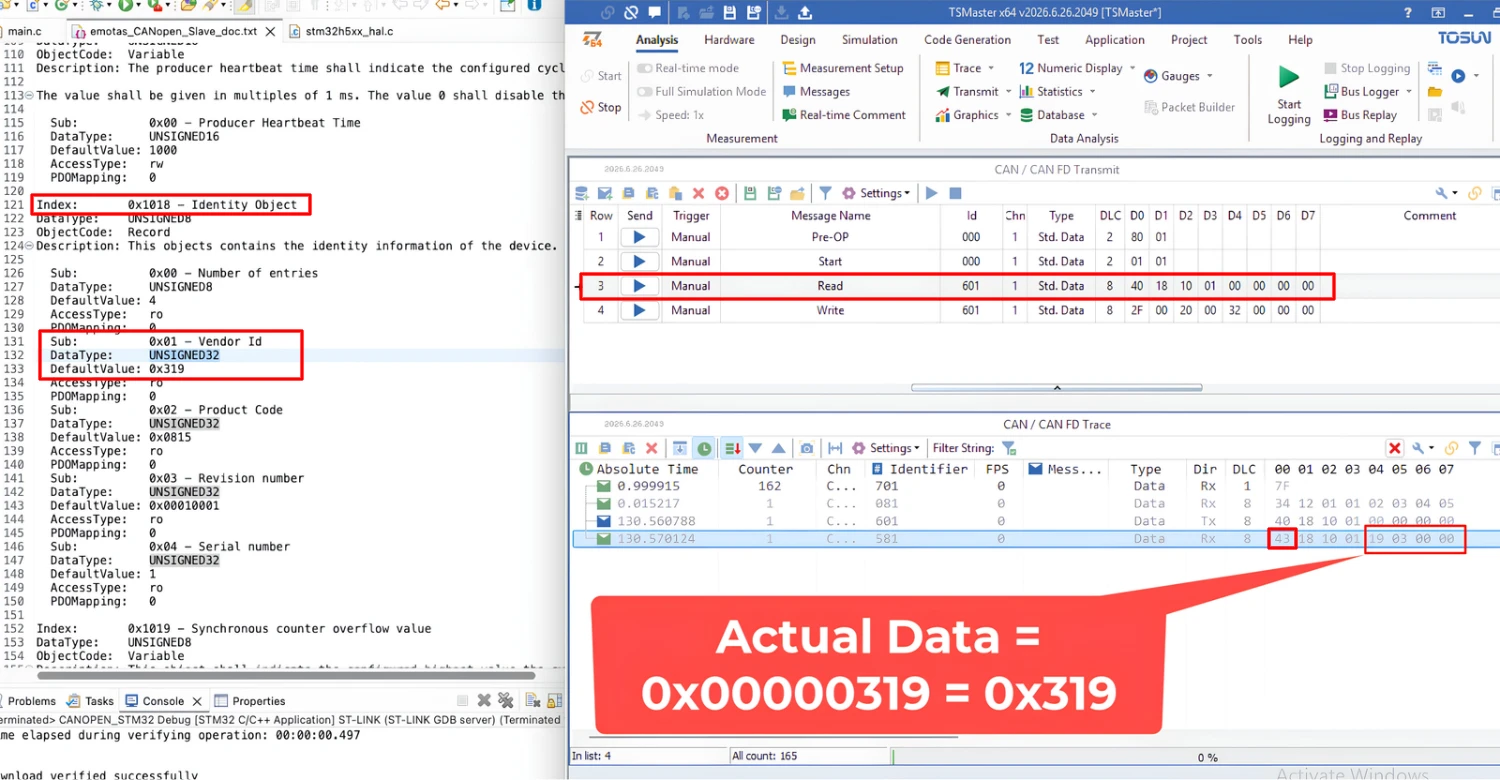
Sending the read command gives us back 19 03 00 00. Rearranging those last 4 bytes (LSB first) gives 0x00000319, which matches the vendor ID value inside the object dictionary.
Next, let’s read the Producer Heartbeat Time at index 0x1017, sub-index 0. This is a 16-bit register, so we expect 0x4B back along with 2 data bytes.
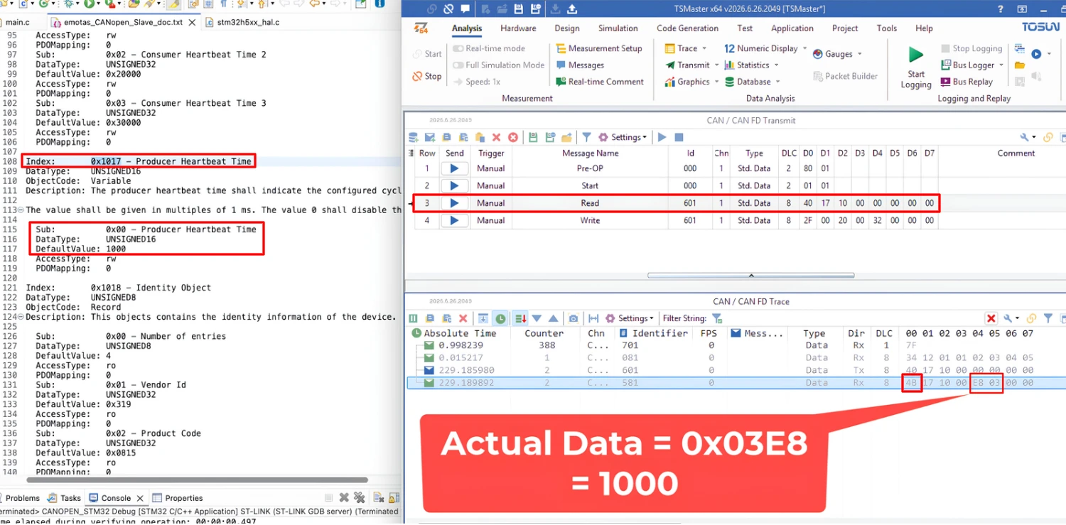
The response comes back as E8 03, and rearranging those bytes gives 0x03E8, which is 1000 in decimal. This is the same data stored inside this object in the object dictionary.
Similar to read, we can also write data inside an object. I am going to write a single byte data to the object at index 0x2000, which lies in our application region.
For writing single byte data, we need to send the command byte 0x2F, followed by the 2 bytes of the index number and 1 byte of the sub-index, and finally 1 byte of the data. Here I am writing 0x32 to object located at 0x2000:00.
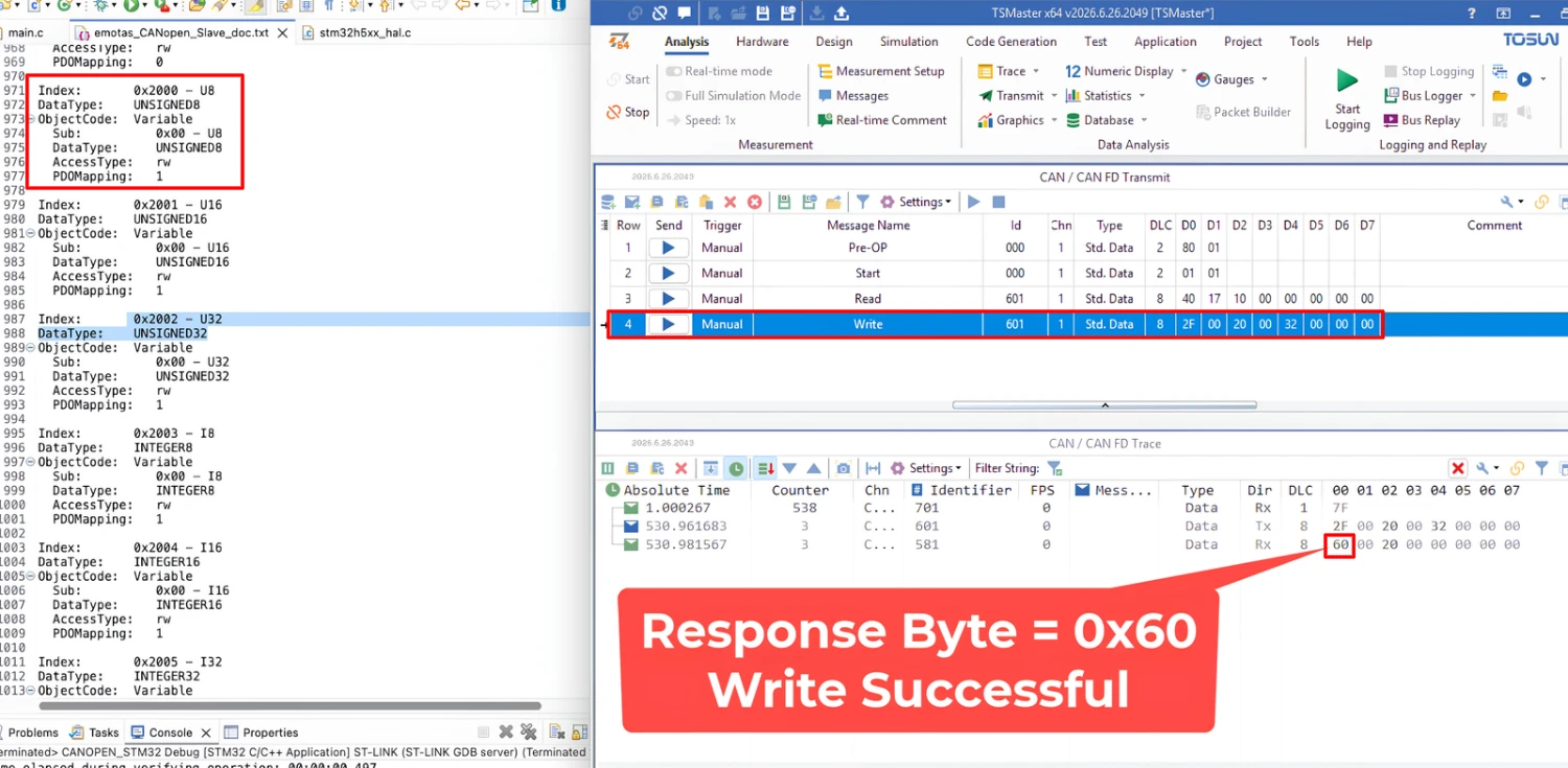
The response sent by the node contains the command byte 0x60, indicating that the write is successful.
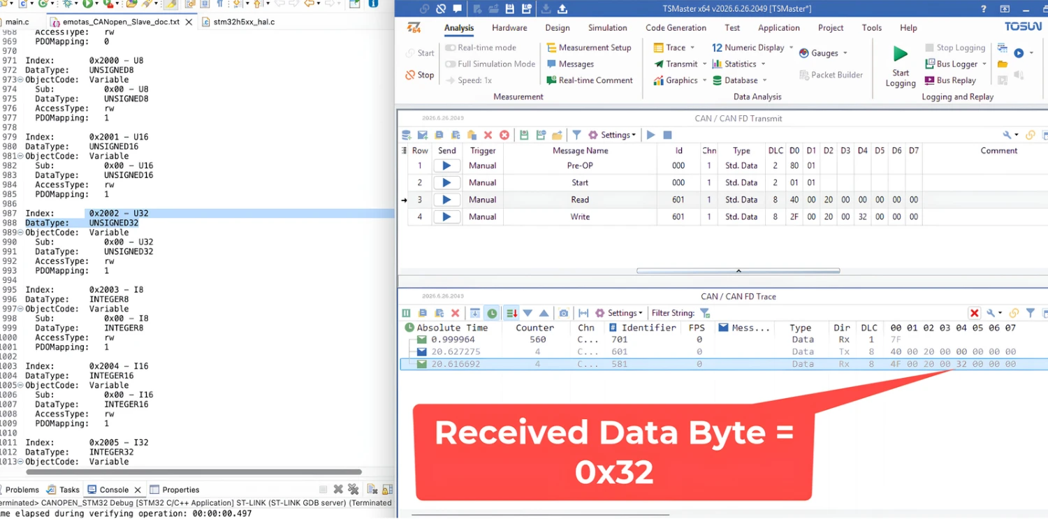
If we read back the data stored inside the object 0x2000:00, we should get 0x32, the same data byte we we wrote.
Now I am going to write 32-bit data inside the object 0x2000:00. The object is 32-bit in size and therefore we need to send 4 data bytes.
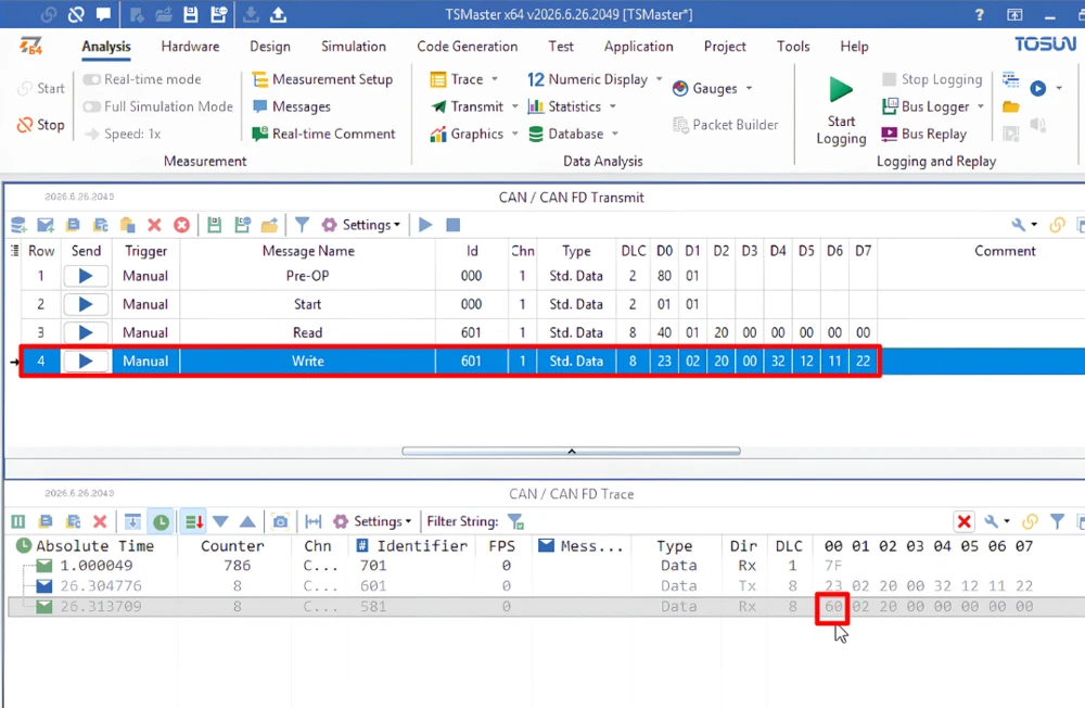
The response sent by the node contains the command byte 0x60, indicating that the write is successful. If we read back the data stored inside the object 0x2002:00, we should get the same data bytes that we wrote.
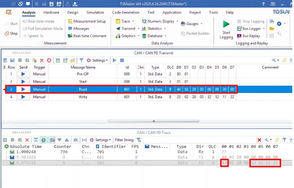
It’s worth knowing that the number of data bytes the master sends has to match the object exactly. A 32-bit object needs 4 data bytes. A 16-bit object needs 2. If the master tries to write only 2 data bytes into a 32-bit object, the node won’t accept it. It will respond with an SDO abort (0x80) instead, since the data size doesn’t match what the object expects.
Conclusion
We looked at how SDO communication works in CANopen, and how it’s used to read and write objects inside a node’s object dictionary. We went through the read command format, the response format, and understood how the command byte encodes the number of data bytes being sent. We also went through the write command format, and saw how the node responds with either a success or an abort.
On the hardware side, we tested reads on the Vendor ID and Producer Heartbeat Time objects, and tested writes on the 8-bit, 16-bit, and 32-bit objects in our application region.
Download STM32 CANopen SDO Protocol Project Files
The same CubeMX project from the earlier parts, tested on real hardware with SDO read and write commands. Free to download — support the work if it helped you.
Browse More STM32 CANopen Tutorials

Subscribe
Login
0 Comments
Newest

