Updated On: April 16, 2026
STM32 TCP/IP with Mongoose: Complete Setup Guide
STM32 microcontrollers like the F7 and H7 series come with a built-in Ethernet MAC, which means you do not need an external network controller to get wired communication working. This simplifies the hardware side quite a bit.
On the software side, we will use Mongoose Networking Library to handle the networking stack. It is a lightweight library that supports TCP/IP, HTTP, WebSocket, MQTT, and more. Compared to LWIP, it is easier to set up and integrates cleanly into a bare-metal STM32 project.
In this tutorial, we will go through the full setup from CubeMX configuration to running a simple web server that controls an onboard LED from a browser. The project files are available for download at the end of this article.
This tutorial is Part 1 of the STM32 TCP/IP with Mongoose series. You can explore the other tutorials below:
- STM32 HTTP Webserver using Mongoose
- STM32 Weather Station using Mongoose
- STM32 OTA Firmware Update using Mongoose

Table Of Contents
- STM32 Ethernet Architecture: MAC, PHY, and Mongoose Explained
- CubeMX Setup for STM32 Mongoose: Clock, Ethernet, UART, and LED
- How to Add Mongoose to an STM32 Project (mongoose_config.h)
- STM32 HTTP Web Server with Mongoose: LED Control via Browser
- STM32 Ethernet with Mongoose — Complete Setup Tutorial Video
- Download STM32 TCP/IP with Mongoose Project Files
- STM32 Mongoose TCP/IP — Frequently Asked Questions
STM32 Ethernet Architecture: MAC, PHY, and Mongoose Explained
The MAC and PHY
Ethernet communication involves two main components: the MAC (Media Access Controller) and the PHY (Physical Layer transceiver).
The MAC handles the data side, things like framing, addressing, and error detection. The PHY handles the physical side, converting digital signals into the electrical signals that travel over the cable.
STM32 microcontrollers like the H7 and F7 series have a built-in MAC, but they do not include a PHY. So you will need an external PHY chip on your board. Most STM32 development boards like the STM32H745 Discovery come with one already soldered on.
The MAC and PHY communicate with each other over either an MII or RMII interface. RMII is the more common choice since it uses fewer pins.
What is Mongoose?
Mongoose is a lightweight networking library built for embedded and IoT applications. It has its own built-in TCP/IP stack and supports HTTP, WebSocket, MQTT, and more. Mongoose also supports TLS/SSL through mbedTLS or OpenSSL if you need secure communication. It runs on STM32, ESP32, and several other platforms, so it is fairly portable as well.
The key advantage is simplicity. You add two files to your project, configure a header file, and the networking stack is ready to use.
Below are some important features of the Mongoose:
- Embedded Web Server: Serve web pages and REST APIs directly from your device.
- Built-in Protocols: Supports HTTP, WebSocket, MQTT, and more.
- TLS/SSL Support: Secure communication using mbedTLS or OpenSSL.
- Lightweight & Portable: Minimal footprint, runs on STM32, ESP32, and many platforms.
The Plan
We will follow the approach recommended in the Mongoose documentation. The implementation is broken down into three steps:
- Build a minimal skeleton firmware on the board
- Add Mongoose and get the TCP/IP stack working
- Add a web server or any other network feature you need
The first step is about making sure the basics are working, clock, UART, Ethernet pins, and LED, before touching any networking code.
CubeMX Setup for STM32 Mongoose: Clock, Ethernet, UART, and LED
What is a Skeleton Firmware?
Before integrating any library, it is a good practice to first get a minimal working firmware running on the board. This is called a skeleton firmware.
The idea is simple. Get the basics working first, the clock, UART, Ethernet pins, and an LED, and confirm that everything is functioning correctly before adding any networking code on top. This saves a lot of debugging time later.
For this tutorial, the skeleton firmware will do the following:
- Set CPU clock to the maximum frequency,
- Set up LED pins to GPIO output mode, and blink an LED,
- Set up network hardware, e.g. initialise Ethernet pins,
- Set up UART and prints debug log on a console
I am using a STM32H745 Discovery board for this project. Therefore, I will create a skeleton firmware for this board.
Once all of this is working, we move on to integrating Mongoose.
Clock Configuration
The image below shows the clock configuration used for this project.
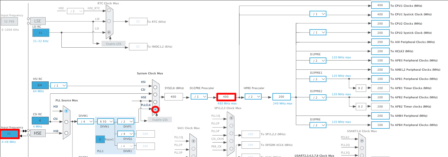
The board has a 25MHz external crystal and the system clock is running at 400MHz. Make sure your clock configuration matches your board before moving forward, as an incorrect clock setup can cause issues with Ethernet timing later.
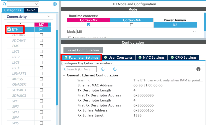
Ethernet Peripheral Configuration
The images below shows the Ethernet peripheral configuration in CubeMX.
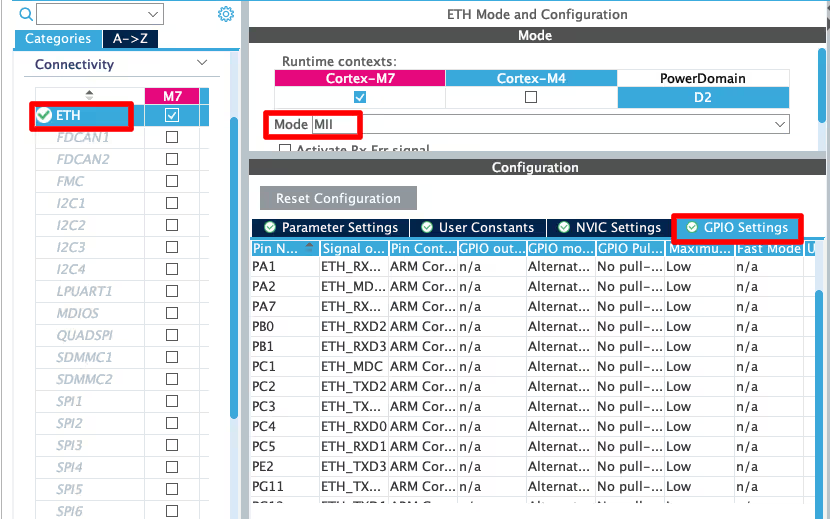
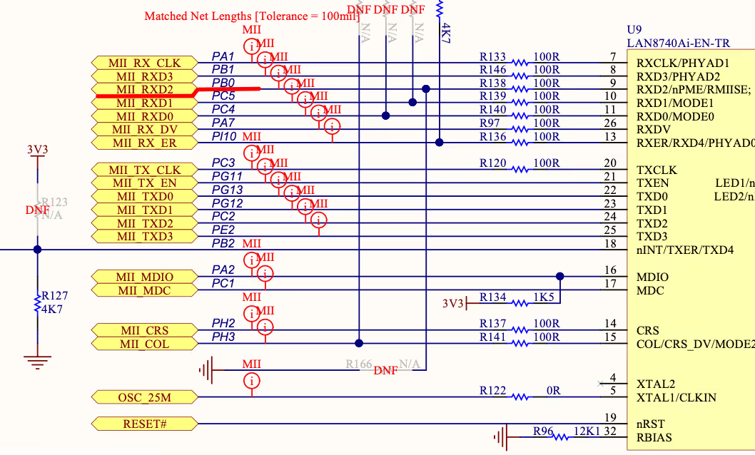
One thing to be careful about here is the pin mapping. The pins that CubeMX assigns by default are not always correct for every board. You should cross check the assigned pins against your board’s schematic before generating the code.
For the STM32H745 Discovery board, CubeMX assigned PH6 as ETH_RXD2, but according to the schematic, it should be PB2. So PB2 was manually configured as ETH_RXD2 instead.
The parameter configuration inside the Ethernet settings can be left at default.
UART Configuration
The image below shows the UART configuration. I am using USART3 for this project.
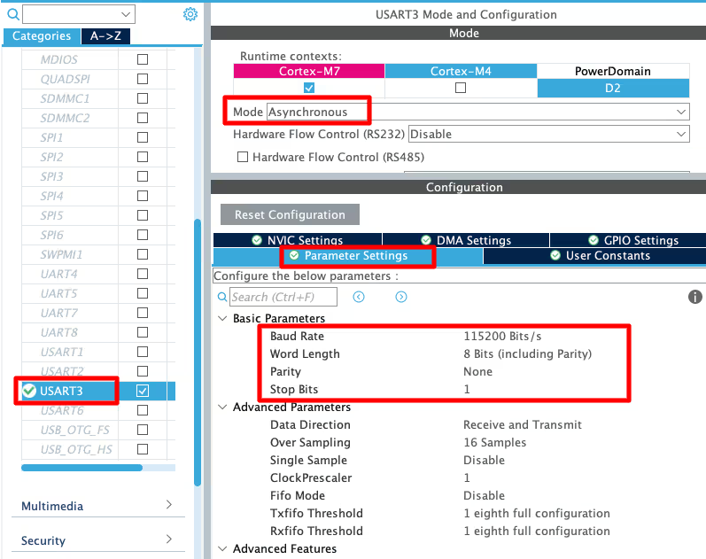
USART3 is configured in asynchronous mode with the following settings:
- Baud Rate: 115200
- Data Bits: 8
- Stop Bits: 1
- Parity: None
This will be used to print debug logs to the serial console, which is important for verifying the Ethernet connection later.
LED Pin Configuration
A GPIO pin needs to be configured as output for the LED. This will be used to verify the firmware is running and later to test the web server controls. The image below shows the LED pin configuration.
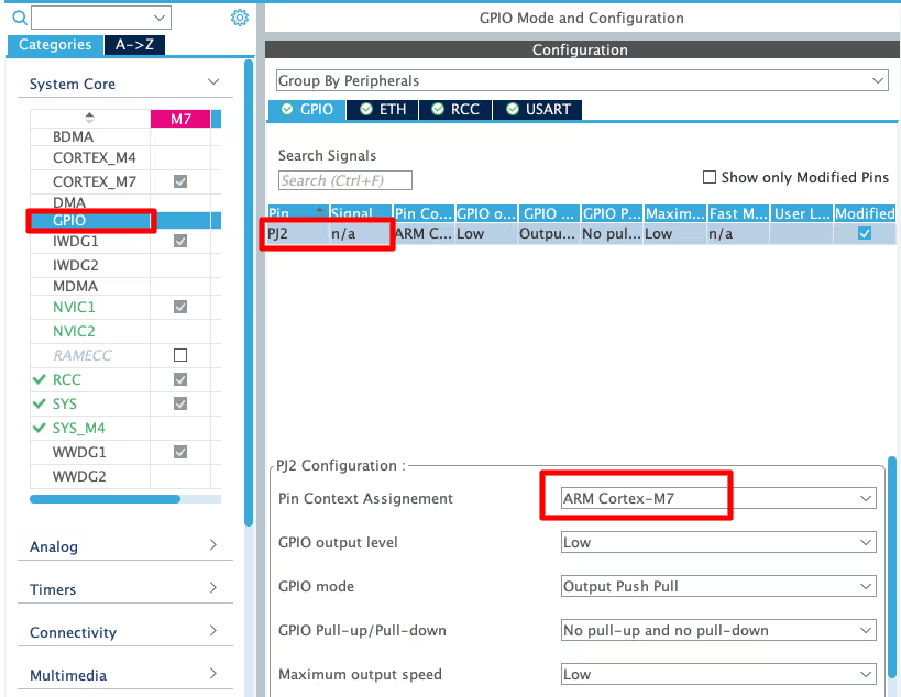
If you are working with a dual core STM32 like the H745, make sure to assign the LED pin to the correct core in the pin configuration. Assigning it to the wrong core means your code simply will not control it.
RNG Configuration
The image below shows the RNG configuration in CubeMX.
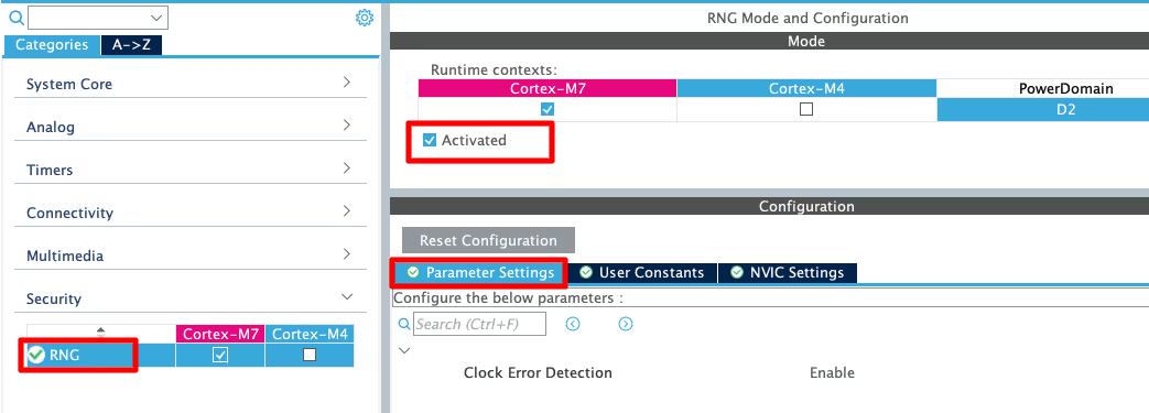
The Random Number Generator is enabled here so that Mongoose can use it to generate a random MAC address for the device. If your hardware does not have an RNG peripheral, you can skip this step. Mongoose has a software fallback for generating random numbers, so it will still work.
Writing and Testing the Skeleton Code
Now we will write a small piece of code to verify that everything configured so far is working correctly. This is just a basic test before we bring in Mongoose.
Above the main function, add the following code:
/* USER CODE BEGIN 0 */
int _write(int fd, unsigned char *buf, int len) {
  if (fd == 1 || fd == 2) {
    HAL_UART_Transmit(&huart3, buf, len, 999);
  }
  return len;
}

uint64_t mg_millis(void) {
  return HAL_GetTick();
}
/* USER CODE END 0 */The _write function redirects printf output to UART, so anything you print shows up on the serial console.
The mg_millis function returns the current tick count, which Mongoose will use internally for timing.
Inside the while loop in main, add this:
while (1) {
  printf("Tick: %lu\r\n", HAL_GetTick());
  HAL_Delay(500);
}This prints the uptime to the serial console every 500ms. If you can see this printing correctly, the clock and UART are both working fine.
The image below shows the expected output on the serial console.
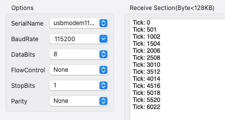
The uptime value should be incrementing every 500ms as shown. Once you see this, the skeleton firmware is ready and we can move on to integrating Mongoose.
How to Add Mongoose to an STM32 Project (mongoose_config.h)
Adding the Source Files
Mongoose is distributed as two files, mongoose.c and mongoose.h. There is no separate installation or package manager involved. You just add these files directly to your project.
Create a new source file mongoose.c and two header files mongoose.h and mongoose_config.h in your project. Then go to the Mongoose GitHub page and copy the contents of mongoose.c and mongoose.h into the respective files you just created. These two files do not need any modification.
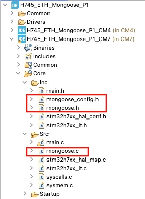
All the configuration is handled separately through mongoose_config.h, which we will set up next.
Configuring mongoose_config.h
Below is the content of the mongoose_config.h file:
#pragma once
#define MG_ARCH MG_ARCH_NEWLIB             // For all ARM GCC based environments
#define MG_ENABLE_TCPIP 1                  // Enables built-in TCP/IP stack
#define MG_ENABLE_CUSTOM_MILLIS 1          // We must implement mg_millis()
#define MG_ENABLE_TCPIP_PRINT_DEBUG_STATS 1  // Enable debug stats log
#define MG_ENABLE_CUSTOM_RANDOM 1
#define MG_TCPIP_PHY_ADDR 1

// Uncomment the driver for your device
#define MG_ENABLE_DRIVER_STM32H 1
// #define MG_ENABLE_DRIVER_STM32F 1Here is what each definition does:
MG_ARCH_NEWLIBtells Mongoose that we are using an ARM GCC based environment, which is the case for all STM32 projects in CubeIDE.MG_ENABLE_TCPIP 1enables the built-in TCP/IP stack. This is required.MG_ENABLE_CUSTOM_MILLIS 1tells Mongoose that we are providing our ownmg_millis()function. We already defined this in the skeleton firmware usingHAL_GetTick().MG_ENABLE_CUSTOM_RANDOM 1tells Mongoose that we are providing our own random number generator. We will define themg_randomfunction in the next section. If your board does not have a hardware RNG, set this to 0 and Mongoose will handle it internally using its own software implementation.MG_TCPIP_PHY_ADDR 1sets the PHY address. The default for STM32 boards is 0, but if your project does not work, try changing this value. It can range from 0 to 4 depending on the device.
For the driver, uncomment the line that matches your board. Since this project uses the STM32H745, MG_ENABLE_DRIVER_STM32H is uncommented. If you are on an STM32F series board, uncomment MG_ENABLE_DRIVER_STM32F instead.
Choosing Between DHCP and Static IP
By default, Mongoose uses DHCP to assign an IP address. If your board is connected to a router, you do not need to do anything extra. The IP address will be assigned automatically and you can read it from the UART logs once the board connects.
If you are connecting the Ethernet cable directly to your computer, DHCP will not work since there is no router to assign an address. In that case, you need to define a static IP in mongoose_config.h:
#define MG_TCPIP_IP   MG_IPV4(192, 168, 0, 10)   // IP
#define MG_TCPIP_GW   MG_IPV4(192, 168, 0, 1)    // Gateway
#define MG_TCPIP_MASK MG_IPV4(255, 255, 255, 0) // NetmaskUse an IP address that is in the same subnet as your computer’s Ethernet adapter. We will cover how to configure the computer side in a later section.
Writing the Initialization Code
Now we will add the Mongoose initialization code to the main file.
First, define the mg_random function above the main function. This function uses the hardware RNG we configured in CubeMX to generate a random MAC address for the device:
/* USER CODE BEGIN 0 */
bool mg_random(void *buf, size_t len) {
  for (size_t n = 0; n < len; n += sizeof(uint32_t)) {
    uint32_t r;
    HAL_RNG_GenerateRandomNumber(&hrng, &r);
    memcpy((char *) buf + n, &r, n + sizeof(r) > len ? len - n : sizeof(r));
  }
  return true;
}
/* USER CODE END 0 */Next, create a run_mongoose function. This function initializes the Mongoose event manager and runs an infinite polling loop that handles all network events:
static void run_mongoose(void) {
  struct mg_mgr mgr;        // Mongoose event manager
  mg_mgr_init(&mgr);        // Initialise event manager
  mg_log_set(MG_LL_DEBUG);  // Set log level to debug
  for (;;) {
    mg_mgr_poll(&mgr, 0);   // Process network events
  }
}This function has its own infinite loop, so it should be called after all initializations are complete, right before the while loop in main:
int main() {
  ....
  /* USER CODE BEGIN 2 */
  run_mongoose();
  /* USER CODE END 2 */
  while (1) {}
}
Note:
Since run_mongoose never returns, the while loop in main will never be reached. If you are using an RTOS, run this function in a separate task with at least 8KB of stack space.
Configuring Your Computer’s Ethernet (Direct Connection)
This section only applies if you are connecting the Ethernet cable directly from the STM32 board to your computer. If you are using a router, skip this.
You need to manually set your computer’s Ethernet adapter to be in the same subnet as the static IP you defined earlier.
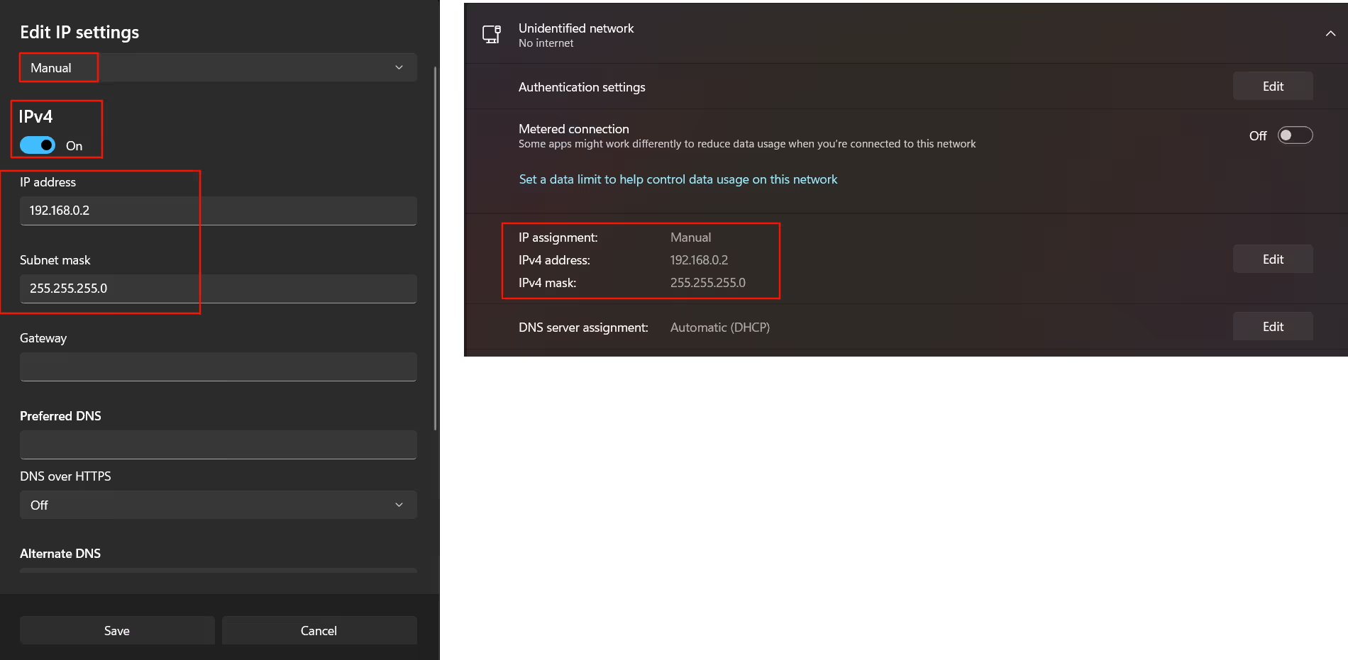
On Windows:
The image below shows the IPv4 settings for a Windows computer.
On Mac:
The image below shows the network settings on a Mac.
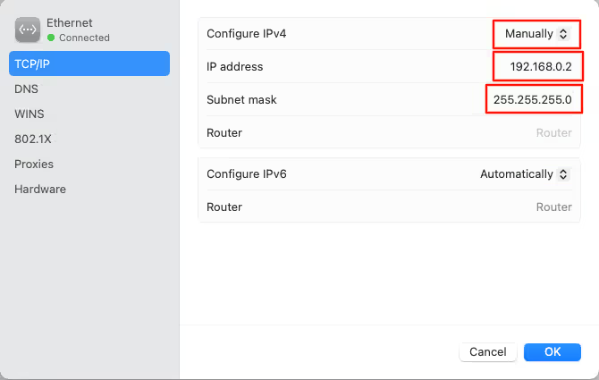
Set the IP to something in the same subnet, for example 192.168.0.2, with a subnet mask of 255.255.255.0. The gateway can be set to 192.168.0.1.
Verifying the Output: Reading the Serial Logs
Flash the project to the board and open your serial console. You should see output similar to the image below.
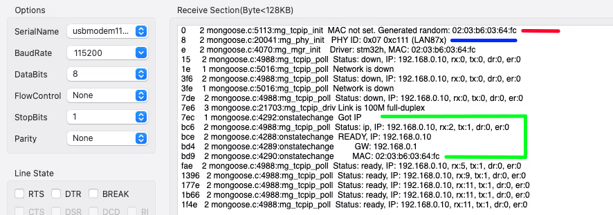
Here is what the log lines mean:
- The Red Line shows that a random mac is generated at the beginning. If the logs are stuck at this line itself, it means either the Ethernet pins are not configured correctly, or the PHY address is wrong.
- The Blue Line shows that the PHY is initialised.
- The Green box shows that the link is now UP and running with the IP address 192.168.0.10.
If you are using DHCP, you will see something like as shown below.
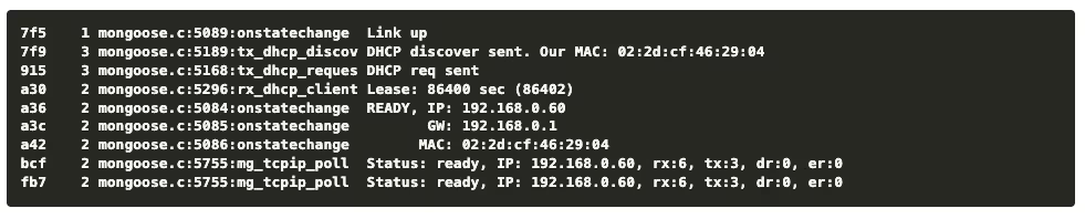
Once you see the link up message with a valid IP, the Mongoose TCP/IP stack is working. You can confirm it further by running a ping test from your computer:
ping 192.168.0.10The image below shows a successful ping response from the board.
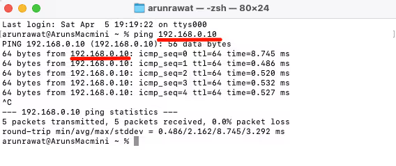
If the board is responding to pings, the Ethernet driver is working correctly and we are ready to move on to setting up the web server.
STM32 HTTP Web Server with Mongoose: LED Control via Browser
Now that the Ethernet is working, we can go a step further and set up a simple web server on the board. We will create an HTTP server that serves a web page and allows you to control an onboard LED from the browser.
Adding the HTTP Listener
Inside the run_mongoose function, add the following line before the infinite loop:
mg_http_listen(&mgr, "http://0.0.0.0:80", event_handler, NULL);This sets up an HTTP listener on port 80 that listens on all available network interfaces. Whenever an HTTP request comes in, it will be passed to the event_handler function, which we will define next.
Writing the Event Handler
Add the following function before run_mongoose:
static void event_handler(struct mg_connection *c, int ev, void *ev_data) {
  if (ev == MG_EV_HTTP_MSG) {
    struct mg_http_message *hm = (struct mg_http_message *) ev_data;

    if (mg_match(hm->uri, mg_str("/api/led/get"), NULL)) {
      mg_http_reply(c, 200, "", "%d\n", HAL_GPIO_ReadPin(GPIOJ, GPIO_PIN_2));
    }
    else if (mg_match(hm->uri, mg_str("/api/led/toggle"), NULL)) {
      HAL_GPIO_TogglePin(GPIOJ, GPIO_PIN_2);
      mg_http_reply(c, 200, "", "true\n");
    }
    else {
      struct mg_http_serve_opts opts = {.root_dir = "/web_root", .fs = &mg_fs_packed};
      mg_http_serve_dir(c, hm, &opts);
    }
  }
}This function handles incoming HTTP requests. Here is what each part does:
/api/led/getreads the current state of the LED and sends it back as a response./api/led/toggletoggles the LED and confirms the action with a response.- Any other request is served from the packed filesystem, which contains the web page files.
Make sure to replace GPIOJ and GPIO_PIN_2 with the actual GPIO port and pin you configured for the LED on your board.
Enabling the Packed Filesystem
The web page files need to be embedded into the firmware. Mongoose handles this through a packed filesystem. Add the following two lines to your mongoose_config.h:
#define MG_ENABLE_PACKED_FS 1  // Enable packed filesystem
#define MG_ENABLE_POSIX_FS 0 // Disable POSIX filesystemMG_ENABLE_PACKED_FS 1 enables the packed filesystem so Mongoose can serve files embedded in the firmware. MG_ENABLE_POSIX_FS 0 disables the POSIX filesystem since we are on bare metal and do not have a standard file system available.
Getting the Web UI
Mongoose provides a ready-made web UI that you can use directly. Visit the following link: https://mongoose.ws/ui-pack
This page generates a packed_fs.c file that contains the web page embedded as a C array. Download it and add it to your project. No modifications are needed.
Once added, rebuild and re-flash the project to the board.
Testing the Web Server
Open a browser on your computer and go to the IP address of your board. If you are using the static IP from earlier, that would be: http://192.168.0.10
You should see a web page with an LED control button as shown in the GIF below. the LED on the board will respond to the button on the web page.

As you can see, clicking the button on the web page toggles the LED on the board. With this, the basic web server setup is complete.
STM32 Ethernet with Mongoose — Complete Setup Tutorial Video
Watch the complete walkthrough of this tutorial — CubeMX configuration for Ethernet, UART, LED and RNG, setting up the Mongoose library, configuring the TCP/IP stack, and testing the web server that controls an onboard LED from a browser.
Download STM32 TCP/IP with Mongoose Project Files
Complete CubeMX project for the STM32H745 Discovery board, including Mongoose configuration, skeleton firmware, and HTTP web server with LED control. Free to download — support the work if it helped you.
STM32 Mongoose TCP/IP — Frequently Asked Questions
Conclusion
In this tutorial, we started by building a skeleton firmware on the STM32H745 Discovery board, getting the clock, UART, Ethernet pins, and LED all working before touching any networking code. From there, we integrated the Mongoose library by adding the source files, configuring mongoose_config.h, and writing the initialization code to get the TCP/IP stack running. By the end, we had a working web server serving a page from the browser and controlling an onboard LED over HTTP.
The setup we have here is a solid foundation for any STM32 project that needs network connectivity. Whether you want to build a monitoring dashboard, expose a REST API, or control peripherals remotely, this is the base you will build on top of. Mongoose keeps things straightforward and the whole thing runs on bare metal without needing an RTOS or a heavy middleware stack.
In the next part, we will use the Mongoose Device Dashboard to generate a project and set up a proper HTTP web server with a clean UI. This will take things further from the basic LED toggle we did here and give you a more complete starting point for real applications.
Browse More STM32 Mongoose TCP/IP Tutorials

STM32 Weather Station Web Server using Mongoose (Ethernet + BME280)

STM32 OTA Firmware Update using Mongoose – Step by Step Guide

STM32 Real-Time Graph using Mongoose Ethernet

STM32 Fixed Memory Pool for Networking using Mongoose and O1heap
STM32 Mongoose with W5500 – Ethernet on Any STM32 MCU
STM32 Modbus TCP Server – Read Input Registers with Mongoose

STM32 Modbus TCP Server – Read Discrete Inputs with Mongoose

Subscribe
Login
0 Comments
Newest
