Home ▸ STM32 Tutorials ▸ ADC Series ▸
Updated On: April 16, 2026
STM32 ADC Injected Conversion Mode – Triggered and Auto Injection
The STM32 ADC regular conversion mode works through a fixed sequence — it samples channels in order and there is no way to interrupt it mid-sequence. But in real-time applications like motor control or fault detection, some signals are time-critical and need to be sampled immediately, even if a regular conversion is already in progress. This is exactly what injected conversion mode is designed for.
In this tutorial, we will explore how injected ADC channels work, how they differ from regular channels, and when to use each of the two available injection modes — triggered injection and auto injection. We will configure both modes in CubeMX, write the HAL code to handle regular and injected conversions simultaneously, and verify the timing of both groups using a logic analyzer on the STM32H750.
This is the 8th tutorial in the STM32 ADC series. You can go through the other parts of this series, here are the links:
- STM32 ADC Conversion Time & Frequency Explained
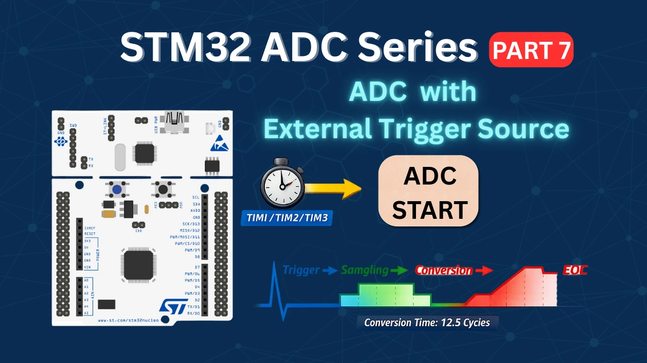
- ADC External Trigger Source Selection
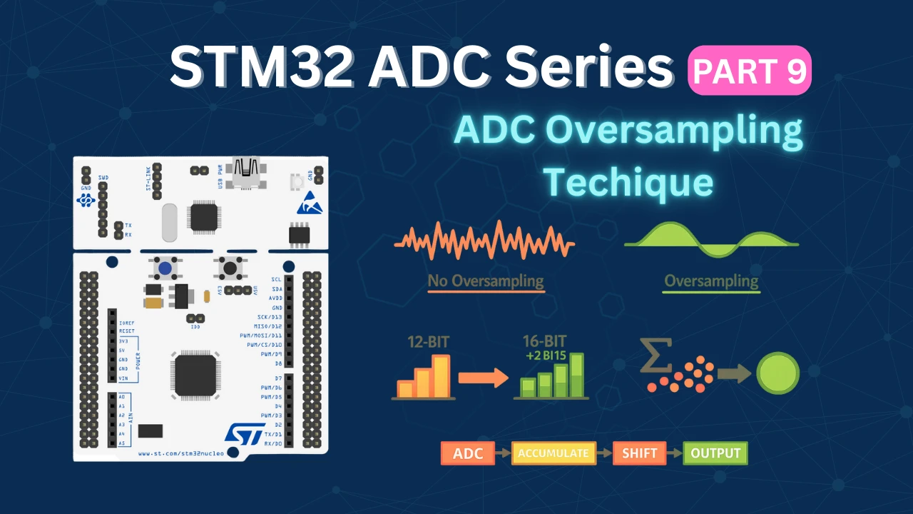
- STM32 ADC Hardware Oversampling
- ADC Reference Voltage Explained
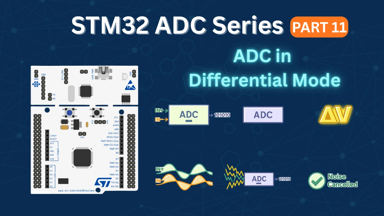
- ADC in Differential Mode
Table Of Contents
- STM32 ADC Injected Conversion Mode: How It Works and When to Use It
- STM32 ADC Injected Mode: CubeMX Setup for Regular and Injected Channels
- Potentiometers to STM32 ADC: Wiring Diagram (6-Channel Setup)
- STM32 HAL Code for ADC Injected Conversion: Callbacks & Data Registers
- STM32 ADC Injected Mode Output: Triggered vs Auto Injection Timing
- STM32 ADC Injected Conversion Mode — Video Tutorial
- Download STM32 ADC Injected Conversion Project Files
- STM32 ADC Injected Conversion Mode — Frequently Asked Questions
STM32 ADC Injected Conversion Mode: How It Works and When to Use It
An “injected conversion” is a high-priority analog-to-digital converter (ADC) conversion that can interrupt a regular conversion sequence when triggered by an external event or software command, allowing for immediate measurement of a specific channel even while other conversions are ongoing. Essentially, it “injects” a new conversion into the ongoing process.
Advantages over the Regular Conversion:
The Injected Conversion have following Advantages over the Regular Conversion:
- The Injected channels has higher priority. Therefore an injected group can interrupt the ongoing Regular Conversion (Triggered Mode only).
- Injected conversion have separate data registers for each converting channel. Therefore we can read them in sequence, and still get the results for all the converting channels. Whereas for regular group there is only one data register for all the converting channels, and hence we need to use the DMA to read multiple channels.
There are two available modes of injected conversion:
- triggered injection mode
- auto-injection mode
Triggered Injection Mode
In triggered mode, the conversion starts either by an external trigger source or by the software itself.
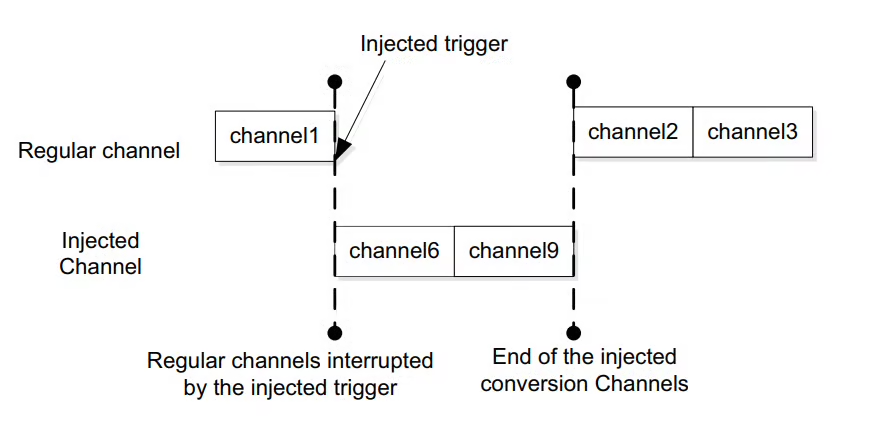
If an external injected conversion starts during the conversion of a regular group of channels, the current regular conversion is reset, and the injected channel sequence switches are launched. This means that all injected channels are converted once. Then, the regular conversion of the regular group of channels is resumed from the last interrupted regular conversion.
Basically the Injected channels have higher priority than the regular channels.
Auto Injection Mode
In Auto Injection mode, the injected group is converted at the end of the regular group. In most of the STM32 devices we have up to 16 channels in the regular group and up to 4 channels in the injected group. Therefore we can have a total of 20 channels together.
If the continuous Conversion Mode is enabled, the injected channels can be converted continuously along with the regular channels.
Why Do We Need ADC Injected Conversion?
In many real-time embedded applications, some analog signals are more important than others and must be sampled immediately. The regular ADC conversion mode works in a fixed sequence and cannot always respond instantly when a critical measurement is required. The Injected Conversion mode solves this problem by allowing high-priority ADC channels to be converted on demand, even if the ADC is already busy with regular conversions.
Injected conversions can be triggered by software or hardware events and are designed to interrupt the regular ADC sequence. Once the injected conversion is completed, the ADC automatically resumes the regular conversions from where it left off. This makes injected mode ideal for applications such as fault detection, current sensing in motor control, or any scenario where certain signals must be captured with minimal latency.
The table below highlights the differences between Regular conversion and Injected Conversion Modes.
| Feature | Regular Conversion | Injected Conversion |
|---|---|---|
| Priority | Normal priority | High priority |
| Execution | Follows a fixed sequence | Can interrupt regular sequence |
| Trigger Source | Software or external trigger | Software or external trigger |
| Timing Control | Sequential, less flexible | Immediate, event-driven |
| Data Registers | Regular ADC data register | Separate injected data registers |
| Typical Use Case | Continuous sensor sampling | Time-critical or event-based measurements |
STM32 ADC Injected Mode: CubeMX Setup for Regular and Injected Channels
The cubeMX configuration will remain the same across different STM32 MCUs I tested, therefore I am not writing separate configuration for other devices. Although the Timer configuration can vary depending on the clock configuration of the MCU. You can check the previous tutorial for different Timer configuration as the external trigger source.
Regular Conversions
Below is the image showing the ADC configuration for multiple channels in regular conversion mode.
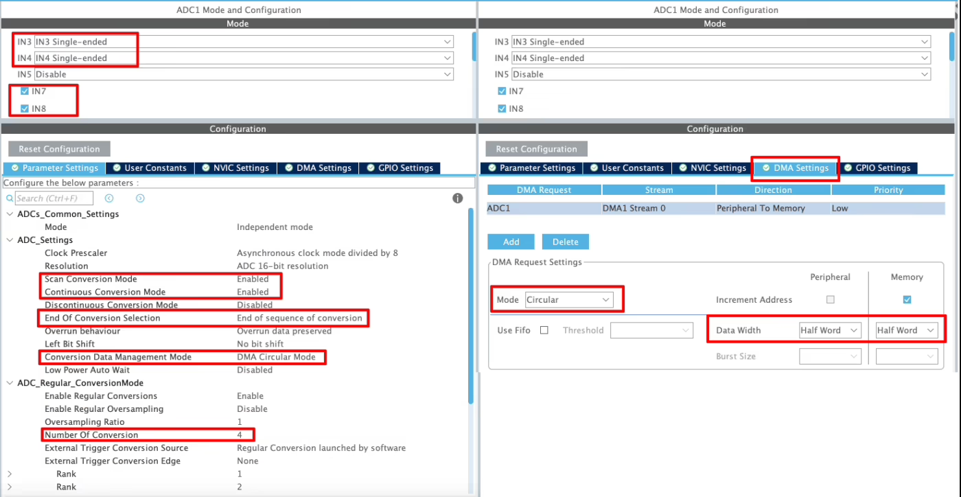
I have enabled 4 channels of the ADC1. This is where the 4 potentiometers will be connected to.
Since we are using 4 different Channels of ADC1, set the Number of Conversions (under ADC_Regular_ConversionMode) to 4. This will automatically enable the Scan Conversion Mode, which is necessary in case of Multiple Channels.
You can configure the Rank and Sampling Time for each channel. The Rank determines the sequence in which the channels will be converted.
The Continuous Conversion Mode should be Enabled. Doing so will make sure the ADC start another conversion for all the channels automatically. This way the ADC will keep converting the data continuously.
The Conversion Data Management Mode should be set to DMA Circular. This is to make sure that the DMA does requests the data continuously from the ADC. This mode should be used while using the DMA in Circular mode.
The End of Conversion Selection should be set at the end of sequence of conversion. Doing this will make sure that the Conversion complete interrupt in only triggered when all the 4 channels (one complete sequence) have been converted.
In the DMA section, add the DMA request for the ADC1. Also make sure that the DMA is configured in the Circular Mode. In this mode the DMA will transfer the data continuously. I have configured the ADC resolution of 16bits, therefore the data width is set to Half-Word (16bits).
Triggered Injection Mode
Below is the image showing the configuration for the Injected channels in the triggered mode.
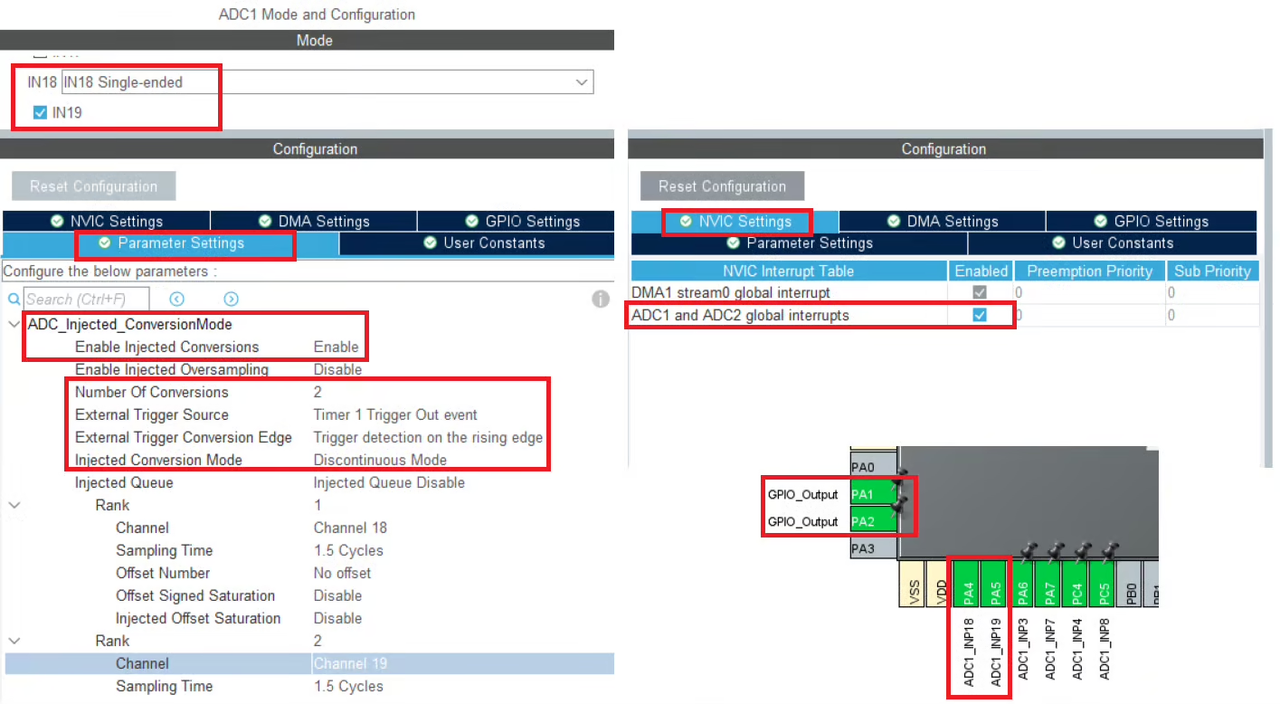
- I have enabled the 2 channels in the injected Conversion Mode, channel 18 and channel 19.
- Since we are using the triggered injection mode, the trigger source is set to Timer 1 trigger out event. We can also use the software mode here, but in that case we need to manually start the ADC.
- The Injected Conversion Mode is set to Discontinuous mode.
- The ranks are configured for both channels, and I have set the minimum sampling time for each.
- We will use the injected channels in the interrupt mode, therefore we need to enable the ADC interrupt in the NVIC tab.
- We have a total of 6 channels now. 2 for the injected conversions and 4 for the regular conversions.
Timer Configuration
We are using Timer1’s event to trigger the ADC conversion. Before we configure the timer, we must find more details about where this timer is connected to. Below is the image showing some details about it.
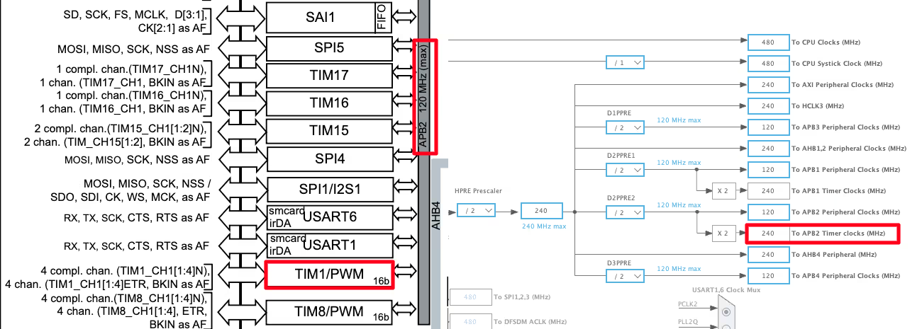
The First half of the image above is taken from the H750 Datasheet. It shows that the TIM1 is connected to the APB2 Bus. The Second Half of the image is showing the clock configuration for this project. The APB2 Timer clock is running at 240MHz clock, so this will be the TIM1 clock as well.
We will now configure the TIM1’s Prescaler and ARR to reduce this clock to the desired ADC sampling rate we need.
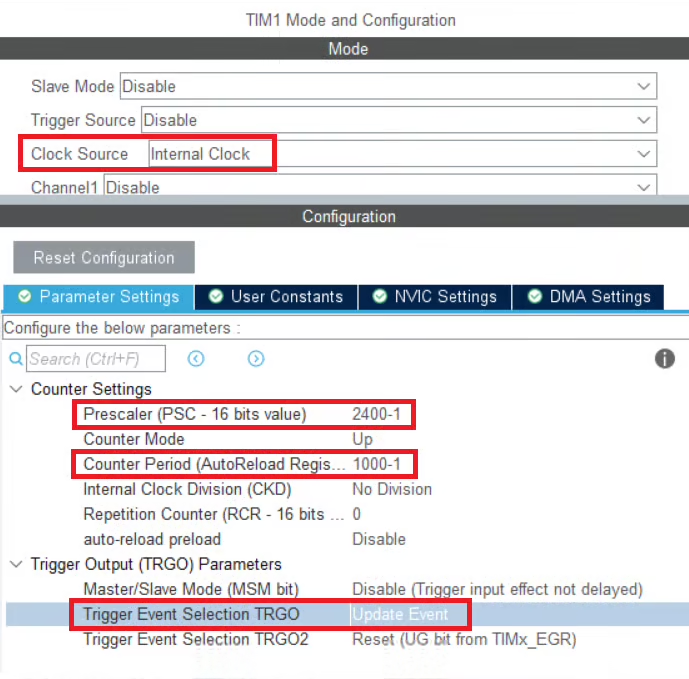
We will first enable the internal clock as the clock source for TIM1, which is running at a frequency of 240 MHz. To generate a periodic trigger for the ADC, we configure the timer prescaler and auto-reload register (ARR) as shown below.
Step 1: Prescaler Configuration
The prescaler divides the timer clock according to:
After applying the prescaler, TIM1 counts at 100 kHz.
Step 2: Auto-Reload Register (ARR) Configuration
The ARR defines how many timer counts occur before an update event (overflow) is generated:
This corresponds to an update event every:
Step 3: Trigger Event Selection
In CubeMX, select Update Event as the trigger source. This configures the ADC to start a conversion every time the TIM1 counter overflows.
How It Works
- TIM1 counter starts counting up from 0.
- When the counter reaches the ARR value, it overflows.
- The overflow generates an update event.
- This update event is used as the external trigger for the ADC conversion.
This configuration ensures precise, hardware-timed ADC triggering every 10 ms, which is ideal for injected or regular ADC conversions requiring deterministic timing.
Auto Injection Mode
Below is the image showing the configuration for the Injected channels in the Auto Injection mode.
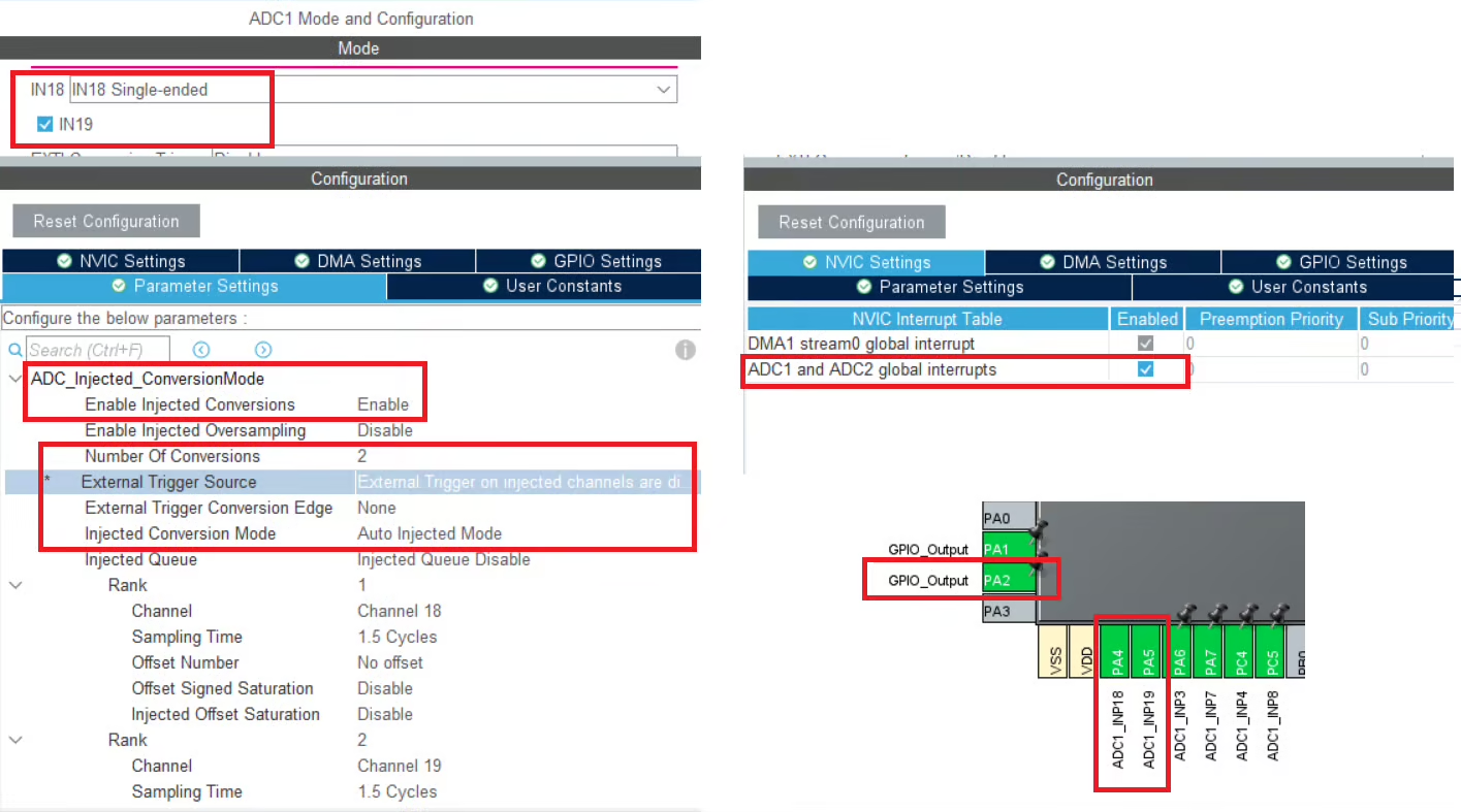
This configuration is largely the same as the one used for Triggered Injection mode, with one key difference: the Injected Conversion mode is set to Auto Injection Mode. In Auto Injection mode, the injected channels are automatically converted at the end of the regular conversion sequence, without requiring any external or software trigger.
Because the injected conversions are internally chained to the regular group, all injected trigger sources are disabled. This mode is useful when injected channels must always be sampled immediately after the regular conversions, ensuring a fixed and predictable conversion order without relying on additional timing or trigger signals.
Cortex M7 Related Configuration
In this section we will cover the configuration and code exclusively needed for the cortex M7 devices.
We know that as per ST’s recommendation, we should use the Instruction and Data cache to improve the system performance. But if the cache are enabled, the DMA will always have the cache coherency issue. This is why we will use the Memory Processing Unit (MPU) of the cortex M7 to deal with the cache coherency.
Below is the image showing the MPU configuration in the cortex M7 Devices.
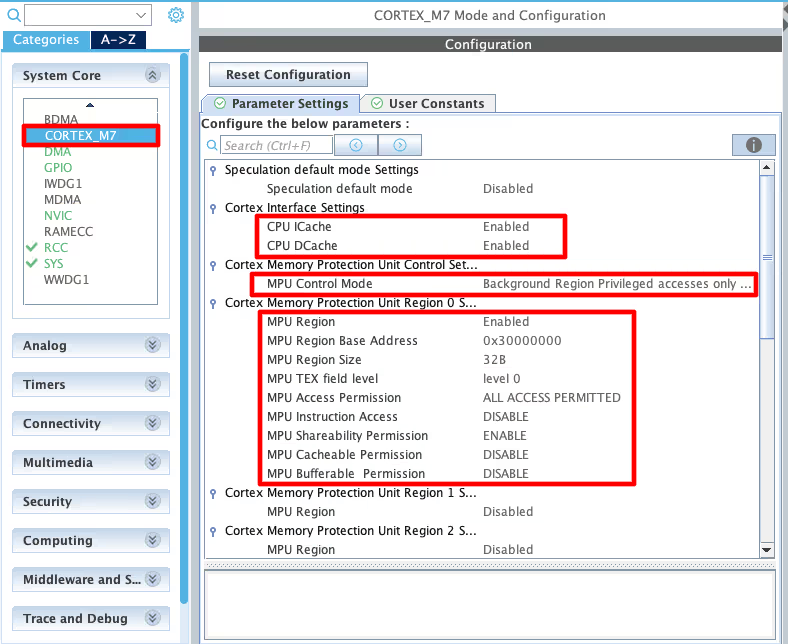
As you can see in the image above, I have enabled both Instruction and Data Cache (ICache & DCache).
We also need to enable the MPU in the MPU_PRIVILEGED_DEFAULT mode. Here I am choosing the Base Address region 0x30000000, this is the region for the RAM_D2 and we will relocate our buffer in this region.
- Here I have selected the 32 Bytes region, since it’s the least size available. The ADC Buffer is going to be 20 bytes in size.
- The rest of the configuration is to set the region as non-cacheable region. This would prevent the cache coherency issue between the CPU and the DMA.
In the main file, we need to relocate the ADC_VAL array to the RAM_D2 Region, 0x30000000. We can do this by using the section attribute as shown below.
__attribute__((section(".adcarray"))) uint16_t ADC_VAL[4];Here I am relocating the ADC_VAL array to the section “.adcarray“. The section (.adcarray) will be defined in the flash script file as shown below.
  .mysection (NOLOAD):
  {
    . = ABSOLUTE(0x30000000);
    *(.adcarray)
} >RAM_D2As you can see above, the section (.adcarray) is linked to the region RAM_D2 (0x30000000).
The rest of the code remains the same as we used in the DMA section.
Potentiometers to STM32 ADC: Wiring Diagram (6-Channel Setup)
Below is the image showing the connection between the potentiometers and the H750.
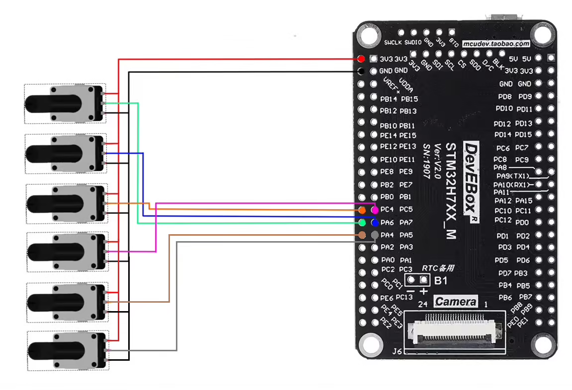
As shown in the image above, six potentiometers are connected to six analog input pins of the MCU. These pins are configured as ADC channels, where four channels belong to the Regular conversion group and the remaining two channels are assigned to the Injected conversion group.
Each potentiometer is powered from the MCU’s 3.3 V supply, allowing the ADC to measure a variable analog voltage between 0 V and 3.3 V based on the potentiometer position. This setup makes it easy to observe and compare the behavior of regular and injected ADC conversions in real time.
STM32 HAL Code for ADC Injected Conversion: Callbacks & Data Registers
The code will remain the same for all the STM32 MCUs. If there are any changes, I will specify in this section itself.
Definitions
Let’s define some variables, which we will use in the main function later.
//uint16_t ADC_VAL[4];
__attribute__((section(".adcarray"))) uint16_t ADC_VAL[4];  // cortex M7 only
uint16_t ADC_INJ_VAL[2];ADC_VAL is an array of 4 elements of 16 bit in size. We will use this array to store the Regular channels converted Values. Even if you are using 10bits, 12bits or 14bits resolution the ADC_VAL will still be defined as a 16 bit variable.
ADC_INJ_VAL is an array of 2 elements of 16 bit in size. We will use this array to store the Injected channels converted Values. We will use the injected conversion in the interrupt mode, hence this array does not need the relocation like the ADC_VAL.
The main function
Below is the main function.
int main()
{
  ....
  HAL_TIM_Base_Start(&htim1);
  HAL_ADC_Start_DMA(&hadc1, ADC_VAL, 4);
  HAL_ADCEx_InjectedStart_IT(&hadc1);
  while (1)
  {
  }
}Inside the main function we will first start the TIM1 in the base mode. This will start will Timer’s counter, which will start counting up. Once the counter overflows, an event will trigger, which will start the ADC Injected conversions. The counter than resets back to 0 and starts counting UP again.
Next we will start the ADC in DMA Mode. The parameter ADC_VAL is the array where we want to store the converted data, and 4 is the number of conversions we want the DMA to transfer.
Finally we will start the Injected channels in the interrupt mode.
Once the ADC regular group finishes all the conversions, an interrupt will trigger and the ADC Conversion Callback will be called.
void HAL_ADC_ConvCpltCallback(ADC_HandleTypeDef *hadc)
{
  HAL_GPIO_TogglePin(GPIOA, GPIO_PIN_1);
}Inside this callback we will toggle the pin PA1. This pin toggles each time the callback is called and hence it can be used to calculate the time interval of the callback function. We will measure it on the scope.
Similarly when the injected conversion is finished, another interrupt will trigger and the ADC injected Conversion complete callback will be called.
void HAL_ADCEx_InjectedConvCpltCallback(ADC_HandleTypeDef *hadc)
{
	HAL_GPIO_WritePin(GPIOA, GPIO_PIN_2, GPIO_PIN_SET);
	ADC_INJ_VAL[0] = HAL_ADCEx_InjectedGetValue(hadc, ADC_INJECTED_RANK_1);
	ADC_INJ_VAL[1] = HAL_ADCEx_InjectedGetValue(hadc, ADC_INJECTED_RANK_2);
	HAL_GPIO_WritePin(GPIOA, GPIO_PIN_2, GPIO_PIN_RESET);
}Inside this callback we will first set the pin PA2, then read the converted values from the injected group and finally reset the pin PA2.
As I mentioned earlier, the injected group have separate registers to store the data for individual channels. Therefore we can read the values for the respective ranks inside the same callback.
STM32 ADC Injected Mode Output: Triggered vs Auto Injection Timing
We will see the results for both, triggered injection mode and auto injection mode.
Triggered Injection Mode
Below is the image showing the ADC data on the live expression.
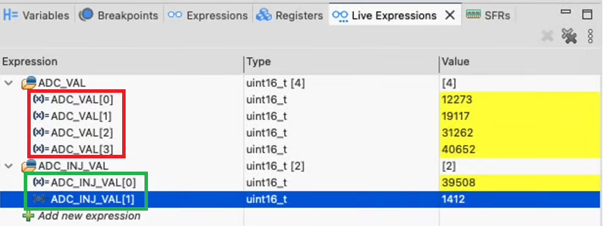
As you can see in the image above we are getting the readings for all 6 channels, 4 channels of the regular group and 2 channels in Injected Mode.
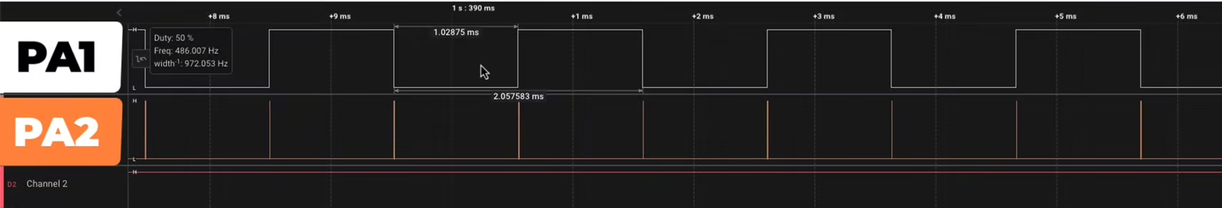
We will see the pin triggers on the logic analyzer. Below is the image showing the triggers for pin PA1 and PA2.
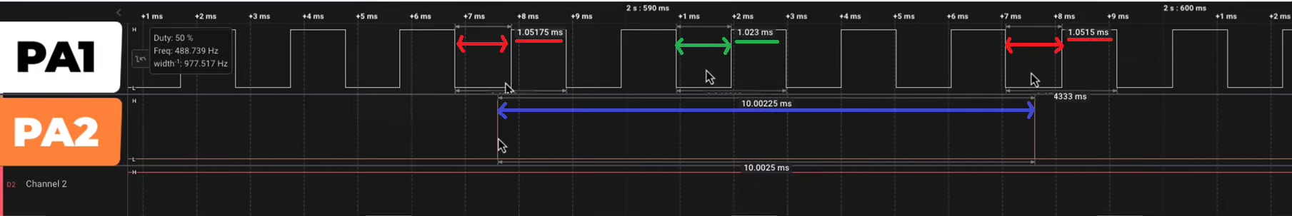
The pin PA1 toggles whenever the ADC finished the conversion and the DMA finished the transfer for all the regular channels. Whereas the pin PA2 toggles whenever the conversion for the injected channels is finished.
The pin PA1 toggles every 1.02ms (Indicated by Red Colour) while the pin PA2 toggles every 10ms (Indicated by Blue Colour). We have configured the TIM1 to trigger an event every 10ms, therefore the injected channels are converted every 10ms.
Note that whenever PA2 toggles, the HIGH/LOW time for PA1 increases to 1.05ms (Indicated by Green Colour). This is because the injected channels interrupt the ongoing regular group conversion, which is resumed when the injected conversion is finished.
This proves that the Injected group can interrupt the regular group. Also since we are getting the data for both the injected channels, this means that the data for injected channels is stored in separate registers, which we can read individually.
Auto Injection Mode
Below is the image showing the ADC data on the live expression.
As you can see in the image above we are getting the readings for all 6 channels, 4 channels of the regular group and 2 channels in Injected Mode.
We will see the pin triggers on the logic analyzer. Below is the image showing the triggers for pin PA1 and PA2.
The pin PA1 toggles whenever the ADC finished the conversion and the DMA finished the transfer for all the regular channels. Whereas the pin PA2 toggles whenever the conversion for the injected channels is finished.
As you can see in the image above, the pin PA2 toggle at the end of the PA1’s toggle. This means that the injected channels are converted at the end of the regular channels. This is exactly what the auto injection mode is used for.
STM32 ADC Injected Conversion Mode — Video Tutorial
Watch the complete walkthrough of this tutorial — understanding triggered and auto injection modes, configuring regular and injected channels in CubeMX, writing the HAL code to read both channel groups, and verifying conversion timing and interrupt behaviour on a logic analyzer.
Download STM32 ADC Injected Conversion Project Files
Complete CubeMX project for the STM32H750, covering both triggered and auto injection modes alongside regular DMA circular conversion, including HAL code and logic analyzer verification. Free to download — support the work if it helped you.
STM32 ADC Injected Conversion Mode — Frequently Asked Questions
Conclusion
In this tutorial, we explored STM32 ADC injected conversion mode in both its triggered and auto injection forms. We covered what injected channels are, how they differ from regular channels in terms of priority and dedicated data registers, and when each mode is the right tool for the job. Through CubeMX configuration, HAL code, and logic analyzer measurements, we confirmed that triggered injection interrupts the regular sequence and resumes it afterwards, while auto injection chains cleanly to the end of the regular group.
Injected mode is especially valuable in applications where certain measurements simply cannot wait — fault detection, current sensing synchronized with a PWM cycle, or any scenario where a high-priority signal needs to be captured without discarding an ongoing regular conversion. The dedicated data registers mean you can read all injected channel results independently without DMA, which simplifies the code significantly compared to handling multiple regular channels.
In the next tutorial, we will look at ADC hardware oversampling, a technique that allows STM32 to improve effective ADC resolution and reduce noise by accumulating multiple samples internally — without any extra CPU or DMA involvement. If you found this tutorial useful, stay tuned for that one.
Browse More STM32 ADC Tutorials
STM32 ADC Multiple Channels with Circular DMA: CubeMX Setup & HAL Code
STM32 ADC Multiple Channels Without DMA: CubeMX Setup & HAL Code
STM32 ADC Conversion Time: Formula, Calculation & Frequency Explained
STM32 ADC External Trigger with Timer: CubeMX & HAL Guide
STM32 ADC Hardware Oversampling: Improve Resolution & Reduce Noise
STM32 ADC Reference Voltage: VREFINT, VREF+ & VREFBUF
STM32 ADC Differential Mode: Setup, CMV, and HAL Code Guide

Subscribe
Login
0 Comments
Newest
