Updated On: February 22, 2026
How to Receive UART Data in Blocking & Interrupt mode
In this tutorial, we will explore how to receive UART data on STM32 using both blocking and interrupt modes. You will learn how blocking mode works, why it can limit your program’s responsiveness, and how using interrupts allows the CPU to handle other tasks while receiving data in the background. We will also cover how to handle fixed-length and variable-length data efficiently, and how to implement reliable UART reception in your STM32 projects using HAL.
This is the 3rd tutorial in the series on the UART peripheral of STM32 Microcontrollers. In this series we will cover different ways of transmitting and receiving data over the UART protocol. We will also see different UART modes available in the STM32 microcontrollers and how to use them.
In this tutorial, we will see how to receive the data using the blocking mode and in the interrupt mode and what are the advantages and disadvantages for the both. We will also see how to receive the data of unknown length.
How UART Receiving Works on STM32
UART allows the STM32 to collect data sent from an external device (like a PC, sensor, or another microcontroller). The STM32 can handle this in many ways: blocking mode, interrupt mode and DMA Mode. In this tutorial, we will see the blocking mode and interrupt mode.
Blocking Mode Reception
- In blocking mode, the CPU waits for a set number of bytes to arrive using
HAL_UART_Receive(). - The CPU is stalled until the transfer completes or a timeout occurs.
- This method is simple to implement but has serious limitations for real-time applications:
- Other tasks (LEDs, sensors) are paused.
- You must know exactly how many bytes will arrive.
- Data can be missed if it arrives outside of the receive call.
Interrupt Mode Reception
- Interrupt-based reception (
HAL_UART_Receive_IT()) allows the CPU to perform other tasks while UART collects data. - When a byte or a set of bytes arrives, an interrupt triggers and
HAL_UART_RxCpltCallback()handles the data. - Benefits over blocking mode:
- CPU is free between interrupts.
- Works well for real-time systems.
- Can handle variable-length data with proper buffer management.
The table below summarises the differences between the Blocking and Interrupt modes.
| Feature | Blocking Mode | Interrupt Mode |
|---|---|---|
| CPU Usage | High – CPU waits | Low – CPU free between interrupts |
| Real-Time Performance | Poor – other tasks delayed | Excellent – other tasks run concurrently |
| Data Length Requirement | Must know in advance | Can handle fixed or variable length |
| Implementation Complexity | Simple | Moderate – requires callbacks |
| Best Use | Small, predictable messages | Background reception, real-time applications |
STM32 UART Hardware Setup
We will use the STM32 MCU to send the data to the computer. Some of the Nucleo and Discovery dev boards from ST supports the virtual com port. This feature enables the USB connected for the ST-link to be also used for the data transmission between the MCU and the computer.
The Virtual Com Port is supported by many Nucleo and Discovery boards but not all. You need to check the schematic of the board to confirm whether the respective board supports it.
Below are the images from the schematic of the Nucleo F446RE and Discovery F412.
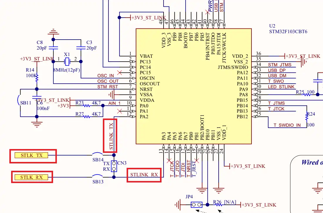
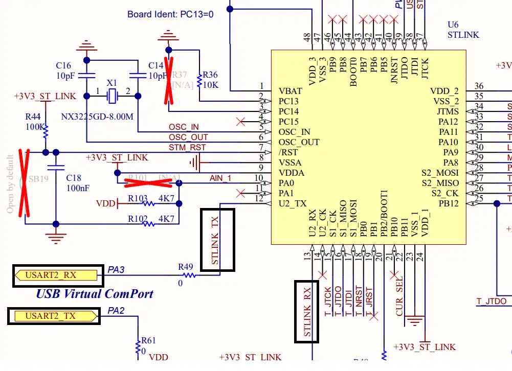
As you can see in the images above, both Nucleo F446RE and Discovery F412 supports the USB Virtual Com Port. So if you are using either of these boards, you do not need to use an additional module to communicate to the computer. The USB used for the ST link can also be used for the communication.
Not all the boards support this Virtual Com port feature. Below is the image from the schematic of the very famous STM32F4 Discovery board.
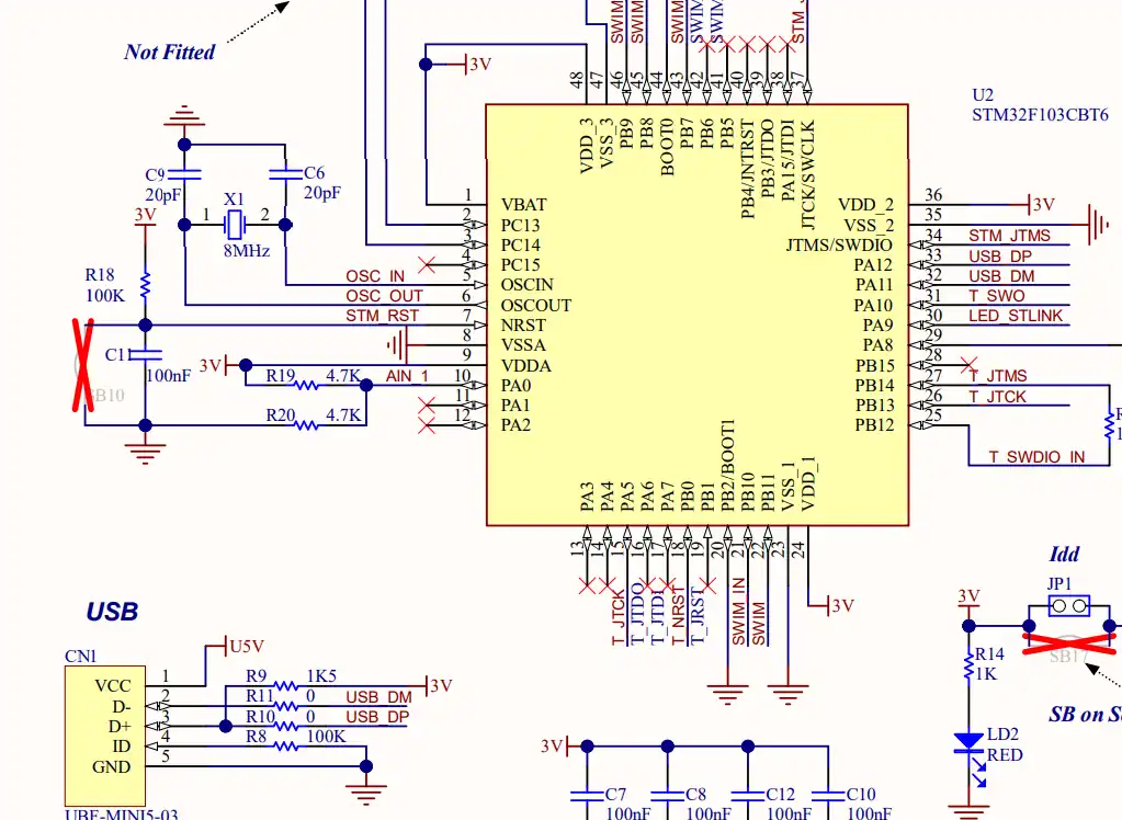
As you can see in the image above, there is no virtual com port in the F4 Discovery board. In such cases we can use some module to convert the UART signals to the USB, which is connected to the computer.
The image below shows the connection between the MCU and the FT232 USB to UART converter.
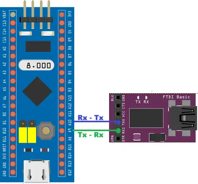
The UART is always connected in the cross connection, connecting the TX pin of the MCU to the RX of the device and the RX to the TX of the device. The module then connects to the computer using the USB.
Receive UART Data in Blocking Mode
In Blocking mode, the CPU is blocked and it waits for the required number of bytes to arrive or the timeout, whatever happens first. This prevents the CPU from running other tasks until all the required data have arrived or the timeout happened.
STM32 CubeMX UART Configuration
The image below shows the UART configuration in CubeMX.
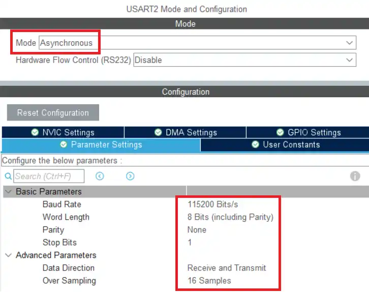
We will use the Asynchronous Mode for the communication. Only 2 pins are used in the Asynchronous mode, TX and RX. The baud rate is set to 115200. We need to use the same baud rate for the receiver device also.
HAL Code to Receive UART data in Blocking Mode
Below is the code showing how to receive 5 bytes in the blocking mode.
  while (1)
  {

	  HAL_UART_Receive(&huart2, RxData, 5, 1000);

	  HAL_GPIO_TogglePin(GPIOA, GPIO_PIN_5);
	  HAL_Delay(1000);
}The function HAL_UART_Receive is used to received the 5 bytes of data in the blocking mode. The timeout is set to 1 second.
If the 5 bytes are received before 1 second, the function will exit and the LED will blink. If there is no data incoming, the CPU will still be blocked for 1 second. This will affect the LED blinking rate and the it will blink every 2 seconds.
Also if the CPU is waiting for the delay (HAL_Delay(1000)) and the data arrived in that period, the data will be simply lost.
So a lot of things needs to go right in order to receive the data in the blocking mode. The data must arrive when the control is inside the receive function. We also need to know the data size in advance, so that we can program the MCU to receive number of bytes.
Receive UART Data in Interrupt Mode
The interrupt mode helps us receive the data in the background. The CPU can process other tasks as usual and once the required number of bytes has been received, the interrupt will trigger.
STM32 CubeMX UART Configuration
Below is the cubeMX configuration for the interrupt.
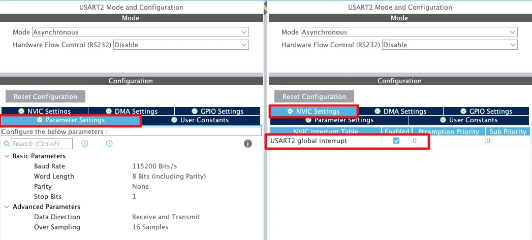
The main UART configuration remains the same as used in the blocking mode. The only change we need to make here is enable the UART interrupt in the NVIC tab.
HAL Code to Receive UART data in Interrupt Mode
Below is the code showing how to receive 5 bytes of data in the interrupt mode.
int main ()
{
  ......
  HAL_UART_Receive_IT(&huart2, RxData, 5);
  while (1)
  {
	  HAL_GPIO_TogglePin(GPIOA, GPIO_PIN_5);
	  HAL_Delay(1000);
  }
}HAL_UART_Receive_IT is used to receive 5 bytes of data in the interrupt mode. The data will be received in the background and the CPU will continue to blink the LED every 1 second.
Once all the 5 bytes have been received, an interrupt will trigger and the RX complete callback will be called. We can process the data inside the callback function.
void HAL_UART_RxCpltCallback(UART_HandleTypeDef *huart)
{
	// do something with the data

	HAL_UART_Receive_IT(&huart2, RxData, 5);
}In the code above, I am not performing any operation with the data. The interrupt is disabled after each trigger, so we need to call the function HAL_UART_Receive_IT again at the end of the callback.
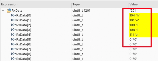
Below is the image showing the data received in the RxData buffer. Also the LED is blinking every 1 second indicating that the rest of the processes work as usual.
Receive Data of unknown length
The interrupt method shown above can receive the data in the background but we still need to provide how many data bytes we are expecting. We can modify the code above to receive the data of unknown length.
Basically we will receive 1 byte at a time and store it in a buffer. There will be a terminating character in the data which will indicate that all the data has been transmitted. Once we have received this character, we will process the received data. Below is the code shows the implementation.
uint8_t FinalData[20];
uint8_t RxData[20];
uint8_t temp[2];
int indx = 0;

void HAL_UART_RxCpltCallback(UART_HandleTypeDef *huart)
{
	memcpy(RxData+indx, temp, 1);
	if (++indx >= 20) indx = 0;
	HAL_UART_Receive_IT(&huart2, temp, 1);
}

int main()
{
  ....
  HAL_UART_Receive_IT(&huart2, temp, 1);
  while (1)
  {

	if (temp[0] == '\n')
	{
        	memcpy (FinalData, RxData, indx);
		indx = 0;
	}

	HAL_GPIO_TogglePin(GPIOA, GPIO_PIN_5);
	HAL_Delay(1000);
}The HAL_UART_Receive_IT is set to receive only 1 byte. The interrupt will trigger after receiving each data byte and hence the callback will be called.
Inside the callback we will store the data received in the RxData buffer. The index variable keeps track of how many bytes have been received and it also helps in storing the new data at a new position in the buffer.
We will also monitor the the incoming byte for the terminating character (‘\n‘). Once we received the terminating character, this means that the sender has finished sending the data, so we can start processing it. Here I am just copying the data to the main buffer.
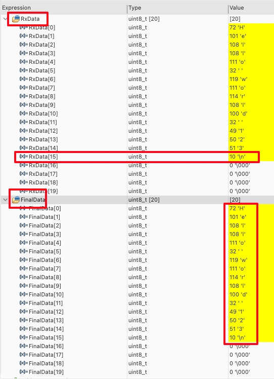
This method works well for receiving data of any length. Below is the image showing the data received in the RxData and main data buffer.
Although the method works well for small amount of data, but this could fail when you are receiving large data at a very high rate. The interrupt is being called for each byte and it do take a considerable amount of time to serve the ISR and call the callback. There is a chance that we might loose some data during that time.
You can check out the STM32 UART receive using Idle Line to receive data of unknown length without any restrictions.
Video Tutorial
STM32 UART Receive: Blocking & Interrupt
Step-by-step video showing how to receive UART data on STM32 using **blocking and interrupt modes**, so you can handle incoming bytes efficiently without missing data.
Watch the VideoConclusion
In this tutorial, we explored how to receive UART data on STM32 using blocking and interrupt modes. Blocking mode is simple to implement but pauses the CPU while waiting for data, making it unsuitable for real-time applications. Interrupt mode overcomes this limitation by allowing the CPU to perform other tasks while incoming bytes are handled in the background, ensuring that data is captured efficiently without missing any bytes.
Understanding the differences between blocking and interrupt reception helps you choose the right approach for your project. For small, predictable messages, blocking mode may be sufficient, but for responsive systems and real-time applications, interrupt-based reception is the preferred choice. Implementing these techniques in your STM32 projects ensures reliable UART communication and smoother multitasking for all your peripherals.
Browse More STM32 UART Tutorials
STM32 UART Part 2 – Transmit using DMA & Interrupt
STM32 UART DMA Receive: Normal & Circular Mode (HAL)
STM32 UART Idle Line: Receive Data via Interrupt & DMA
STM32 UART Part 6 – Half-Duplex Communication (Single-Wire Mode)
STM32 UART Part 7 – How to use one-Wire Protocol
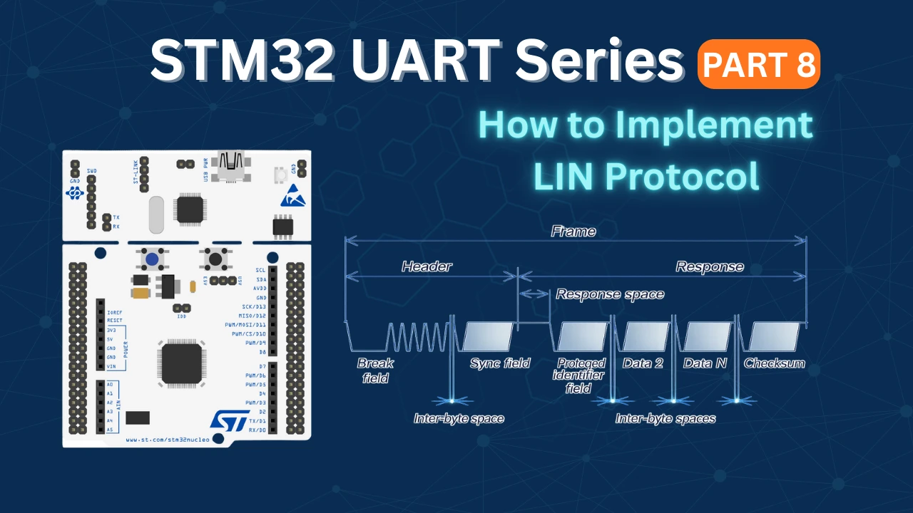
STM32 UART Part 8 – LIN Communication Tutorial
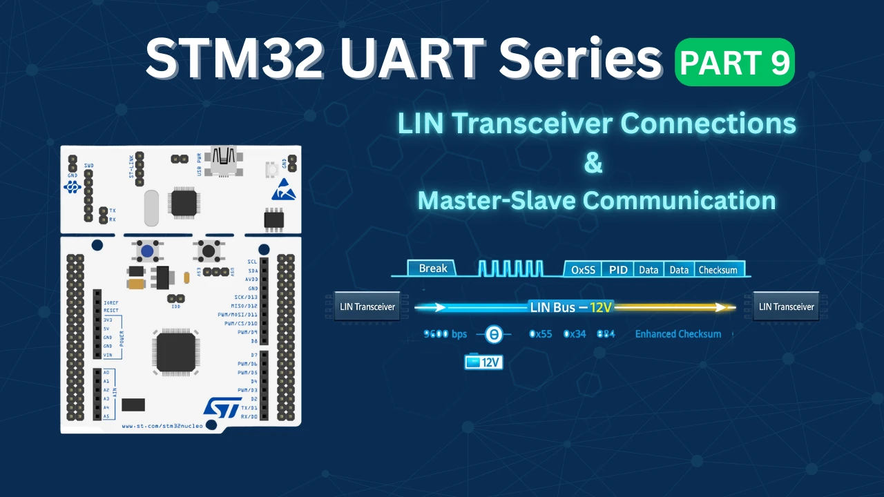
STM32 UART Part 9 – LIN Transceiver Connections & Master-Slave Communication
STM32 UART Receive Project Download
STM32 UART Receive FAQs

Subscribe
Login
0 Comments
Newest
